AUDI A4 1998 B5 / 1.G APB Engine Ignition System Checking
Manufacturer: AUDI, Model Year: 1998,
Model line: A4,
Model: AUDI A4 1998 B5 / 1.G
Pages: 64, PDF Size: 0.37 MB
AUDI A4 1998 B5 / 1.G APB Engine Ignition System Checking
A4 1998 B5 / 1.G
AUDI
AUDI
https://www.carmanualsonline.info/img/6/1052/w960_1052-0.png
AUDI A4 1998 B5 / 1.G APB Engine Ignition System Checking
Trending: immobilizer, sensor, oil change, light, belt, battery location, wiring diagram
Page 31 of 64
28-28
If display field 3 does not display a realistic
value:
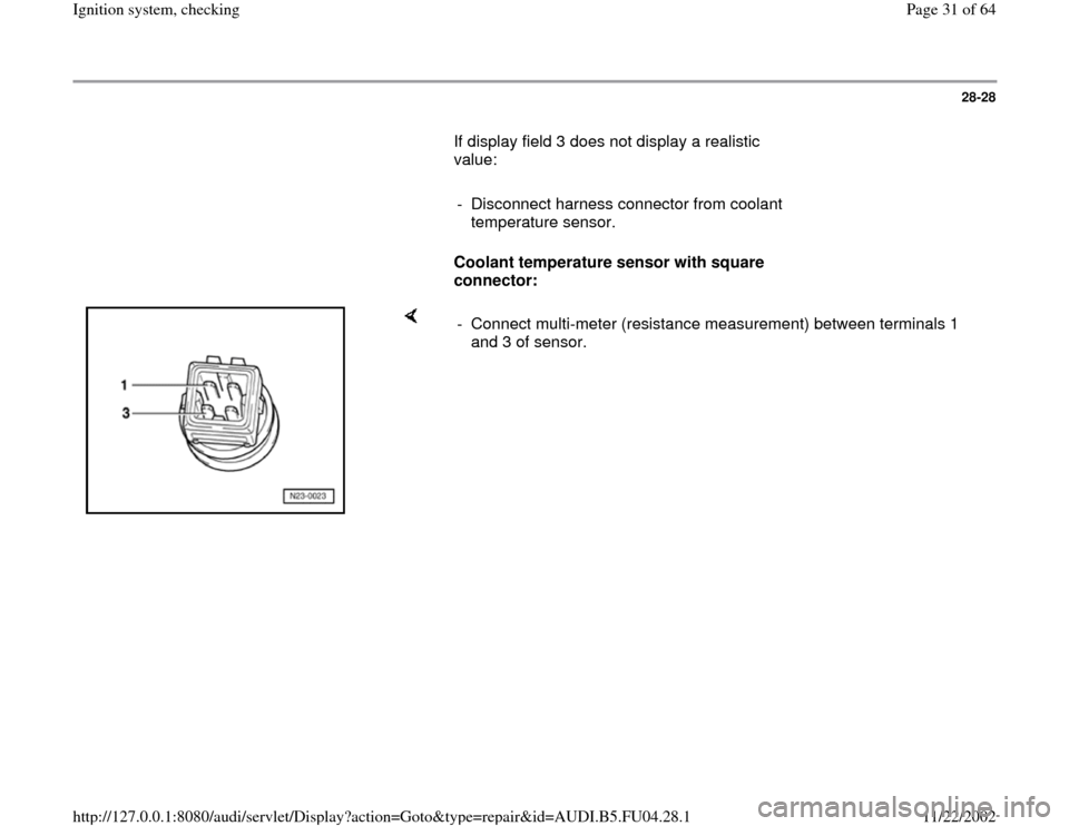
- Disconnect harness connector from coolant
temperature sensor.
Coolant temperature sensor with square
connector:
- Connect multi-meter (resistance measurement) between terminals 1
and 3 of sensor.
Pa
ge 31 of 64 I
gnition s
ystem, checkin
g
11/22/2002 htt
p://127.0.0.1:8080/audi/servlet/Dis
play?action=Goto&t
yp
e=re
pair&id=AUDI.B5.FU04.28.1
Page 32 of 64
28-29
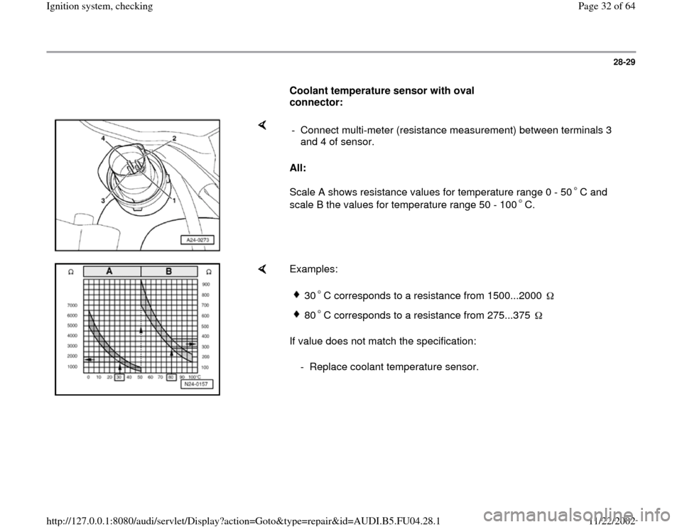
Coolant temperature sensor with oval
connector:
All:
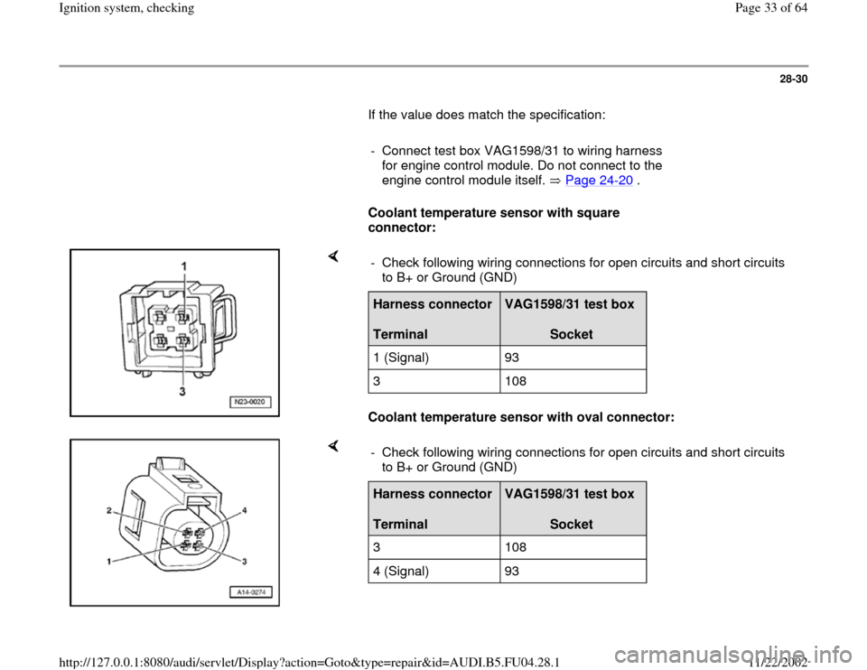
Scale A shows resistance values for temperature range 0 - 50 C and
scale B the values for temperature range 50 - 100 C. - Connect multi-meter (resistance measurement) between terminals 3
and 4 of sensor.
Examples:
If value does not match the specification:
30 C corresponds to a resistance from 1500...2000 80 C corresponds to a resistance from 275...375
- Replace coolant temperature sensor.
Pa
ge 32 of 64 I
gnition s
ystem, checkin
g
11/22/2002 htt
p://127.0.0.1:8080/audi/servlet/Dis
play?action=Goto&t
yp
e=re
pair&id=AUDI.B5.FU04.28.1
Page 33 of 64
28-30
If the value does match the specification:
- Connect test box VAG1598/31 to wiring harness
for engine control module. Do not connect to the
engine control module itself. Page 24
-20
.
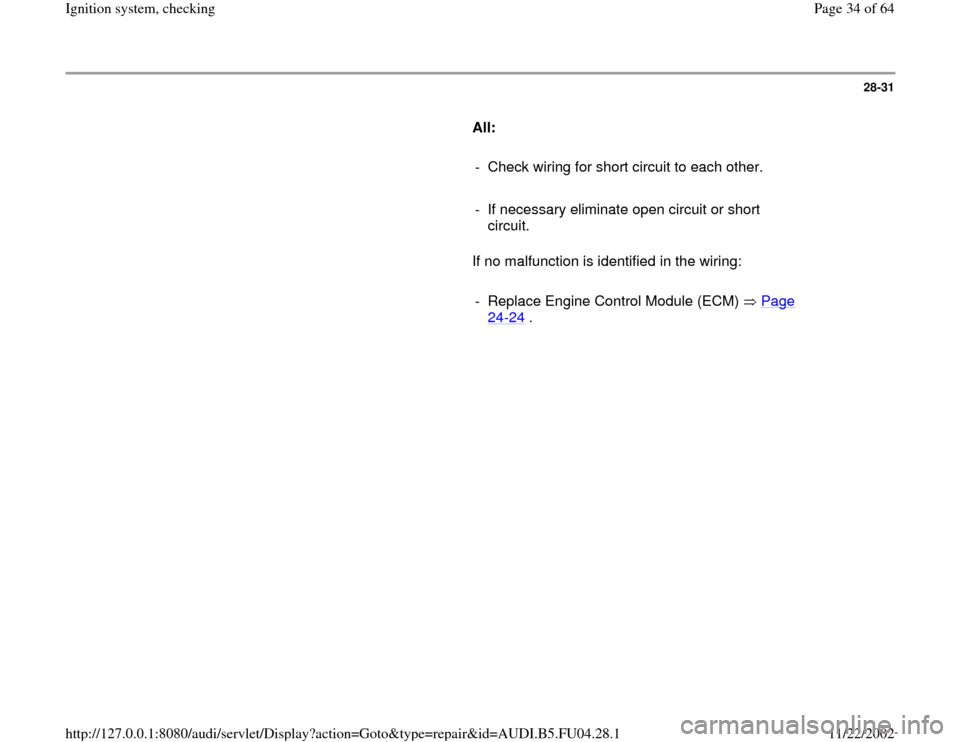
Coolant temperature sensor with square
connector:
Coolant temperature sensor with oval connector: - Check following wiring connections for open circuits and short circuits
to B+ or Ground (GND) Harness connector
Terminal
VAG1598/31 test box
Socket
1 (Signal) 93
3 108
- Check following wiring connections for open circuits and short circuits
to B+ or Ground (GND) Harness connector
Terminal
VAG1598/31 test box
Socket
3 108
4 (Signal) 93
Pa
ge 33 of 64 I
gnition s
ystem, checkin
g
11/22/2002 htt
p://127.0.0.1:8080/audi/servlet/Dis
play?action=Goto&t
yp
e=re
pair&id=AUDI.B5.FU04.28.1
Page 34 of 64
28-31
All:
- Check wiring for short circuit to each other.
- If necessary eliminate open circuit or short
circuit.
If no malfunction is identified in the wiring:
- Replace Engine Control Module (ECM) Page
24
-24
.
Pa
ge 34 of 64 I
gnition s
ystem, checkin
g
11/22/2002 htt
p://127.0.0.1:8080/audi/servlet/Dis
play?action=Goto&t
yp
e=re
pair&id=AUDI.B5.FU04.28.1
Page 35 of 64
28-32
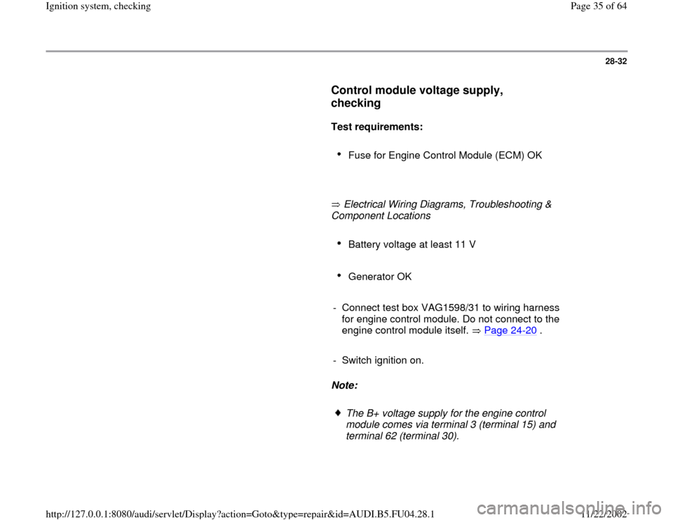
Control module voltage supply,
checking
Test requirements:
Fuse for Engine Control Module (ECM) OK
Electrical Wiring Diagrams, Troubleshooting &
Component Locations
Battery voltage at least 11 V
Generator OK
- Connect test box VAG1598/31 to wiring harness
for engine control module. Do not connect to the
engine control module itself. Page 24
-20
.
- Switch ignition on.
Note:
The B+ voltage supply for the engine control
module comes via terminal 3 (terminal 15) and
terminal 62 (terminal 30).
Pa
ge 35 of 64 I
gnition s
ystem, checkin
g
11/22/2002 htt
p://127.0.0.1:8080/audi/servlet/Dis
play?action=Goto&t
yp
e=re
pair&id=AUDI.B5.FU04.28.1
Page 36 of 64
The Ground (GND) connection for the engine
control module is via terminals 1 and 2.
Pa
ge 36 of 64 I
gnition s
ystem, checkin
g
11/22/2002 htt
p://127.0.0.1:8080/audi/servlet/Dis
play?action=Goto&t
yp
e=re
pair&id=AUDI.B5.FU04.28.1
Page 37 of 64
28-33
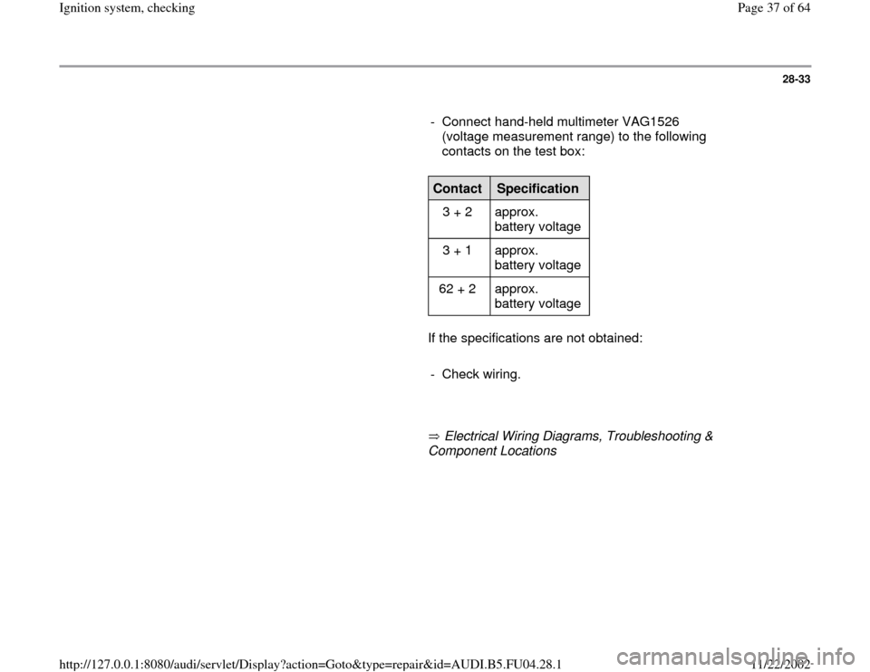
- Connect hand-held multimeter VAG1526
(voltage measurement range) to the following
contacts on the test box:
Contact
Specification
3 + 2 approx.
battery voltage
3 + 1 approx.
battery voltage
62 + 2 approx.
battery voltage
If the specifications are not obtained:
- Check wiring.
Electrical Wiring Diagrams, Troubleshooting &
Component Locations
Pa
ge 37 of 64 I
gnition s
ystem, checkin
g
11/22/2002 htt
p://127.0.0.1:8080/audi/servlet/Dis
play?action=Goto&t
yp
e=re
pair&id=AUDI.B5.FU04.28.1
Page 38 of 64
28-34
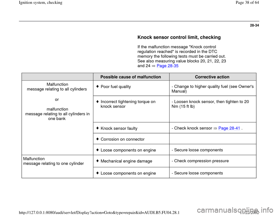
Knock sensor control limit, checking
If the malfunction message "Knock control
regulation reached" is recorded in the DTC
memory the following tests must be carried out.
See also measuring value blocks 20, 21, 22, 23
and 24 Page 28
-35
Possible cause of malfunction
Corrective action
Malfunction
message relating to all cylinders
Poor fuel quality- Change to higher quality fuel (see Owner's
Manual)
or
malfunction
message relating to all cylinders in
one bank Incorrect tightening torque on
knock sensor - Loosen knock sensor, then tighten to 20
Nm (15 ft lb)
Knock sensor faulty- Check knock sensor Page 28
-41
.
Corrosion on connector
Loose components on engine- Secure loose components
Malfunction
message relating to one cylinder Mechanical engine damage- Check compression pressure
Loose components on engine- Secure loose components
Pa
ge 38 of 64 I
gnition s
ystem, checkin
g
11/22/2002 htt
p://127.0.0.1:8080/audi/servlet/Dis
play?action=Goto&t
yp
e=re
pair&id=AUDI.B5.FU04.28.1
Page 39 of 64
28-35
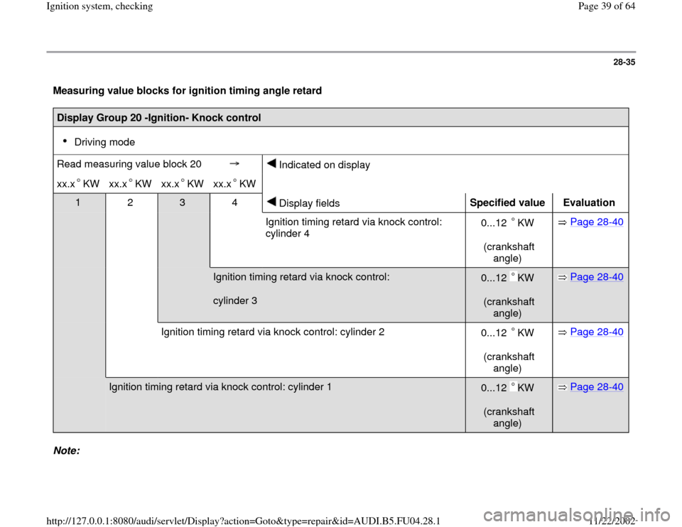
Measuring value blocks for ignition timing angle retard Display Group 20 -Ignition- Knock control
Driving mode
Read measuring value block 20
Indicated on display
xx.x KW
xx.x KW
xx.x KW
xx.x KW
1 2
3 4
Display fields
Specified value
Evaluation
Ignition timing retard via knock control:
cylinder 4 0...12 KW
(crankshaft
angle)
Page 28
-40
Ignition timing retard via knock control:
cylinder 3
0...12 KW
(crankshaft
angle)
Page 28
-40
Ignition timing retard via knock control: cylinder 2
0...12 KW
(crankshaft
angle)
Page 28
-40
Ignition timing retard via knock control: cylinder 1
0...12 KW
(crankshaft
angle)
Page 28
-40
Note:
Pa
ge 39 of 64 I
gnition s
ystem, checkin
g
11/22/2002 htt
p://127.0.0.1:8080/audi/servlet/Dis
play?action=Goto&t
yp
e=re
pair&id=AUDI.B5.FU04.28.1
Page 40 of 64
The displayed digit values in display fields 1 to 4 reflects the actual "ignition timing retard" via knock control from the individual
cylinders. The ignition timing retard occurs via KW (crankshaft angle).
Pa
ge 40 of 64 I
gnition s
ystem, checkin
g
11/22/2002 htt
p://127.0.0.1:8080/audi/servlet/Dis
play?action=Goto&t
yp
e=re
pair&id=AUDI.B5.FU04.28.1
Trending: coolant temperature, wiring, wiring diagram, catalytic converter, buttons, diagram, immobilizer
