ECO mode AUDI A4 1998 B5 / 1.G Brakes Output DTM 03 Workshop Manual
[x] Cancel search | Manufacturer: AUDI, Model Year: 1998, Model line: A4, Model: AUDI A4 1998 B5 / 1.GPages: 66, PDF Size: 0.34 MB
Page 1 of 66
01-149
Output Diagnostic Test Mode
(DTM) (function 03)
Output Diagnostic Test Mode (DTM) is used to
check the function of actuators. Actuators are
also called actors. These are components that
the control module activates when it reacts to the
signals sent by sensors.
"Function of actuators" includes all functions and
properties of an actuator under operating
conditions. This means, for example:
- An electrically operated hydraulic valves that
opens and closes when activated by the control
module.
- The relay of an electrical motor when activated
by the control module. The motor switches on
and carry outs the task.
Before initiating the output Diagnostic Test Mode
(DTM), make sure there are no electrical
malfunctions in the system you wish to test. This
will enable you to recognize any mechanical
problems. Perform a guided troubleshooting
before starting output Diagnostic Test Mode
(DTM) page 01
-19
.
Are you sure there are no electrical malfunctions
in the system? If you have made sure that there
are no electrical malfunctions in the system, you
Pa
ge 1 of 66 Out
put Dia
gnostic Test Mode
(DTM
) (function 03
)
11/20/2002 htt
p://127.0.0.1:8080/audi/servlet/Dis
play?action=Goto&t
yp
e=re
pair&id=AUDI.B5.SU02.01.13
Page 4 of 66
01-151
Notes:
To avoid overloading the components being
checked, they are actuated during the test
sequence for a period of 60 (or 90) seconds.
The actuator test will be terminated if the "
button" is not pressed within this period.
The ABS warning light and the red "brake
system malfunction" symbol blink during the
test.
Pressing the brake pedal repeatedly this
relieves the vacuum in the brake booster. For
this reason, the brake pedal must be pressed
harder in order to achieve the same braking
effect. Your work will be easier if you run the
engine briefly. This will build up vacuum in the
brake booster again.
Pa
ge 4 of 66 Out
put Dia
gnostic Test Mode
(DTM
) (function 03
)
11/20/2002 htt
p://127.0.0.1:8080/audi/servlet/Dis
play?action=Goto&t
yp
e=re
pair&id=AUDI.B5.SU02.01.13
Page 5 of 66
01-152
During the test, the individual test steps are
shown in the second line of the VAG1551
scan tool display. The following
abbreviations are used.
IV = Inlet valve
OV = Outlet valve
LF = Left Front
RF = Right Front
LR = Left Rear
RR = Right Rear
B+ = Battery Positive Voltage (B+) at valve
0V = 0 volts; No voltage at valve
Locked/free = Wheel condition; must be checked
by second technician
Hydr-P = Hydraulic pump
Pa
ge 5 of 66 Out
put Dia
gnostic Test Mode
(DTM
) (function 03
)
11/20/2002 htt
p://127.0.0.1:8080/audi/servlet/Dis
play?action=Goto&t
yp
e=re
pair&id=AUDI.B5.SU02.01.13
Page 18 of 66
01-164
Output Diagnostic Test Mode (DTM)
-
EDL valves/ Hydr-P : B+ Wheel fl/fr lock
Indicated on display: Only significant for troubleshooting on
vehicles with EDL, starting with production deadline of calendar
week 21/1997. For these vehicles, the test step was modified in
parallel to implementation of EBD emergency mode. Prior to
production deadline of calendar week 21/1997, the hydraulic pump is
not activated. This test step does not apply to vehicles without EDL.
The vehicle version, as relates to EBD, can be recognized by checking
the note column under "Check control module version"; page 01
-128
.
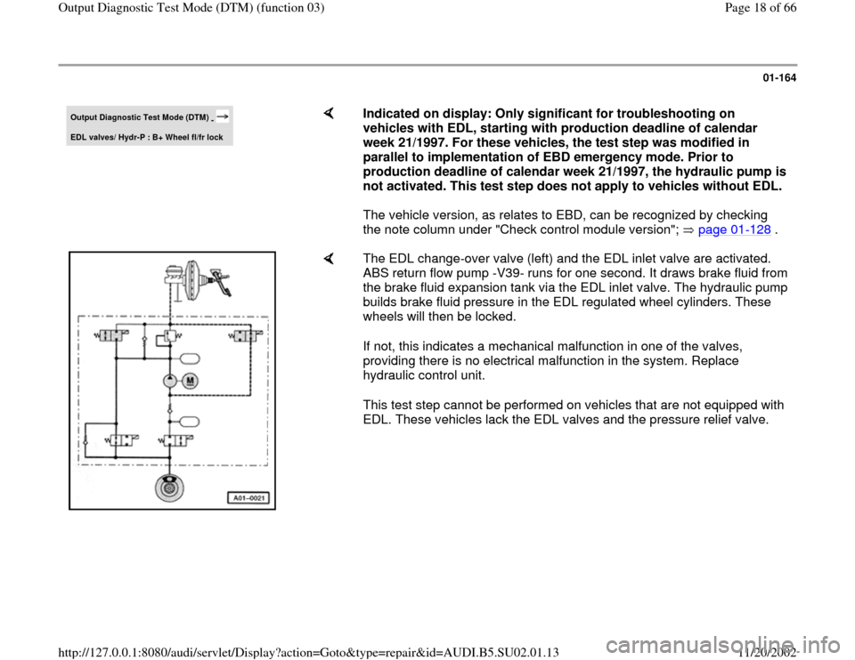
The EDL change-over valve (left) and the EDL inlet valve are activated.
ABS return flow pump -V39- runs for one second. It draws brake fluid from
the brake fluid expansion tank via the EDL inlet valve. The hydraulic pump
builds brake fluid pressure in the EDL regulated wheel cylinders. These
wheels will then be locked.
If not, this indicates a mechanical malfunction in one of the valves,
providing there is no electrical malfunction in the system. Replace
hydraulic control unit.
This test step cannot be performed on vehicles that are not equipped with
EDL. These vehicles lack the EDL valves and the pressure relief valve.
Pa
ge 18 of 66 Out
put Dia
gnostic Test Mode
(DTM
) (function 03
)
11/20/2002 htt
p://127.0.0.1:8080/audi/servlet/Dis
play?action=Goto&t
yp
e=re
pair&id=AUDI.B5.SU02.01.13
Page 20 of 66
01-166
Electrical testing
If the On Board Diagnostic (OBD) sequence
does not provide any indication of the source of
the malfunction, work through all of the
electrical test steps.
If the OBD sequence identifies the source of the
malfunction, only carry out the test steps
recommended in the DTC table (specific
testing).
Test requirements
The "Automatic Test Sequence" was carried
out and it was determined that the
Transmission Control Module (TCM) and
Engine Control Module (ECM) only contain
DTCs relating to ABS/EDL.
- Connect the VAG1551 Scan Tool (ST) and
select the address word 00 with ignition
switched on;
- After completing electrical test, check and
erase DTC memories of Transmission Control
Module (TCM) and Engine Control Module
(ECM).
Pa
ge 20 of 66 Out
put Dia
gnostic Test Mode
(DTM
) (function 03
)
11/20/2002 htt
p://127.0.0.1:8080/audi/servlet/Dis
play?action=Goto&t
yp
e=re
pair&id=AUDI.B5.SU02.01.13
Page 35 of 66
01-180
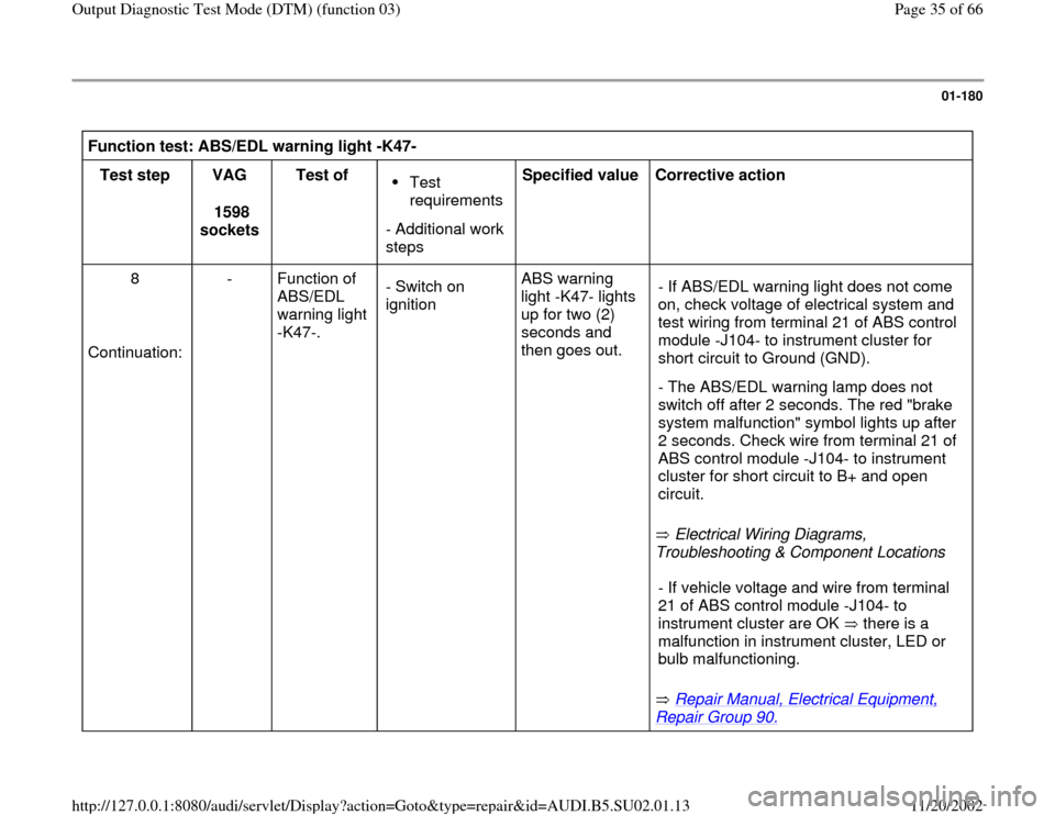
Function test: ABS/EDL warning light -K47-
Test step
VAG
1598
sockets Test of
Test
requirements
- Additional work
steps Specified value
Corrective action
8
Continuation: - Function of
ABS/EDL
warning light
-K47-. - Switch on
ignition ABS warning
light -K47- lights
up for two (2)
seconds and
then goes out.
Electrical Wiring Diagrams,
Troubleshooting & Component Locations - If ABS/EDL warning light does not come
on, check voltage of electrical system and
test wiring from terminal 21 of ABS control
module -J104- to instrument cluster for
short circuit to Ground (GND).
- The ABS/EDL warning lamp does not
switch off after 2 seconds. The red "brake
system malfunction" symbol lights up after
2 seconds. Check wire from terminal 21 of
ABS control module -J104- to instrument
cluster for short circuit to B+ and open
circuit.
Repair Manual, Electrical Equipment,
Repair Group 90.
- If vehicle voltage and wire from terminal
21 of ABS control module -J104- to
instrument cluster are OK there is a
malfunction in instrument cluster, LED or
bulb malfunctioning.
Pa
ge 35 of 66 Out
put Dia
gnostic Test Mode
(DTM
) (function 03
)
11/20/2002 htt
p://127.0.0.1:8080/audi/servlet/Dis
play?action=Goto&t
yp
e=re
pair&id=AUDI.B5.SU02.01.13
Page 39 of 66
01-184
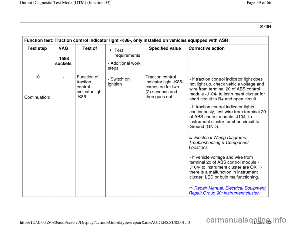
Function test: Traction control indicator light -K86-, only installed on vehicles equipped with ASR
Test step
VAG
1598
sockets Test of
Test
requirements
- Additional work
steps Specified value
Corrective action
10
Continuation: - Function of
traction
control
indicator light
-K86- - Switch on
ignition Traction control
indicator light -K86-
comes on for two
(2) seconds and
then goes out.
Electrical Wiring Diagrams,
Troubleshooting & Component
Locations - If traction control indicator light does
not light up, check vehicle voltage and
wire from terminal 20 of ABS control
module -J104- to instrument cluster for
short circuit to B+ and open circuit.
- If traction control indicator lights
continuously, test wire from terminal 20
of ABS control module -J104- to
instrument cluster for short circuit to
Ground (GND).
Repair Manual, Electrical Equipment,
Repair Group 90; instrument cluster.
- If vehicle voltage and wire from
terminal 20 of ABS control module -
J104- to instrument cluster are OK
there is a malfunction in instrument
cluster, LED or bulb malfunctioning.
Pa
ge 39 of 66 Out
put Dia
gnostic Test Mode
(DTM
) (function 03
)
11/20/2002 htt
p://127.0.0.1:8080/audi/servlet/Dis
play?action=Goto&t
yp
e=re
pair&id=AUDI.B5.SU02.01.13
Page 43 of 66
01-188
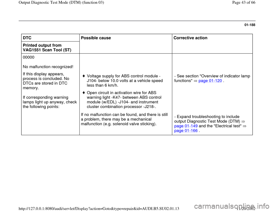
DTC
Possible cause
Corrective action
Printed output from
VAG1551 Scan Tool (ST)
00000
No malfunction recognized!
If this display appears,
process is concluded. No
DTCs are stored in DTC
memory.
If corresponding warning
lamps light up anyway, check
the following points:
Voltage supply for ABS control module -
J104- below 10.0 volts at a vehicle speed
less than 6 km/h. Open circuit in activation wire for ABS
warning light -K47- between ABS control
module (w/EDL) -J104- and instrument
cluster combination processor -J218-. - See section "Overview of indicator lamp
functions" page 01
-120
.
If no malfunction can be found, and there is still
a problem, there may be a mechanical
malfunction (e.g. solenoid valve sticking). - Expand troubleshooting to include
output Diagnostic Test Mode (DTM)
page 01
-149
and the "Electrical test"
page 01
-166
.
Pa
ge 43 of 66 Out
put Dia
gnostic Test Mode
(DTM
) (function 03
)
11/20/2002 htt
p://127.0.0.1:8080/audi/servlet/Dis
play?action=Goto&t
yp
e=re
pair&id=AUDI.B5.SU02.01.13