AUDI A4 2001 B5 / 1.G Technical Features Design And Function
Manufacturer: AUDI, Model Year: 2001, Model line: A4, Model: AUDI A4 2001 B5 / 1.GPages: 88, PDF Size: 10.42 MB
Page 21 of 88
Downloaded from www.Manualslib.com manuals search engine
21
Injector
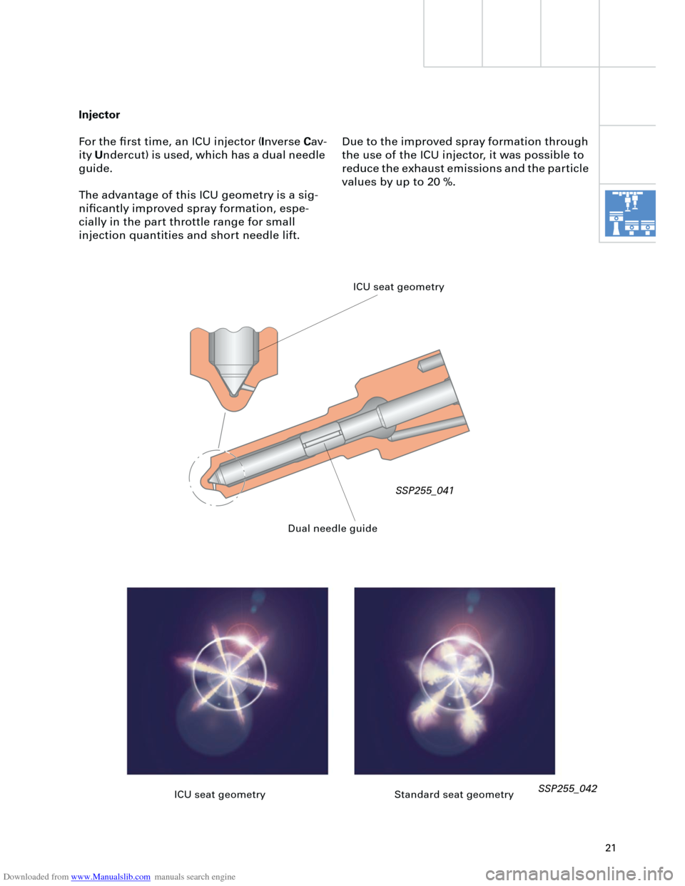
For the first time, an ICU injector (
I
nverse
C
av-
ity
U
ndercut) is used, which has a dual needle
guide.
The advantage of this ICU geometry is a sig-
nificantly improved spray formation, espe-
cially in the part throttle range for small
injection quantities and short needle lift.
SSP255_042
ICU seat geometry
Dual needle guide
Due to the improved spray formation through
the use of the ICU injector, it was possible to
reduce the exhaust emissions and the particle
values by up to 20 %.
ICU seat geometry Standard seat geometry
SSP255_041
Page 22 of 88
Downloaded from www.Manualslib.com manuals search engine
22
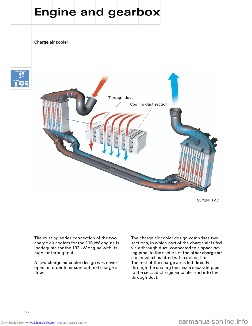
The charge air cooler design comprises two
sections, in which part of the charge air is fed
via a through duct, connected to a space-sav-
ing pipe, to the section of the other charge air
cooler which is fitted with cooling fins.
The rest of the charge air is fed directly
through the cooling fins, via a separate pipe,
to the second charge air cooler and into the
through duct.
Charge air cooler
Engine and gearbox
The existing series connection of the two
charge air coolers for the 110 kW engine is
inadequate for the 132 kW engine with its
high air throughput.
A new charge air cooler design was devel-
oped, in order to ensure optimal charge air
flow.
SSP255_043
Through duct
Cooling duct section
Page 23 of 88
Downloaded from www.Manualslib.com manuals search engine
23
P
R+NDS
Innovations - automatic
gearbox
5-speed 01V automatic gearbox
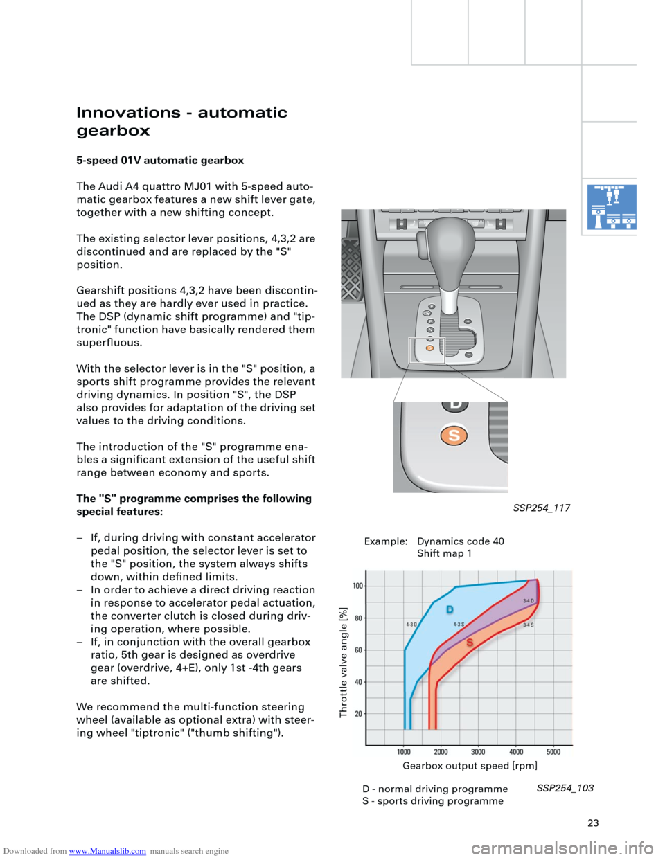
The Audi A4 quattro MJ01 with 5-speed auto-
matic gearbox features a new shift lever gate,
together with a new shifting concept.
The existing selector lever positions, 4,3,2 are
discontinued and are replaced by the "S"
position.
Gearshift positions 4,3,2 have been discontin-
ued as they are hardly ever used in practice.
The DSP (dynamic shift programme) and "tip-
tronic" function have basically rendered them
superfluous.
With the selector lever is in the "S" position, a
sports shift programme provides the relevant
driving dynamics. In position "S", the DSP
also provides for adaptation of the driving set
values to the driving conditions.
The introduction of the "S" programme ena-
bles a significant extension of the useful shift
range between economy and sports.
The "S" programme comprises the following
special features:
– If, during driving with constant accelerator
pedal position, the selector lever is set to
the "S" position, the system always shifts
down, within defined limits.
– In order to achieve a direct driving reaction
in response to accelerator pedal actuation,
the converter clutch is closed during driv-
ing operation, where possible.
– If, in conjunction with the overall gearbox
ratio, 5th gear is designed as overdrive
gear (overdrive, 4+E), only 1st -4th gears
are shifted.
We recommend the multi-function steering
wheel (available as optional extra) with steer-
ing wheel "tiptronic" ("thumb shifting").
Gearbox output speed [rpm]
Throttle valve angle [%]
SSP254_103 SSP254_117
D - normal driving programme
S - sports driving programmeExample: Dynamics code 40
Shift map 1
Page 24 of 88
Downloaded from www.Manualslib.com manuals search engine
24
Special feature:
The countdown from approx. 10 seconds to
return to normal automatic operation is inter-
rupted, in the event that cornering is detected
or the vehicle is in overrun operation.
When normal driving conditions are detected
again, the countdown recommences from
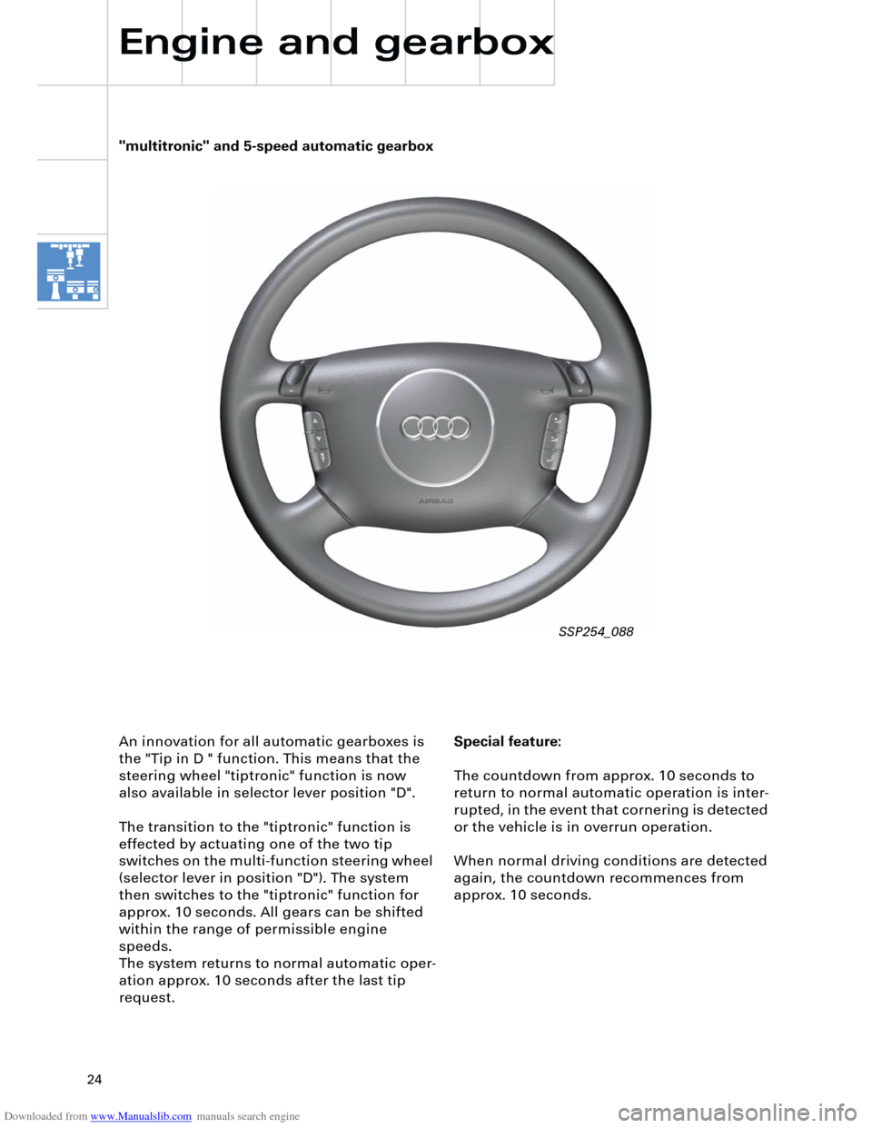
approx. 10 seconds. An innovation for all automatic gearboxes is
the "Tip in D " function. This means that the
steering wheel "tiptronic" function is now
also available in selector lever position "D".
The transition to the "tiptronic" function is
effected by actuating one of the two tip
switches on the multi-function steering wheel
(selector lever in position "D"). The system
then switches to the "tiptronic" function for
approx. 10 seconds. All gears can be shifted
within the range of permissible engine
speeds.
The system returns to normal automatic oper-
ation approx. 10 seconds after the last tip
request.
Engine and gearbox
"multitronic" and 5-speed automatic gearbox
SSP254_088
Page 25 of 88

Downloaded from www.Manualslib.com manuals search engine
25
Notes
Page 26 of 88
Downloaded from www.Manualslib.com manuals search engine
26
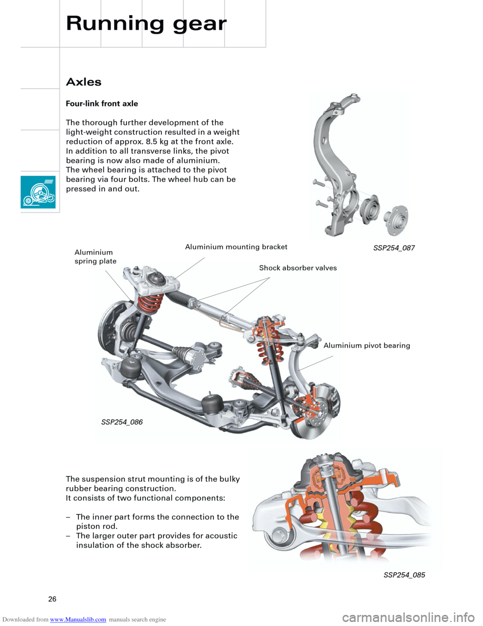
The suspension strut mounting is of the bulky
rubber bearing construction.
It consists of two functional components:
– The inner part forms the connection to the
piston rod.
– The larger outer part provides for acoustic
insulation of the shock absorber.
Axles
Four-link front axle
The thorough further development of the
light-weight construction resulted in a weight
reduction of approx. 8.5 kg at the front axle.
In addition to all transverse links, the pivot
bearing is now also made of aluminium.
The wheel bearing is attached to the pivot
bearing via four bolts. The wheel hub can be
pressed in and out.
Running gear
SSP254_087
Aluminium pivot bearing Aluminium mounting bracket
Aluminium
spring plate
Shock absorber valves
SSP254_086
SSP254_085
Page 27 of 88
Downloaded from www.Manualslib.com manuals search engine
27
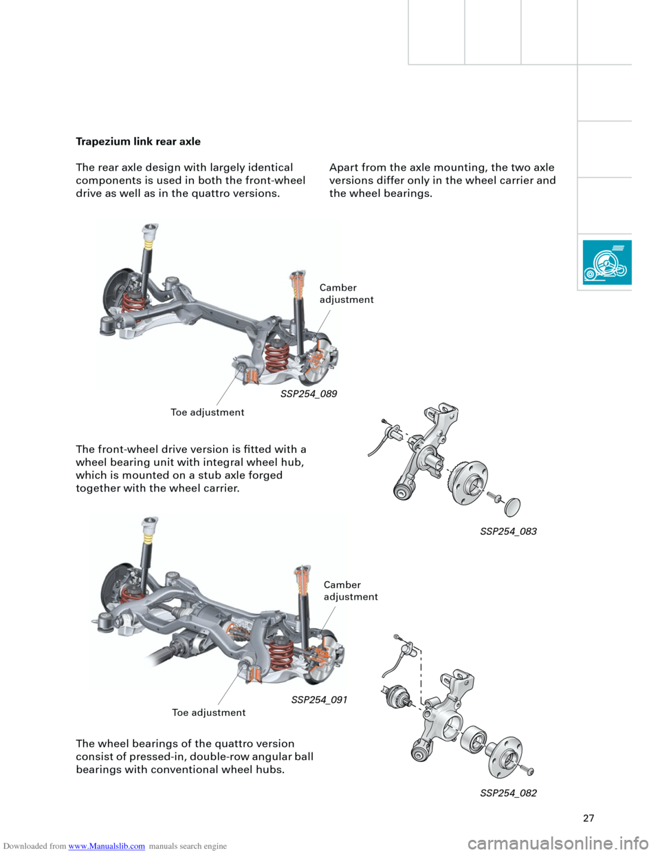
The front-wheel drive version is fitted with a
wheel bearing unit with integral wheel hub,
which is mounted on a stub axle forged
together with the wheel carrier.
Trapezium link rear axle
The rear axle design with largely identical
components is used in both the front-wheel
drive as well as in the quattro versions.
The wheel bearings of the quattro version
consist of pressed-in, double-row angular ball
bearings with conventional wheel hubs.
SSP254_089
SSP254_091
Toe adjustmentCamber
adjustment
SSP254_082 SSP254_083
Apart from the axle mounting, the two axle
versions differ only in the wheel carrier and
the wheel bearings.
Toe adjustment
Camber
adjustment
Page 28 of 88
Downloaded from www.Manualslib.com manuals search engine
28
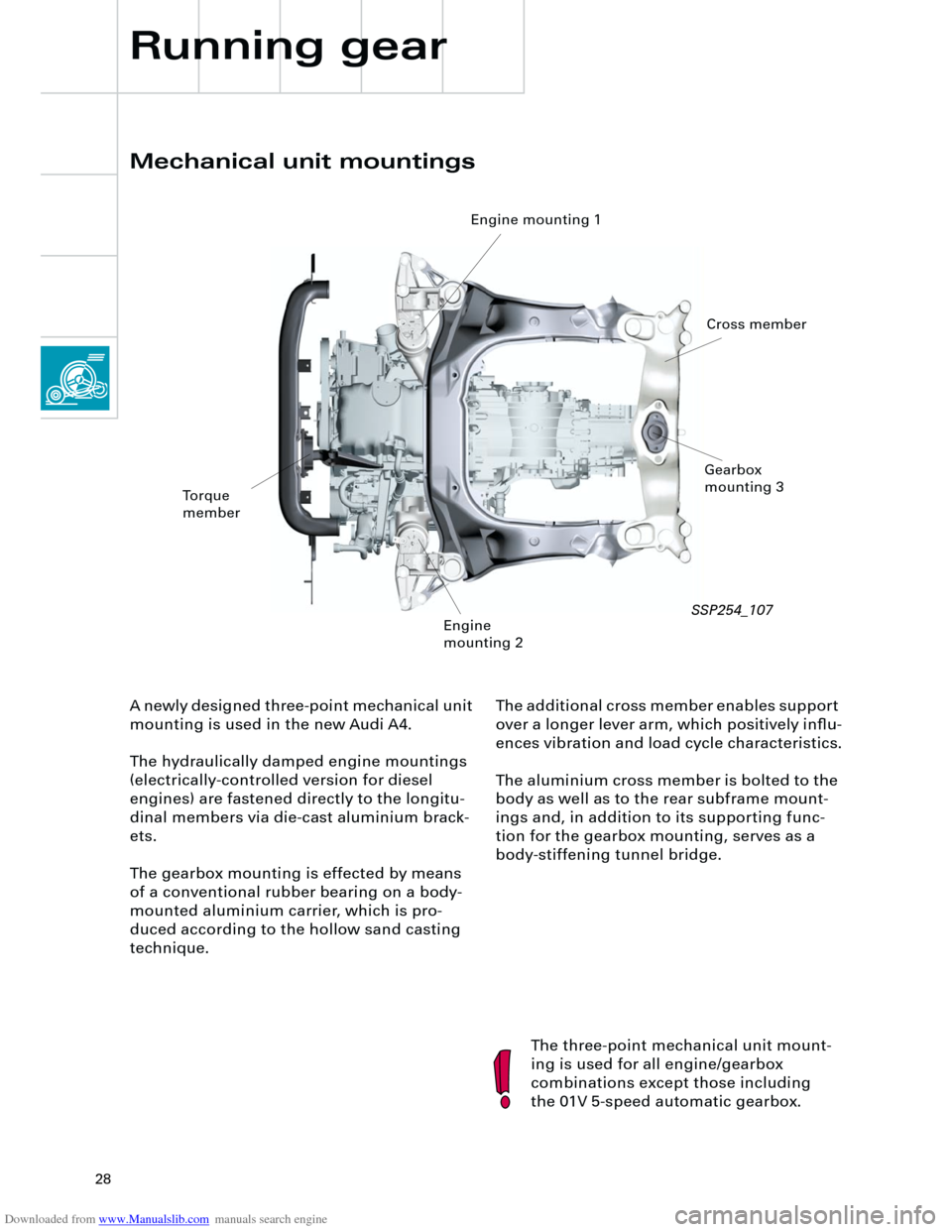
The additional cross member enables support
over a longer lever arm, which positively influ-
ences vibration and load cycle characteristics.
The aluminium cross member is bolted to the
body as well as to the rear subframe mount-
ings and, in addition to its supporting func-
tion for the gearbox mounting, serves as a
body-stiffening tunnel bridge.
Mechanical unit mountings
Running gear
The three-point mechanical unit mount-
ing is used for all engine/gearbox
combinations except those including
the 01V 5-speed automatic gearbox. A newly designed three-point mechanical unit
mounting is used in the new Audi A4.
The hydraulically damped engine mountings
(electrically-controlled version for diesel
engines) are fastened directly to the longitu-
dinal members via die-cast aluminium brack-
ets.
The gearbox mounting is effected by means
of a conventional rubber bearing on a body-
mounted aluminium carrier, which is pro-
duced according to the hollow sand casting
technique.
Torque
member
Engine mounting 1
Engine
mounting 2Gearbox
mounting 3
Cross member
SSP254_107
Page 29 of 88
Downloaded from www.Manualslib.com manuals search engine
29
Brake system
The new Bosch ESP 5.7 is introduced in the
Audi A4. The ESP 5.7 is distinguished by the
following special features:
– The hydraulic unit and control unit form a
single unit.
– The charging pump (actuation of ESP
hydraulic pump V156) is discontinued.
– A brake assistant is included.
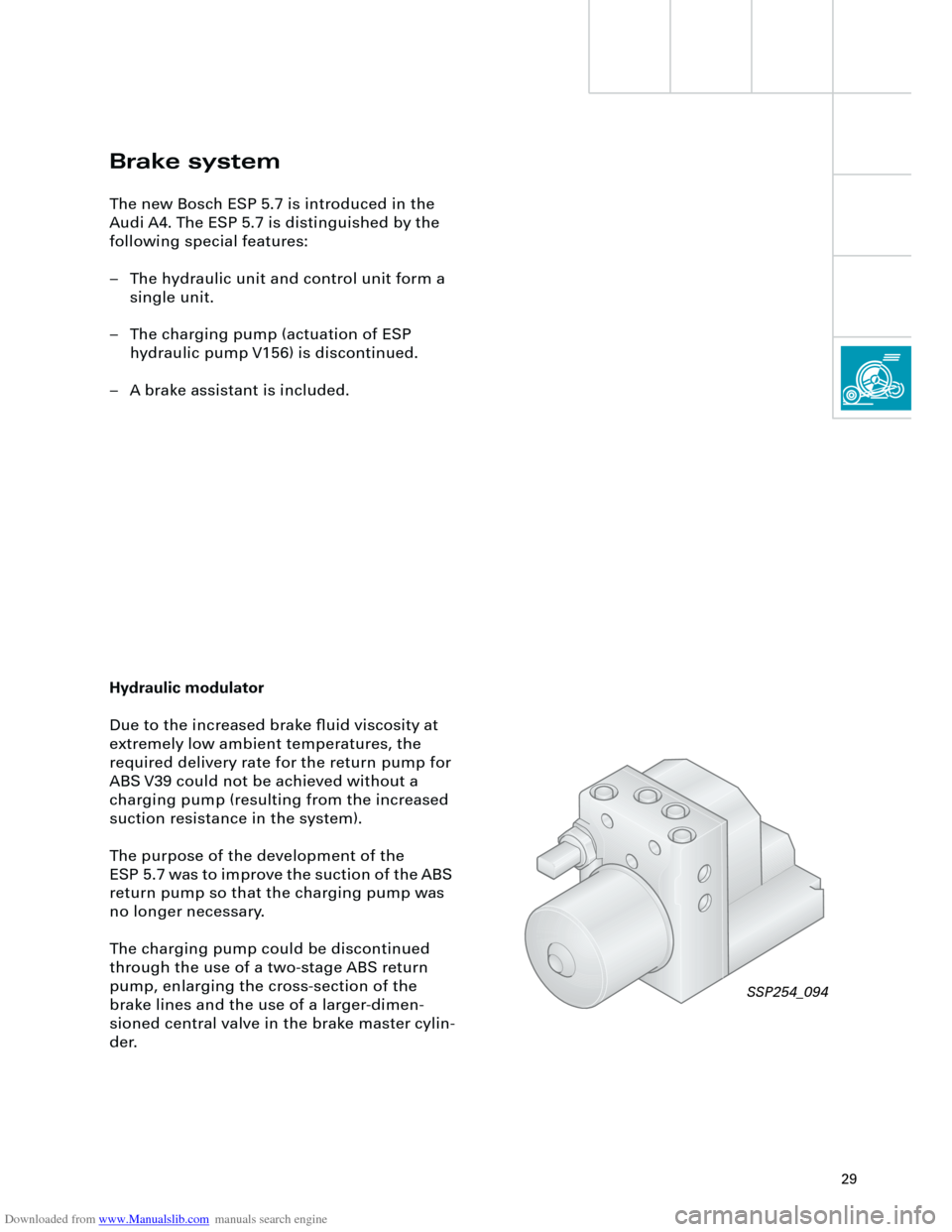
Hydraulic modulator
Due to the increased brake fluid viscosity at
extremely low ambient temperatures, the
required delivery rate for the return pump for
ABS V39 could not be achieved without a
charging pump (resulting from the increased
suction resistance in the system).
The purpose of the development of the
ESP 5.7 was to improve the suction of the ABS
return pump so that the charging pump was
no longer necessary.
The charging pump could be discontinued
through the use of a two-stage ABS return
pump, enlarging the cross-section of the
brake lines and the use of a larger-dimen-
sioned central valve in the brake master cylin-
der.
SSP254_094
Page 30 of 88
Downloaded from www.Manualslib.com manuals search engine
30
UTUTOTOTUT
UTUTOTOTUT
Running gear
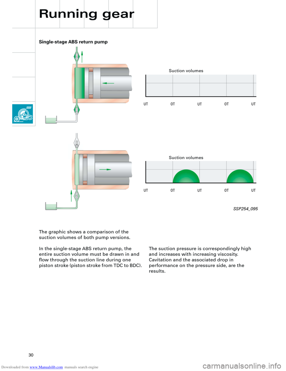
The graphic shows a comparison of the
suction volumes of both pump versions.
In the single-stage ABS return pump, the
entire suction volume must be drawn in and
flow through the suction line during one
piston stroke (piston stroke from TDC to BDC). The suction pressure is correspondingly high
and increases with increasing viscosity.
Cavitation and the associated drop in
performance on the pressure side, are the
results.
Single-stage ABS return pump
Suction volumes
SSP254_095
Suction volumes