AUDI A4 CABRIOLET 2009 Manual PDF
Manufacturer: AUDI, Model Year: 2009, Model line: A4 CABRIOLET, Model: AUDI A4 CABRIOLET 2009Pages: 340, PDF Size: 77.32 MB
Page 71 of 340

forward goes much easier when done by two people. However, if no
assistance is available, you may find it easier to position yourself on
the rear seatbench and lift the power top up by grabbing it at the
center. •
Where is the manual release key stored?
The special key for manually opening the power top
storage bay is located in a compartment behind the fuse
cover.
Fig. 64 Left end-face of
dash panel
Fig. 65 Left end-face of
dash panel: location of
manual release key
-Remove the fuse cover using the ignition key or a screw
driver=:> fig. 64.
- Take the manual key out of its compartment=:> fig. 65. •
Controls and eq uip
ment
Power top
How does the manual release key work?
The manual release key has two distinct configurations
for insertion and actuation.
g
9 :c: ., a,
j ., m
Fig . 66 Release key:
configured for inser
tion
Fig. 67 Release key:
configured for actua
tion
Turn the red handle counter-clockwise as far as poss ible
to configure the release key for insertion =:> fig. 66.
The release key is inserted and engaged in the power top locking
mechanism with the key handle raised. Once inserted and engaged
the key is reset for actuation to lock and unlock the mechanism. •
~ehicle care Technical data
Page 72 of 340
Power top
Step 1: Unlocking the storage bay cover
The locking mechanism for the storage bay cover is
located in the opening for the ski sack in the rear back
rest.
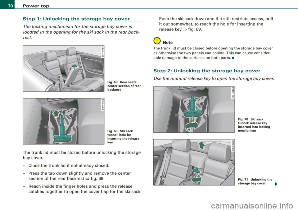
i :r a:> a,
Fig. 68 Rear seats:
center section of rear
backrest
Fig.
69 Ski sack
tunnel: hole for
inserting the release
key
The trunk lid must be closed before unlocking the storage
bay cover.
Close the trunk lid if not already closed.
- Press the tab down slightly and remove the center
section of the rear backrest~ fig. 68.
- Reach inside the finger holes and press the release
catches together to open the cover flap for the ski sack. -
Push the ski sack down and if it still restricts access, pull
it out somewhat, to reach the hole for inserting the
release key~ fig. 69.
0 Note
The trunk lid must be closed before opening the storage bay cover
as otherwise the two panels can collide . This can cause consider
able damage to the surfaces on both parts. •
Step 2: Unlocking the storage bay cover
Use the manual release key to open the storage bay cover.
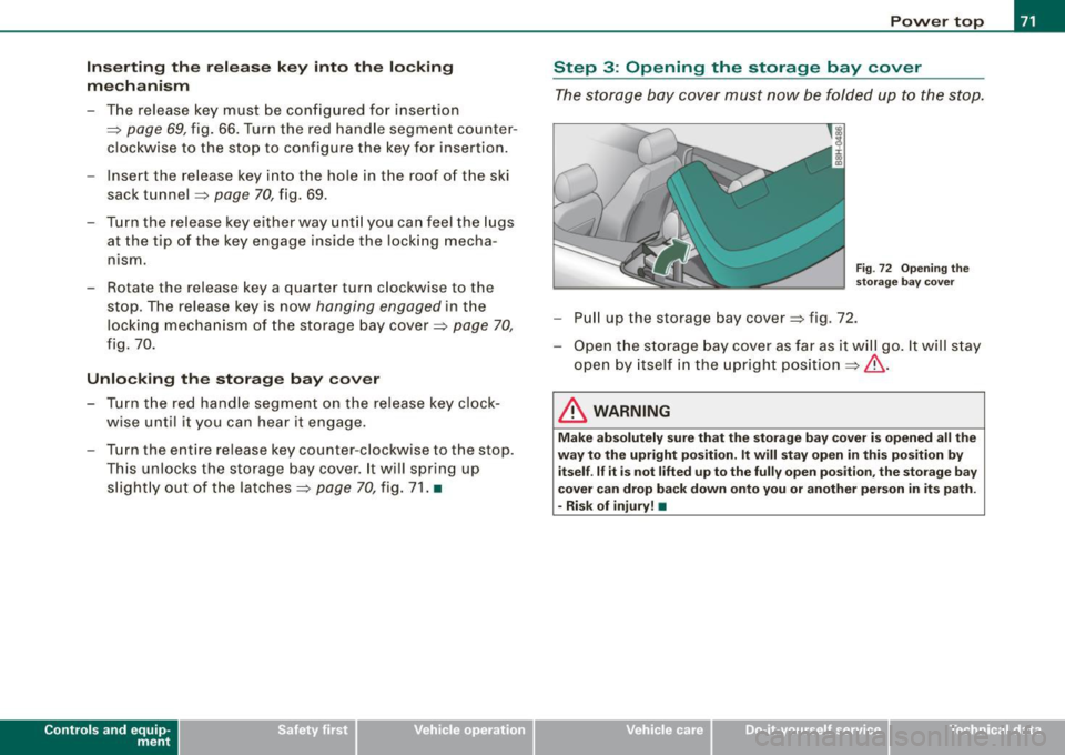
Fig. 70 Ski sack
tunnel: release key
inserted into locking
mechanism
Fig. 71 Unlocking the
storage bay cover
~
Page 73 of 340
Inserting the release key into the locking
mechanism
-The re lease key must be configured for insert ion
=>
page 69, f ig. 66. Turn the red handle segment counter
clockwise to the stop to configure the key for insertion.
- Insert the release key in to the hole in the roof of the ski
sack tunnel :::>
page 70, fig. 69.
- Turn the release key either way until you can feel the lugs
at the tip of the key engage inside the locking mecha
n ism.
- Rotate the release key a quarter turn clockwise to the stop . The release key is now
hanging engaged in the
locking mechanism of the storage bay cover :::>
page 70,
fig. 70.
Unlocking the storage bay cover
- Turn the red handle segment on the release key clock
wise until it you can hear it engage.
- Turn the entire release key counter -clockw ise to the stop.
This unlocks the storage bay cover. It will spring up
slightly out of the latches :::>
page 70, fig. 71. •
Controls and eq uip
ment
Power top
Step 3 : Opening the storage bay cover
The storage bay cover must now be folded up to the stop.
Fig . 72 Opening the
storage bay cover
-Pull up the storage bay cover :::> fig . 72.
- Open the storage bay cove r as far as it will go. It will stay
open by itself in th e upright position =>& .
& WARNING
Make absolutely sure that the storage bay cover is opened all the
way to the upright position. It will stay open in this position by
itself .
If it is not lifted up to the fully open position, the storage bay
cover can drop back down onto you or another person in its path.
- Risk of injury! •
~ehicle care irechnical data
Page 74 of 340
Power top
Step 4: Extending the power top forward
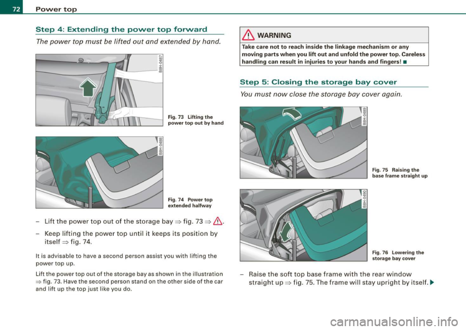
The power top must be lifted out and extended by hand.
Fig. 73 Lifting the
power top out by hand
Fig . 74 Power top
extended halfway
- Lift the power top out of the storage bay=> fig. 73 => &.
Keep lifting the power top until it keeps its position by
itself => fig. 74.
It is advisable to have a second person assist you with lifting the
power top up.
Lift the power top out of the storage bay as shown in the illustration
=> fig. 73. Have the second person stand on the other side of the car
and lift up the top just like you do.
& WARNING
Take care not to reach inside the linkage mechanism or any
moving parts when you
lift out and unfold the power top . Careless
handling can result in injuries to your hands and fingers! •
Step 5: Closing the storage bay cover
You must now close the storage bay cover again.
Fig. 75 Raising the
base frame straight up
Fig . 76 Lowering the
storage bay cover
-Raise the soft top base frame with the rear window
straight up=> fig. 75. The frame will stay upright by itself . .._
Page 75 of 340

- Press down the storage bay to close it=> page 72, fig. 76.
The storage bay cover will slide back into its catches
=>& .
Do not use force when pressing down the storage bay cover. The
cover will not close completely at this stage of the procedure : there
will still be a gap between the body and the storage cover.
& WARNING
Take care that neither you nor any other person get caught with
the hands below the storage bay cover when closing it. Careless
handling can result in injuries to hands and fingers! •
Step 6: Locking the top cover
You must now Jock the storage bay again.
Controls and eq uip
ment
Fig . 77 Locking the
storage bay cover
Locking the storage bay cover
N
! Cl) ID
Power top
Fig. 78 Taking the
manual release key out
-Turn the release key clockwise as far as it will go
=> fig. 77. The storage bay cover will now settle down and
lock in position.
Taking the manual release key out
- Turn the red handle segment on the release key counter
clockwise to the stop.
Turn the entire release key counter-clockwise and then pull it down and out of the mechanism
=> fig. 78. The
storage bay cover is now fully locked. •
~ehicle care irechnical data
Page 76 of 340
Power top
Step 7: Closing the power top
Front and base frame must be brought into position
manually.
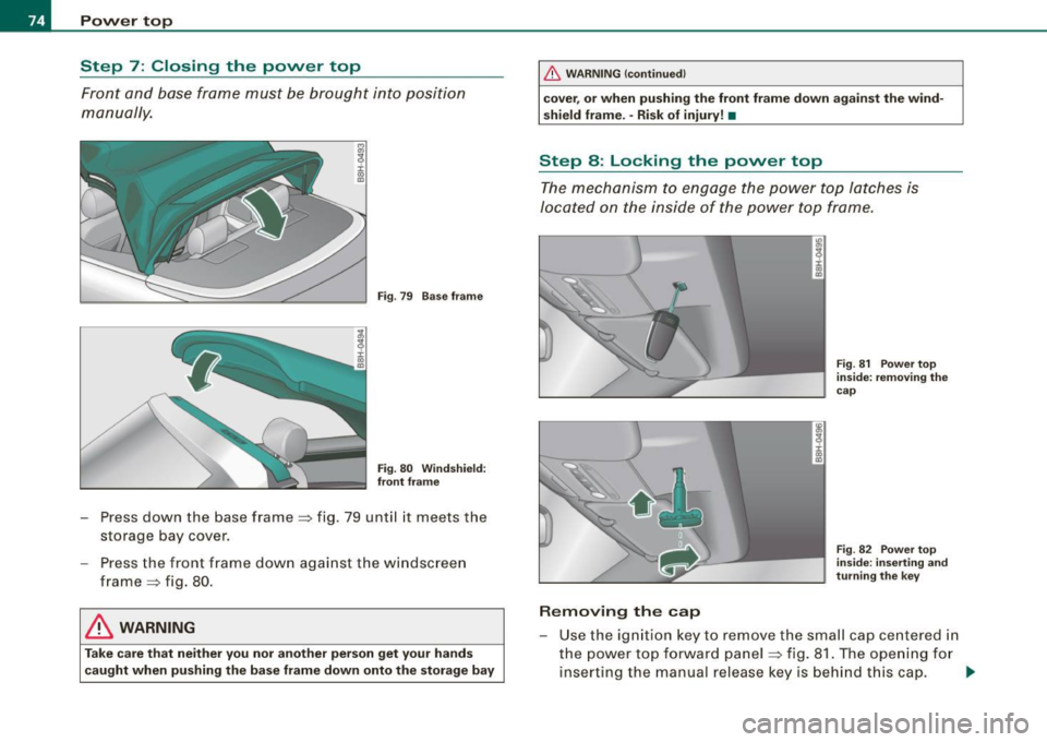
Fig . 79 Base frame
Fig . 80 Windshield:
front frame
- Press down the base frame => fig. 79 until it meets the
storage bay cover.
Press the front frame down against the windscreen
frame => fig. 80.
& WARNING
Take care that neither you nor another person get your hands
caught when pushing the base frame down onto the storage bay
_& WARNING (continued)
cover, or when pushing the front frame down against the wind
shield frame. -Risk of injury! •
Step 8: Locking the power top
The mechanism to engage the power top latches is
located on the inside of the power top frame.
ID
~ i. ., a,
Removing the cap
Fig. 81 Power top
inside: removing the
cap
Fig . 82 Power top
inside: inserting and
turning the key
- Use t he ignition key to remove the small cap centered in
the power top forward panel:::::, fig. 81. The opening for
inserting the manual release key is behind this cap. ..,,
Page 77 of 340
Inse rting the r ele ase ke y i nto th e lock ing
me ch ani sm
- The release key must be configured for insertion
:::;, page 69, fig. 66. If necessary, turn the red hand le
segment counterclockw ise as far as it will go to configure
the key for insertion.
- Insert the release key into the opening:::;,
page 74, fig. 82.
- Turn the release key until you can feel the lugs at the tip of the key engage ins ide the locking mechanism .
- Rotate the release key a quarter turn c lockwise to the
stop. The release key is now
hanging engaged in t he
locking mechanism .•
Step 9: Locking the power top
T he power top has to be locked in position using the
manual release key.
Contro ls and eq uip
ment
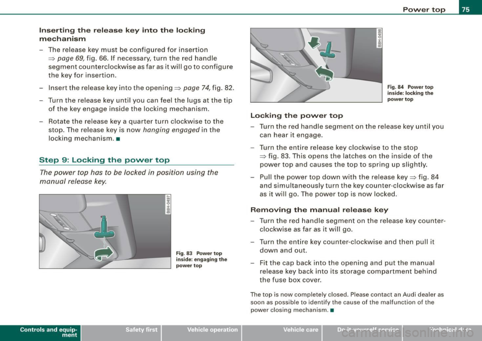
Fi g. 83 Po w er top
i nsi de: engagi ng t he
p owe r to p
Locking th e pow er t op P
o w er top
Fig . 84 Powe r to p
in side: l ocki ng the
powe r to p
- Turn the red handle segment on the release key until you
can hear it engage.
- Turn the entire re lease key clockw ise to the stop
:::;, fig. 83 . This opens the latc hes on the ins ide of the
power top and causes the top to spring up s lightly.
- Pu ll the power top down with the release key:::;, fig. 84
and simultaneously turn the key counter -clockwise as far
as it will go. The power top is now locked.
Remo ving the manual release key
- Turn the red handle segme nt on the release key counter
clockwise as far as it wi ll go.
- Turn the entire key counter-clockw ise and t hen pull it
down and out.
- Fit the cap back into t he opening and p ut the manual
release key back into its storage compartment behind
the fuse box cover .
The top is now completely closed. Please contact an Audi dealer as
soon as possible to identify the cause of the malfunction of the
power c los ing mechanism. •
~ehicle care Technical data
Page 78 of 340

Clear vision
Clear vision
Lights
Switching the headlights on and off ·'t!-·
Fi g. 85 Ins tru ment
pan el: lig ht sw itc h
Fi g.
86 Turn sig nal
lev er: high beam
ON /OFF
All switch pos itions refer to the indentation on the switc h
aligned with the spec if ied symbol. The light switch m ust not
be overt urned past the stops in either direction .
Switching on the side marker lights
- Turn t he light switch light to=> fig. 85
;oo:: .
Switching on the headlights and high beam
- T urn the light switch to ~D.
- Push the turn signa l lever forward towa rds the ins tru -
ment panel => fig. 86, to turn on the high beam, pu ll the
lever back to turn it off=>
page 83.
Swit ching off th e lights
- T urn the light switch to
0 .
The headlights only work when the ignition is switched on . While
starting the engine or when sw itching off the ignition , the head
lights wi ll go of f and only the side marker lights wil l remain lit .
& WARNING
Crashe s can happen when you cannot se e t he ro ad ah ead and
whe n you c annot b e seen by othe r motori sts.
• Alway s turn on the headlights so that you can see ahead and
s o that other s can see y our car fr om the b ack.
[ i ] Tip s
• If you remove the ignition from the ign ition lock whi le the head
lights are still on, a bu zzer will sound as long as the driver 's door is
open to remind you to switch off the lights .
• Always observe the specific local regulations for your area when
to use your lights .•
Page 79 of 340
Applies 10 vehic les: with light senso r package
Sensor activated head -and tail light control
In the "AUTO" position, light sensors monitor outside light
conditions and s witch the head- and t ail lights on and off
as required.
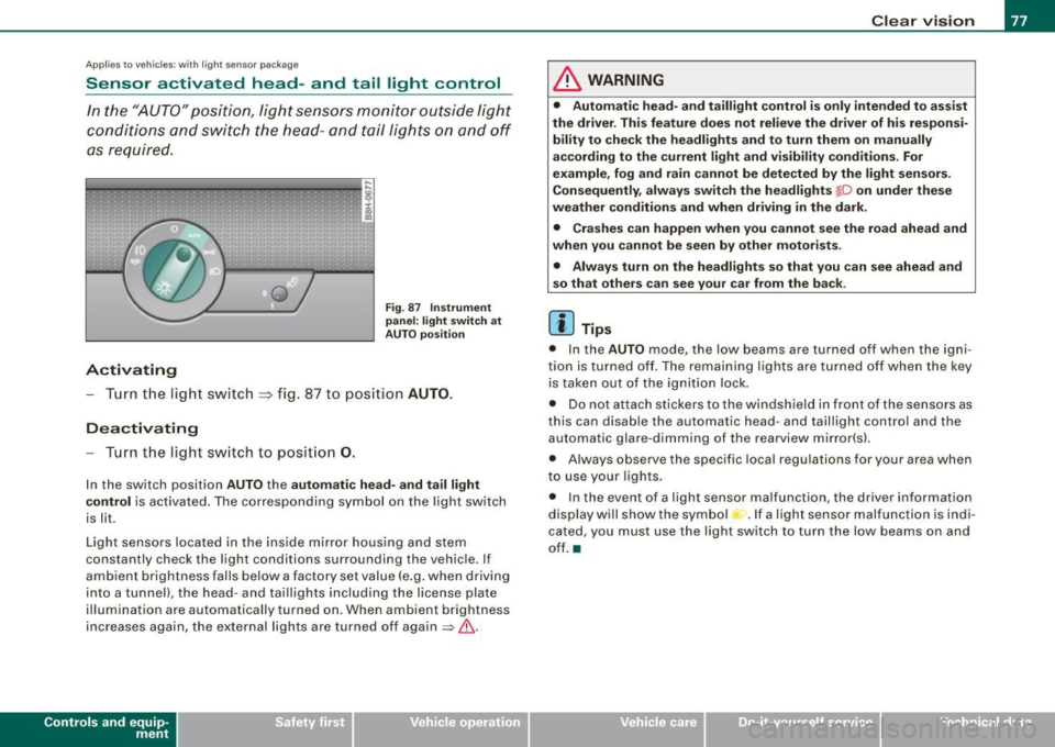
Activating
F ig . 87 Instru men t
p an el: li ght sw itch at
A UTO pos ition
- Tur n the light switch ~ fig. 87 to positi on AUTO.
Deactivating
- Turn the light switch to posit ion 0.
In the switch position AUTO the automati c head -a nd ta il light
contr ol
is activated . The corresponding symbol on the light switch
is lit.
Light sensors located in the ins ide mirror housing and stem
constantly check the light conditions surrounding the vehicle . If
ambient brightness falls below a factory set value (e .g. when driving
into a tunnel), the head -and tai llights including the license plate
illumination are automatically turned on. When ambient brightness
increases again, the external lights are turned off again
=> & -
Contro ls and eq uip
ment
Cle ar v ision
& WARNING
• Autom ati c head - and tailli ght control is only int ended to a ss is t
the driver . Th is feature does not reli ev e th e driver of h is res pon si
bilit y to che ck the headl ights and to turn them on m anuall y
according to the current light and vi sibilit y condition s. For
e xa mple , fo g and r ain cannot be dete cted by the light s en sor s.
Consequently , alw ay s swit ch th e headlights
fD on under the se
we ather condition s and when driving in th e da rk .
• Crashe s can happen when you cannot s ee the road ahead and
w hen you cannot be seen by oth er m otori sts .
• Alway s turn on the headlight s so that you can see ahead and
s o that others ca n s ee your car fr om th e back.
[ i ] Tip s
• In the AUTO mode , the low beams are turned off when the igni
tion is turned off. The remaining lights are turned off when the key is taken out of the ignition lock.
• Do not at tach stickers to the windshield in front of the sensors as
this can disable the automatic head- and taillight contro l and the
automatic glare -dimming of the rearview mirror(s).
• Always observe the specific local regulations for your area when
to use your lights .
• In the event of a light sensor malfunction, the driver information
display wi ll show the sy mbol -.
If a light sensor malfu nction is indi
cated, you must use the light switch to turn the low beams on and
off. a
~ehicle care irechnical data
Page 80 of 340
Clear vision
Ap plies to vehi cles: with d ayt ime running ligh ts
Daytime running lights (DRL) (USA models)
Use the activation switch to turn the daytime running
lights on or off.
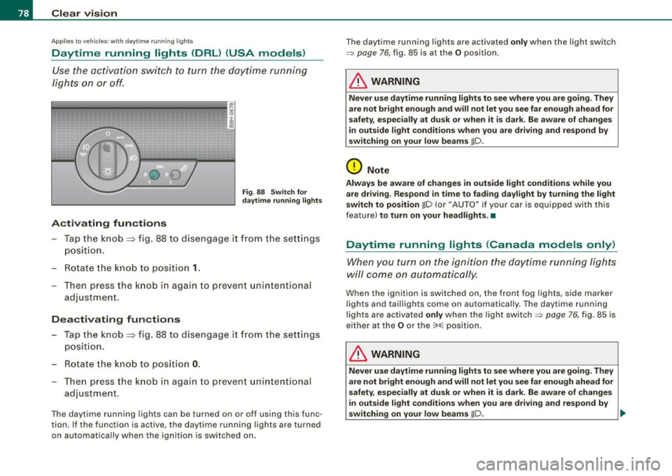
Activating functions
Fi g. 88 Sw itch for
d ayt ime runn ing light s
-Tap the knob ==> fig. 88 to dise ngage it from the sett ings
position.
- Rot ate the k nob to positi on
1.
T hen p ress the knob i n again to prevent unintentional
adjustment .
Deactivating functions
-Tap the knob==> fig. 88 to disengage it from the sett ings
posit ion.
- Rota te th e kn ob to p osition
0 .
- T hen p ress the knob in aga in to p reve nt uninte ntiona l
adjustment .
The daytime running lights can be turned on or off using this func
tion. If the function is active, the daytime running lights are turned
on automatically when the ignition is sw itched on . The daytime running lights are activated
only when the light switch
=>
page 76, fig. 85 is at the O posi tion .
& WARNING
Never u se daytime running lights to see where you are going. They
are not bright enough and will not let you see f ar enough ahead for
s afety , e spe cially at dusk or when it i s dark. Be aware of change s
i n out side light condition s when you are driving and re spond by
s witching on your low beams
@-0.
0 Note
Alway s be aware of change s in outside light conditions while you
are dr iving . Re spond in tim e to fading da ylight b y turning the light
s witch to po sition
@-0 {or "AUTO" if you r car is equipped with this
feature)
to turn on your headlight s.•
Daytime running lights (Canada models only)
When yo u tur n on the igni tion t he da ytime running ligh ts
w ill c ome on au toma tic ally.
When the ignition is switched on , the front fog lights, side marker
lights and taillights come on au toma tica lly . The daytime runn ing
lights are activated
only when the light switch=> page 76, fig. 85 is
e ithe r at the
O or the ~o o:: pos ition.
& WARNING
Never u se dayt ime running lights to see where you ar e going. They
ar e not bright enough and will not let y ou see far eno ugh ahead for
s afet y, espe cially at dusk or when it is dark. Be aware of changes
i n out side light conditions whe n you are dri ving a nd respond by
s witching on your low beam s
@-0. ~