technical data AUDI A5 2008 8T / 1.G Manual PDF
[x] Cancel search | Manufacturer: AUDI, Model Year: 2008, Model line: A5, Model: AUDI A5 2008 8T / 1.GPages: 313, PDF Size: 12.13 MB
Page 145 of 313
Audi parking system143
Controls
Safety
Driving tips
General maintenance
Self-help
Technical data
•
To ensure that the acoustic parking aid works properly, the
sensors and the lens of the reversing camera must be kept clean
and free of snow and ice. Please observe the additional notes from
⇒page 152 onwards.
•
Please refer to the notes on towing ⇒page 147.
Applies to vehicles: with parking system advancedReversing camera (Rear View)
The reversing camera image in the MMI display shows the
area behind the vehicle.
Parking mode
There are two different parking modes available when you park your
vehicle with the help of the reversing camera. These are referred to
as “Parking mode 1” ⇒page 145 and “Parking mode 2” ⇒page 146.
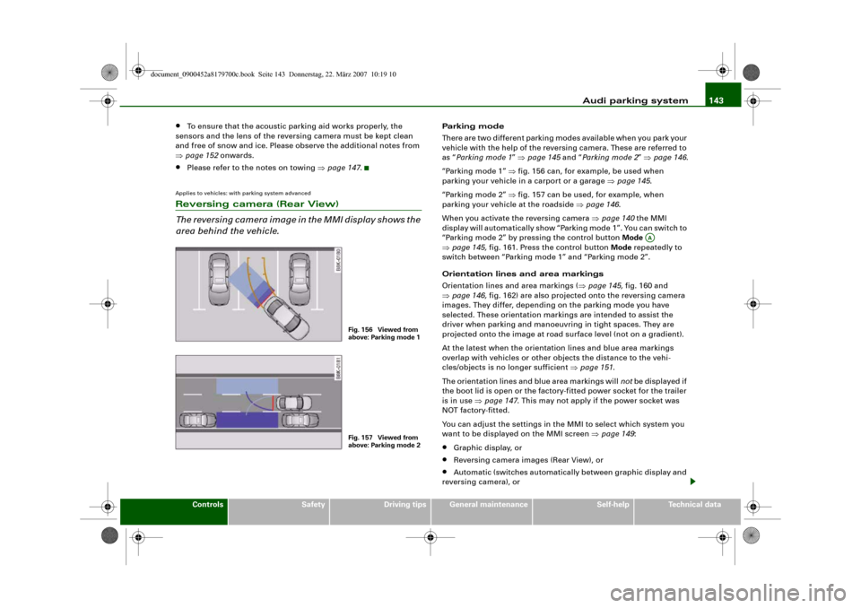
“Parking mode 1” ⇒fig. 156 can, for example, be used when
parking your vehicle in a carport or a garage ⇒page 145.
“Parking mode 2” ⇒fig. 157 can be used, for example, when
parking your vehicle at the roadside ⇒page 146.
When you activate the reversing camera ⇒page 140 the MMI
display will automatically show “Parking mode 1”. You can switch to
“Parking mode 2” by pressing the control button Mode
⇒page 145, fig. 161. Press the control button Mode repeatedly to
switch between “Parking mode 1” and “Parking mode 2”.
Orientation lines and area markings
Orientation lines and area markings (⇒page 145, fig. 160 and
⇒page 146, fig. 162) are also projected onto the reversing camera
images. They differ, depending on the parking mode you have
selected. These orientation markings are intended to assist the
driver when parking and manoeuvring in tight spaces. They are
projected onto the image at road surface level (not on a gradient).
At the latest when the orientation lines and blue area markings
overlap with vehicles or other objects the distance to the vehi-
cles/objects is no longer sufficient ⇒page 151.
The orientation lines and blue area markings will not be displayed if
the boot lid is open or the factory-fitted power socket for the trailer
is in use ⇒page 147. This may not apply if the power socket was
NOT factory-fitted.
You can adjust the settings in the MMI to select which system you
want to be displayed on the MMI screen ⇒page 149:•
Graphic display, or
•
Reversing camera images (Rear View), or
•
Automatic (switches automatically between graphic display and
reversing camera), or
Fig. 156 Viewed from
above: Parking mode 1Fig. 157 Viewed from
above: Parking mode 2
AA
document_0900452a8179700c.book Seite 143 Donnerstag, 22. März 2007 10:19 10
Page 147 of 313
Audi parking system145
Controls
Safety
Driving tips
General maintenance
Self-help
Technical data
WARNING
Please note that objects which are not touching the ground may
appear to be further away than they actually are (e.g. the bumper
of a parked vehicle, a towing bracket or the rear end of a truck). In
this case you should not use the orientation lines for judging the
distance (accident risk).Applies to vehicles: with parking system advancedParking mode 1
“Parking mode 1” can, for example, be used to assist you
when parking in a garage or carport.
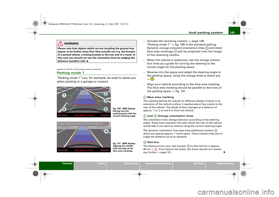
– Activate the reversing camera ⇒page 140.
“Parking mode 1” ⇒fig. 160 is the standard setting.
Dynamic orange-coloured orientation lines and static
blue area markings will be projected onto the image
of the reversing camera.
– When the vehicle is stationary, use the orange orienta-
tion lines as a guide for turning the steering to the
correct angle for the parking space.
– Reverse into the space and adapt the steering angle to
the parking space, using the orange lines to assist you
⇒.
– Align your vehicle according to the blue area marking.
The blue area marking should be parallel to the lines of
the parking space ⇒fig. 161. Blue area marking
The marking behind the vehicle (in different shades of blue) is an
extension of the vehicle outline. It reaches about five metres to the
rear of the vehicle. The shade of blue changes at a distance of
approx. 1m, 2m and 5m from the vehicle.
and Orange orientation lines
The orientation lines change direction according to the steering
angle. These lines represent the path which the rear of the vehicle
would take if you were to reverse using the current steering angle.
The dynamic orientation lines also have additional markers
which are spaced approx. 1 metre apart. These markers help you to
judge the distance up to an obstacle.
Red line
The distance from your rear bumper to the red line is approx.
40 cm ⇒. From here at the latest, the driver should not reverse
any further ⇒page 151.
Fig. 160 MMI display:
Driving into the
parking space with the
correct steering angleFig. 161 MMI display:
Aligning the vehicle
with the help of the
blue area markings
A3
A1
A1A2
A3
A2
A4
A5
document_0900452a8179700c.book Seite 145 Donnerstag, 22. März 2007 10:19 10
Page 149 of 313
Audi parking system147
Controls
Safety
Driving tips
General maintenance
Self-help
Technical data
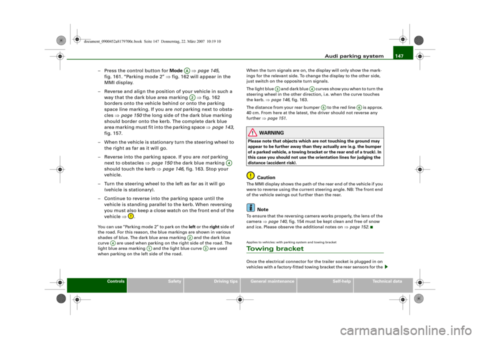
– Press the control button for Mode ⇒page 145,
fig. 161. “Parking mode 2” ⇒fig. 162 will appear in the
MMI display.
– Reverse and align the position of your vehicle in such a
way that the dark blue area marking ⇒fig. 162
borders onto the vehicle behind or onto the parking
space line marking. If you are not parking next to obsta-
cles ⇒page 150 the long side of the dark blue marking
should border onto the kerb. The complete dark blue
area marking must fit into the parking space ⇒page 143,
fig. 157.
– When the vehicle is stationary turn the steering wheel to
the right as far as it will go.
– Reverse into the parking space. If you are not parking
next to obstacles ⇒page 150 the dark blue marking
should touch the kerb ⇒page 146, fig. 163. Stop your
vehicle.
– Turn the steering wheel to the left as far as it will go
(vehicle is stationary).
– Continue to reverse into the parking space until the
vehicle is standing parallel to the kerb. When reversing
you must also keep a close watch on the front end of the
vehicle ⇒.You can use “Parking mode 2” to park on the left or the right side of
the road. For this reason, the blue markings are shown in various
shades of blue. The dark blue area marking and the dark blue
curve are used when parking on the right side of the road. The
light blue area marking and the light blue curve are used
when parking on the left side of the road.When the turn signals are on, the display will only show the mark-
ings for the relevant side. To change the display to the other side,
just switch on the opposite turn signals.
The light blue and dark blue cur v e s s h o w y o u w h e n t o t u r n t h e
steering wheel in the other direction, i.e. when the curve touches
the kerb. ⇒page 146, fig. 163.
The distance from your rear bumper to the red line is approx.
40 cm. From here at the latest, the driver should not reverse any
further ⇒page 151.
WARNING
Please note that objects which are not touching the ground may
appear to be further away than they actually are (e.g. the bumper
of a parked vehicle, a towing bracket or the rear end of a truck). In
this case you should not use the orientation lines for judging the
distance (accident risk).
Caution
The MMI display shows the path of the rear end of the vehicle if you
were to reverse using the current steering angle. NB: The front end
of the vehicle swings out further than the rear.
Note
To ensure that the reversing camera works properly, the lens of the
camera ⇒page 140, fig. 154 must be kept clean and free of snow
and ice. Please observe the additional notes on ⇒page 152.Applies to vehicles: with parking system and towing bracketTo w i n g b r a c k e tOnce the electrical connector for the trailer socket is plugged in on
vehicles with a factory-fitted towing bracket the rear sensors for the
AAA2
A4
A2
A4
A1
A3
A3
A4
A5
A6
document_0900452a8179700c.book Seite 147 Donnerstag, 22. März 2007 10:19 10
Page 151 of 313
Audi parking system149
Controls
Safety
Driving tips
General maintenance
Self-help
Technical data
Applies to vehicles: with parking system plusSwitching graphic display on and off
The settings for the graphic display can be selected on the
sound system or MMI.– Select: Function selector button > Audi parking
system > Display.If you have selected Graphic in the settings, the screen ⇒page 149,
fig. 167 will automatically show the graphic display when the
parking system is activated.
Note
If you change the settings on the sound system or MMI, the changes
will not take effect until the next time you switch on the parking
system.
Applies to vehicles: with parking system advancedSwitching graphic display/reversing camera on and off
The settings for the graphic display and reversing camera
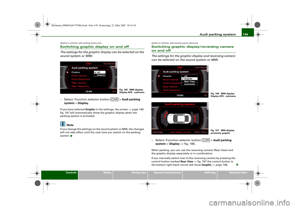
can be selected on the sound system or MMI.– Select: Function selector button > Audi parking
system > Display ⇒fig. 166.When parking, you can use the reversing camera (Rear View) and
the graphic display separately or in combination.
If you manually switch over to the reversing camera by pressing the
control button marked Rear View ⇒fig. 167 the control button in
the bottom right-hand corner will show Graphic ⇒page 146,
Fig. 165 MMI display:
Display APS - submenu
CAR
Fig. 166 MMI display:
Display APS - submenuFig. 167 MMI display:
proximity graphic
CAR
document_0900452a8179700c.book Seite 149 Donnerstag, 22. März 2007 10:19 10
Page 153 of 313
Audi parking system151
Controls
Safety
Driving tips
General maintenance
Self-help
Technical data
•
The parking aid cannot replace the full concentration of the
driver. The driver is always responsible for safety during parking
and other manoeuvres. Always keep a close watch on the area
around the vehicle.
•
When parking or manoeuvring do not rely solely on the MMI
display. Some objects (e.g. narrow posts or bars) may - due to the
resolution of the display screen - not be displayed in a satisfactory
manner or may not be displayed at all.
Applies to vehicles: with parking system advancedNote on distances
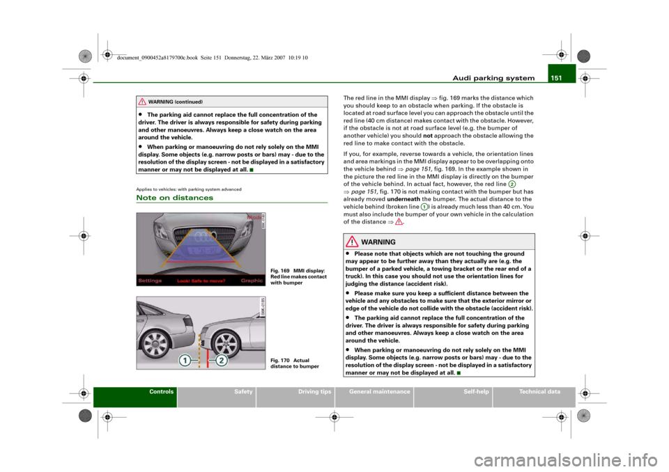
The red line in the MMI display ⇒fig. 169 marks the distance which
you should keep to an obstacle when parking. If the obstacle is
located at road surface level you can approach the obstacle until the
red line (40 cm distance) makes contact with the obstacle. However,
if the obstacle is not at road surface level (e.g. the bumper of
another vehicle) you should not approach the obstacle allowing the
red line to make contact with the obstacle.
If you, for example, reverse towards a vehicle, the orientation lines
and area markings in the MMI display appear to be overlapping onto
the vehicle behind ⇒page 151, fig. 169. In the example shown in
the picture the red line in the MMI display is directly on the bumper
of the vehicle behind. In actual fact, however, the red line
⇒page 151, fig. 170 is not making contact with the bumper but has
already moved underneath the bumper. The actual distance to the
vehicle behind (broken line ) is already much less than 40 cm. You
must also include the bumper of your own vehicle in the calculation
of the distance ⇒.
WARNING
•
Please note that objects which are not touching the ground
may appear to be further away than they actually are (e.g. the
bumper of a parked vehicle, a towing bracket or the rear end of a
truck). In this case you should not use the orientation lines for
judging the distance (accident risk).
•
Please make sure you keep a sufficient distance between the
vehicle and any obstacles to make sure that the exterior mirror or
edge of the vehicle do not collide with the obstacle (accident risk).
•
The parking aid cannot replace the full concentration of the
driver. The driver is always responsible for safety during parking
and other manoeuvres. Always keep a close watch on the area
around the vehicle.
•
When parking or manoeuvring do not rely solely on the MMI
display. Some objects (e.g. narrow posts or bars) may - due to the
resolution of the display screen - not be displayed in a satisfactory
manner or may not be displayed at all.
WARNING (continued)
Fig. 169 MMI display:
Red line makes contact
with bumperFig. 170 Actual
distance to bumper
A2
A1
document_0900452a8179700c.book Seite 151 Donnerstag, 22. März 2007 10:19 10
Page 155 of 313
Audi parking system153
Controls
Safety
Driving tips
General maintenance
Self-help
Technical data
•
Do not allow the camera images in the MMI display to distract
you from watching the traffic.
•
When parking or manoeuvring do not rely solely on the MMI
display. Some objects (e.g. narrow posts or bars) may - due to the
resolution of the display screen - not be displayed in a satisfactory
manner or may not be displayed at all.
•
Only use the reversing camera to assist you if it is supplying
you with a good and clear picture. The quality of the picture could
be impaired by adverse light, dirt on the lens or a defect (accident
risk).
•
If the MMI display is switched on and the picture is obscured or
the area behind the vehicle is not visible (e.g. due to a dirty or
defective lens) you must not use the reversing camera to assist
you when manoeuvring (accident risk).
•
The reversing camera produces two-dimensional images.
Please remember that ridges in the ground, parts protruding on
other vehicles or fixed objects jutting out are all more difficult to
detect on the MMI display screen due to a lack of spatial depth. In
some cases it may not be possible to detect them at all.
•
For safety reasons, you should not use the system if the posi-
tion and installation angle of the camera have been changed, e.g.
in a rear-end collision. Have it checked by a qualified workshop.
•
Only use the reversing camera when the boot lid is completely
closed. Please make sure that there are no objects mounted to the
rear end of the vehicle which could block the view of the reversing
camera.Caution
•
Never remove snow and ice from the lens of the reversing
camera using warm or hot water - danger of cracks appearing on the
lens.
•
Never use abrasive cleaning agents on the lens.WARNING (continued)
document_0900452a8179700c.book Seite 153 Donnerstag, 22. März 2007 10:19 10
Page 157 of 313
HomeLink155
Controls
Safety
Driving tips
General maintenance
Self-help
Technical data
At the operating unit
1. Switch on the ignition (do not start the engine).
2. Press and hold down the two outer HomeLink buttons
⇒page 154, fig. 171 until the indicator diode
⇒page 154, fig. 171 begins to flash after about
20 seconds. This procedure will delete the standard
factory settings and does not need to be repeated when
programming the other buttons.
3. Press the particular HomeLink button which you would
like to program.
4. Wait until the diode begins to flash. The HomeLink
module now remains in training mode for 5 minutes.
5. Now step in front of your vehicle with the original hand-
held transmitter for the garage door opener or any other
device you wish to assign to the HomeLink control
button.
At the radiator grille
6. Hold the original hand-held transmitter at or near the
centre of your car's radiator grille ⇒page 154, fig. 172.
7. Press the activator button on the original hand-held
transmitter.
8. As you do so, watch the turn signals on your vehicle.
HomeLink confirms successful programming by flashing
all four turn signals three times.
9. If the turn signals fail to flash three times, repeat the
procedure with the transmitter held at a different
distance from the radiator grille.
The proper distance between the hand-held transmitter and the
HomeLink module at the radiator grille depends on the system you
want to train. It may require several attempts.
The turn signals will flash once if the time limit for the programming
mode has been exceeded. In this case the programming procedure
needs to be performed again. Repeat the sequence at the operating
unit starting with step 3.
The programming instructions above also apply to the other control
buttons. Start with step 3 if you wish to proceed and program the
other two buttons.
If the garage door or other devices still fail to be activated with the
HomeLink control buttons after programming is completed, it is
possible that these systems might be working with a rolling code
instead of the normal fixed security code. If this is the case, a rolling
code programming is required in addition to the steps described
above. ⇒page 155Applies to vehicles: with HomeLinkRolling code programming
Some devices require rolling code programming of the
HomeLink universal transmitter.Identifying a rolling code
– Press the already programmed HomeLink button again
and hold it down.
–Watch HomeLink diode ⇒page 154, fig. 171. If the
diode starts flashing rapidly and turns into a constant
light after about 2 seconds, this indicates that the device
you wish to operate (e.g. a garage door opener) is
equipped with a rolling code.
– Program the rolling code as follows:
AA
AA
AA
document_0900452a8179700c.book Seite 155 Donnerstag, 22. März 2007 10:19 10
Page 159 of 313
HomeLink157
Controls
Safety
Driving tips
General maintenance
Self-help
Technical data
Applies to vehicles: with HomeLinkRe-programming a button
A HomeLink button can be re-programmed individually
without affecting the other button allocations.At the operating unit in the headliner
– Press and hold down the selected button until the indi-
cator diode ⇒page 154, fig. 171 starts flashing slowly.
At the radiator grille
–Hold the original hand-held transmitter for the garage
door opener or other device directly in front of the radi-
ator grille of your vehicle (at or near the centre)
⇒page 154, fig. 172. The exact distance depends on the
system that you want to program.
– Press the button on the original hand-held transmitter
for the garage door opener or other device.
– As you do so, watch the turn signals on your vehicle.
HomeLink confirms successful programming by flashing
all four turn signals three times.
– If the turn signals fail to flash three times, repeat the
procedure with the transmitter held at a different
distance from the radiator grille.When the turn signals have flashed three times, this means the
device previously stored in HomeLink has been erased and the new
system programmed in its place. To activate the new system, press
the HomeLink button that has just been re-programmed.
Note
It may require several attempts before programming is successful.
When programming a new device, keep the button pressed for at least 15 seconds before trying again with the transmitter in a
different position. Keep watching the turn signals during that
time.
Applies to vehicles: with HomeLinkConformity certificationThe HomeLink universal transmitter is registered in the following
countries under the following certification numbers:Country
Certification number
Andorra
16SEP2003
Belgium
RTT/D/X2064
Denmark
98.3142-266
Germany
D800038K
Finland
FI98080106
France
97619 RD
Gibraltar
RTTE 20754/0087847
Greece
JCI 05JUL2000 RTTE
Great Britain
RTTE 20754/0087847
Republic of Ireland
TRA 24/5/109/5
Iceland
IS-3418-00
Italy
DGPGF/4/341032/TB 0002573
Croatia
SRD-156/03
Luxembourg
L2433/10510-03J
Malta
WT/122/98
Monaco
PC/cp-CI.T55-03/04672
Netherlands
NL99030970
Norway
NO20000026
document_0900452a8179700c.book Seite 157 Donnerstag, 22. März 2007 10:19 10
Page 161 of 313
HomeLink159
Controls
Safety
Driving tips
General maintenance
Self-help
Technical data
document_0900452a8179700c.book Seite 159 Donnerstag, 22. März 2007 10:19 10
Page 165 of 313
Safe driving163
Controls
Safety
Driving tips
General maintenance
Self-help
Technical data
– Make sure that all lights and turn signals are working
properly.
– Check the tyre pressures.
– Make sure that all windows are clean and give good visi-
bility to the outside.
– Secure all luggage and other items carefully ⇒page 77.
– Make sure that no objects can interfere with the pedals.
– Adjust the front seat, head restraint and mirrors
correctly.
– Make sure that the head restraints for all passengers are
adjusted to the correct position.
– Make sure that children are protected with suitable
safety seats and properly worn seat belts ⇒page 185.
– Sit in the correct position in your seat and make sure that
your passengers do the same. ⇒page 70.
– Fasten your seat belt correctly. Make sure that your
passengers do the same ⇒page 170.What affects driving safety?
Safety on the road is directly related to how you drive, and
can also be affected by the passengers in the vehicle.The driver is responsible for the safety of the vehicle and all
its occupants. If your ability to drive is impaired in any way,
you endanger yourself and other road users ⇒. There-
fore:
– Do not let yourself be distracted by passengers or by
using a mobile phone, etc.– Never drive when your driving ability is impaired (by
medication, alcohol, drugs, etc.).
– Obey all traffic regulations and speed limits and always
maintain a safe distance to the vehicle in front.
– Always adjust your speed to suit the road, traffic and
weather conditions.
– Take frequent breaks on long trips. Do not drive for more
than two hours without a stop.
– If possible, avoid driving when you are tired or stressed.
WARNING
•
Distractions while driving or any kind of impairment to your
driving ability increase the risk of accident and injury.
•
Do not store loose objects on the dashboard. These objects
could fly around the interior when the vehicle is moving (under
acceleration or whilst cornering) and distract the driver – this
could lead to an accident.
document_0900452a8179700c.book Seite 163 Donnerstag, 22. März 2007 10:19 10