key AUDI A5 CABRIOLET 2010 Owner's Manual
[x] Cancel search | Manufacturer: AUDI, Model Year: 2010, Model line: A5 CABRIOLET, Model: AUDI A5 CABRIOLET 2010Pages: 364, PDF Size: 86.51 MB
Page 58 of 364

Power top
(I) Tips
• The w ind deflector works best when all of the windows are ro lled
up while driving.
• Only store the wind deflector in the storage bag when it is dry .•
Power top emergency operation
General information
The power top can be closed by hand if there is a malfunc
tion.
- Activate the parking brake.
- Open the windows
- Remove the key from the ignitio n.
Only close the power top manually in an emergency . The best solut ion
is to have yo ur a uthorized Audi dealer correct the ca use of the
malfunct ion .
Powe r top emergency operation consists of the fo llowing steps:
• Unlocking the power top compartm ent cover : The cover on t he
power top compartment must be released by hand.
• Closing the power top : The power top must be lifted out of the
tray and closed.
• Locking the p ower top: The powe r top la tc h es must be locked
with the emergency key.
& WARNING
• When positioning the power top , avoid contact with the
s upport s or other moving part s. Make sure all of the w indows are
lowered . Otherwise you could pi nch your hand s.
& WARNING (contin u ed )
• Never drive when the powe r top i s not locked correctly. The
wind from dr iving coul d caus e the po wer top to open . Thi s can
re sult in injurie s and damage to the vehicle.
(I) Tips
Have a second person assist when closing the power top. Positioning
the power top is easie r whe n there is a second perso n to help. •
Step 1: Unlocking the power top
compartment cover
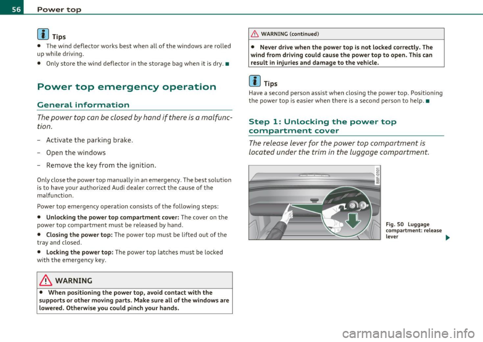
The release lever for the po wer top compartment is
located under the trim in the luggage compartment.
-
---
Fig . 50 L uggage
c omp artment : re lease
leve r ...
Page 59 of 364

Fig. 51 Luggage
compartment: side
trim
- Open the luggage compartment lid. The emergency
release can be used if the luggage compartment lid will
not open =>
page 47.
-Reach your finger into the gap behind the trim near the
center of the vehicle.
- Pull the release lever down to release the power top
compartment cover=>
page 56, fig. SO.
-Open the left side trim and press the yellow lever in the
direction of the arrow=>
page 57, fig. 5 l.
- Remove the emergency key from the compartment on the
left side =>
page 57, fig. 51 @ .
Open the right side trim and press the yellow lever in the
direction of the arrow . •
Con tro ls a nd e quip
m en t Vehicle
OP-eration
Power top
Step 2: Lifting the power top compartment
cover out
Fig. 52 Luggage
compartment lid
completely open
Fig. 53 Storage bay
cover partially open
-Press the luggage compartment lid in the direction of the
arrow => fig. 52.
- Raise the power top compartment cover out of the power
top tray and hold it in place=> fig. 53 =>
&.
Have a second person assist when raising the power top compart
ment cover. That person should stand on the opposite side of the
vehicle and perform the same steps.
Vehicle care Do-it-yourselt service iTechnical data
Page 60 of 364

Power top
& WARNING
When raising the power top compartment cover, avoid contact
with the supports or other moving parts. Otherwise you could
pinch your hands. •
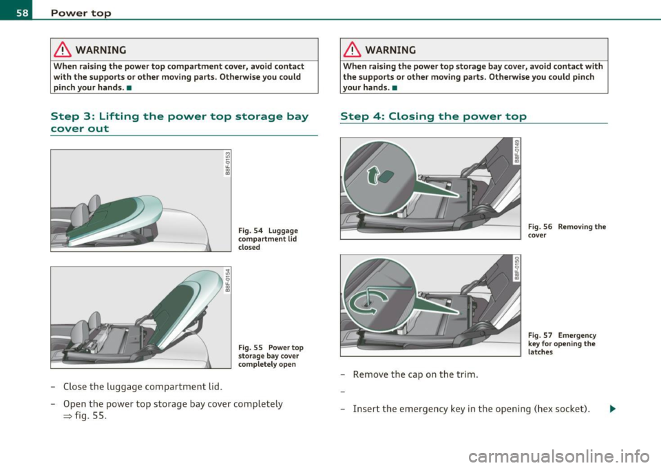
Step 3: Lifting the power top storage bay
cover out
-Close the luggage compartment lid.
Fig. 54 Luggage
compartment
lid
closed
Fig . 55 Power top
storage bay cover
completely open
- Open the power top storage bay cover completely
=> fig. 55.
& WARNING
When raising the power top storage bay cover, avoid contact with
the supports or other moving parts. Otherwise you could pinch
your hands. •
Step 4: Closing the power top
-Remove the cap on the trim.
Fig. 56 Removing the
cover
Fig. 57 Emergency
key for opening the
latches
- Insert the emergency key in the opening (hex socket).
Page 61 of 364

-Turn the release key counterclockwise until it stops to
open the latch.
- Remove the emergency key. •
Step 5: Closing the power top
The power top must be positioned by hand.
Fig. 58 Power top
partially open
Fig . 59 Windshield:
Power top
- Raise the power top out of the tray=> & in "Step 2:
Lifting the power top compartment cover out" on
page 57.
- Pull the power top out completely .
- Press the power top onto the windshield frame~ fig. 59.
Contro ls a nd e quip
m en t Vehicle
OP-eration
Power top
Have a second person assist when positioning the power top. That
person should stand on the opposite side of the vehicle and perform
the same steps.
& WARNING
• When positioning the power top, avoid contact with the
supports or other moving parts. Otherwise you could pinch your
hands.
• When pressing the power top down onto the windshield frame,
make sure that you do not pinch yourself or anyone else. •
Step 6: Retracting the power top
compartment cover
The power top compartment cover must be retracted by
hand.
Fig. 60 Power top
raised
- Raise the rear of the power top and hold it in place
=> fig. 60 (D => & in "Step 2: Lifting the power top
compartment cover out" on
page 57.
- Slide the power top compartment forward until it reaches
the end position => fig. 60
@. Release the power top. ..,
Vehicle care Do-it-yourselt service iTechnical data
Page 62 of 364

Power top
& WARNING
Do not pinch yourself or others when closing the power top
compartment. •
Step 7: Locking the power top
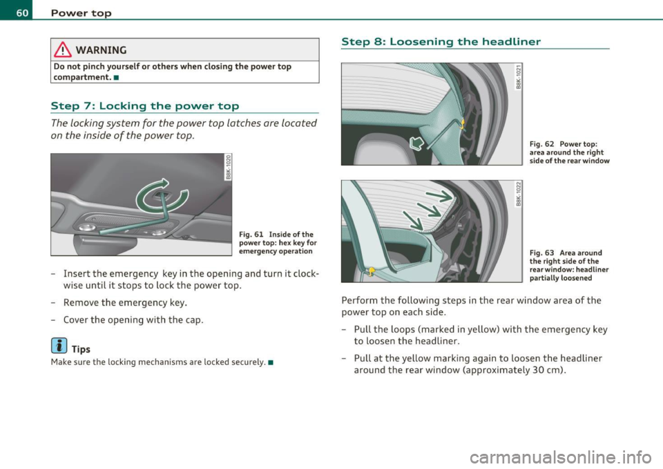
The locking system for the power top latches are located
on the inside of the power top.
Fig. 61 Ins ide of the
power top: hex key for
emergency operation
- Insert the emergency key in the opening and turn it clock
wise until it stops to lock the power top.
- Remove the emergency key.
- Cover the opening with the cap.
[I] Tips
Make sure the locking mechanisms are locked securely. •
Step 8 : Loosening the headliner
Fig. 62 Power top :
area around the right
side of the rear window
Fig. 63 Area around
the right side of the
rear w indow: headliner
part ially loosened
Perform the following steps in the rear window area of the
power top on each side.
- Pull the loops (marked in yellow) with the emergency key
to loosen the headliner.
- Pull at the yellow marking again to loosen the headliner
around the rear window (approximately 30 cm).
Page 63 of 364

Step 9: Securing the latch
Fig. 64 Rear of th e
power top: Se curing
th e latch
The latches must be secured on the left and right sides of the
vehicle.
- Pull the power top headliner to the side in the area around
the rear headrests to secure the latches=> fig. 64 =>
& in
"Step 2: Lifting the power top compartment cover out" on
page 57.
- Then remove the emergency key and insert the short end
into the power top support at the yellow marking.
- Press the emergency key in the direction of the arrow
=> fig. 64
0 until the latc h is secure .
& WARNING
Do not pin ch yourself or othe rs when clo sing the power top
c ompa rtment. •
Con tro ls a nd e quip
m en t Vehicle
OP-eration
Power top
Vehicle care Do-it-yourselt service iTechnical data
Page 65 of 364

& WARNING
Automatic headlights are only intended to assist the driver. They
do not relieve the driver of his responsibility to check the head
lights and to turn them on manually a ccording to the current light
and visibility conditions . For example , fog cannot be detected by
the light sensors . So always switch on the headlights under these
weather conditions and when driving in the dark
tD .
[ i J Tips
• Th e light sensor for head light control is located in the rea r view
m irror mount. You shou ld therefore not app ly any st ickers to the
windshield in th is area in order to prevent m alfunct ions or fa ilure s.
• Th e sensitivity level fo r the light senso r se t a t the factory can be
changed in the MMI menu ~
page 64 in the automatic d riving lights
fu nction .
• When you remove your key from the ign ition wh ile the veh icle's
ligh ts ar e tu rned on, a bu zzer sounds as long as the d river 's door is
open.
• Please obey all laws when using the lighting systems described
here .
• The coming home/ leav ing home fu nction is avai lab le o nly with the
switch in the AU TO position. •
Contro ls a nd e quip
m en t Vehicle
OP-eration
Applies to vehicl es: with fog lights
Fog Lights
Clear vision
Fig . 66 Fo g light
s witch
- To t urn o n the fo g lights tD, press butto n (D:::} fig. 66.
- To turn o n the rear fog lights
0$, press butt on @ .
Fog lights
The side marker lights or low beams must be sw itched on . When the
fog lights a re switc hed on, the green check lig ht at the edge of the
switch comes on .
I f automat ic dr iv ing light cont rol AUTO is act ivated , the low beams
a re switched on whe n the fog ligh ts are turned on.
Rear fog lights
Lo w beam s or sid e ma rke r lig hts wi th f og l igh ts mus t be t urne d o n.
Wh en the rea r fog l ights are turned o n, the y ellow check light at the
edge o f the swi tch comes on .
0 Note
The rea r fog lig hts sho uld only be turned on in accor dance w it h traffic
reg ulation, as t he lights are brig ht for fo llow ing traffic .•
Vehicle care Do-it-yourselt service iTechnical data
Page 70 of 364

Clear vision
0 Note
Do not use the high beam or headlight flasher in if you know that
these could be blinding oncoming traffic. •
Interior lights
Interior lights
The interior lights include the reading lights for the driver
and the front passenger.
Activat ing door contact circuit
F ig . 71 Sect ion from
head liner: Interio r
lights
- Press the button @. The LED in the button illuminates.
Dea ctiv ating door contact circuit
- Press the button @. The LED in the button goes out.
Front r eading lights ~
- Press one of the switches @ to turn the right or left
reading light on or off.
With the door contact circuit, the interior lights turn on as soon as
you unlock the vehicle or open the doors. The interior lights are also turned on when the
ignition key is removed. The lights turn off about
30 seconds after the doors are closed . When the vehicle is locked or
when the ign ition is turned on, the inter ior lights are turned off.
When a door is open, the interior lights are turned off after about 10
m inutes to prevent battery dra ining.
The brightness of the lights is controlled automatically by a dimmer
when they are sw itched on and off. •
Rear interior lights
There are reading lights in the rear for the passengers.
,...
-0 0
"' 0, a,
Fig. 72 Headliner:
Rea r read ing lights
The reading lights are switched on and off using the buttons ~~-•
Page 76 of 364

Clear vision
Memory for exterior mirrors*
On vehicles with memory for the drive r's seat, the curren t sett ing for
t he exter io r mir rors is automatically stored a long w it h t he seat posi
tion ~
page 80.
Tilt funct ion for the passenger's mirror* (only with
memory for exterior mirrors)
W hen the reverse gear is engaged , th e mirror su rface t ilts downwa rd
slightly if the setting is for the passenger 's mirror (knob in position
@ ~ page 73, fig . 78) . T hi s allows you to see the curb dur ing pa ralle l
par king .
T he mir ror r etur ns to it s in iti al position as soon as reverse gear is
disengaged and ve hicle speed is above about 9 mph (15 km/h). The
m irro r also retu rn s t o its in itia l pos it ion i f th e swi tch is moved to the
dr iver's outside mirror © or the ignition is sw itched off.
If t he position of t he mir ro r su rface is changed on a ti lted mirror, this
new position will be automatically assig ned to the remote key when
the vehicle is taken out of reverse gear.
0 Note
Curved mirror su rfaces (convex or spherica l*) increase your fie ld of
view. Remembe r th at veh icles o r o the r object s will appear sm alle r
and fart her away than when seen in a flat m irro r. If you use this
m irror to est ima te dis tanc es o f following vehicles when cha nging
lanes, you cou ld estimate incorrect ly and cause an accident .
[I] Tips
If there should be a malfu nction in the electrical system, you can st ill
a djus t the ou ts id e mir rors by pressing the edge o f the m irro r.•
A pp lies to vehicles: with aut omat ica lly adj usting outs id e m irr ors
Automatic dimming for the outside
mirrors
Th e o utside mirrors dim at the same time as the inside m irror. Whe n
the ignition is switched o n, the mirrors a utomatically dim depending
on the a mou nt of light s triki ng t he m irro rs (su ch as he adlights
shining into the veh icle from the rear) .
W hen the inter io r li ght ing is switche d on and when reverse gear is
engaged, the m irro rs a re switched back to their original brig htn ess
(not dimmed) .
& WARNING
Broken gla ss of automatic dimming mirror can cause electrolyte
fluid leakage. Electrolyte fluid can irritate skin, eyes, and respira
tory sy stem.
• Repeated or prolonged exposure to electrolyte can cause irrita
tion to the re spiratory system, especially among people with
asthma or other respiratory conditions . Get fresh air immediately
by leaving the vehicle or , if that is not po ssible , open window s and
doors all the way.
• If electrolyte gets into the eye s, flush them thoroughly with
large amounts of clean water fo r at least 15 minutes; medical
attention i s recommended .
• If electrolyte contacts skin , flush affected area with clean
water for at lea st 15 minute s and then wash affected area with
soap and water; medical attention is recommended. Thoroughly
wash affected clothing and shoes before reu se.
• If swallowed and person is conscious, r inse mouth with water
for at least 15 minutes . Do not induce vomiting unles s instru cted
to do so by medical professional. Get medical attent ion immedi-
ately .
~
Page 81 of 364

Adjusting the curvature of the lumbar support
- Push the switch p late @forward or backward to increase
or red uce the curvature .
Adjusting the height of the lumbar support
-Push the sw itch p late @ up or down to position the curva
ture higher or lower.
Fore-and-aft adjustment
- Push th e switc h® forward or backward~ pag e 78,
fig . 81.
Adjusting seat height
- Pull or push the switch ® up or down.
Front seat cushion up/ down
-Press th e sw itch ® at the fr ont up or down .
Rear seat cushion up / down
- Press t he switch ® at the rear up or down.
Adjusting seat back angle
-Push th e switc h @ forwa rd or backwar d.
Head restraint height adjustment*
-Press the switch © from up to down or t he ot her way.
Lengthening or shortening upper thigh
support*
- Lift the button @ under the seat cus hion . The front sea t
cushion moves fo rward u nder spring force .
Control s and equ ip
m ent Vehicle OP-eration
Seats and storage
-Push the seat c ushion back w hen you have f in ished using
i t.
& WARNING
• Adjust the driver 's seat only when the vehicle is stationary . You
risk an accident otherw ise.
• The power adjustment for the front seat s al so works with the
ignit ion switched off or with the ignition key removed. For this
reason, children should never be left unattended in the vehicle -
they could be injured!
• Exerci se caution when adjusting the seat height . Unsupervised
or careless seat adjustment can pi nch fingers or hands causing
injuries .
• While the vehicle is mo ving , the seat bac ks of the front seats
mu st not b e inclined to o far to the rear bec ause the effectiveness
of the safety belts and the airbag system is se verely compromised
- there is a risk of injury .•
Easy entry function
The easy entry function makes it easier for the rear
passengers to enter and leave the vehicle.
Vehicle care
... N 0
~
~
F ig . 82 D riv er 's se at:
C ont ro ls for e asy e ntry
assi st
~
Do-it-yourselt service iTechnical data