AUDI A5 COUPE 2010 Owners Manual
Manufacturer: AUDI, Model Year: 2010, Model line: A5 COUPE, Model: AUDI A5 COUPE 2010Pages: 360, PDF Size: 84.39 MB
Page 331 of 360
________________________________________________ E_ m_ e_r ,,::g c..e_ n _ c..::y;._ s_ i_t _u _a_ t_ i_o _n_ s _ ___.ffllll
block itself. If the battery that is being charged does not vent to the
outside, escaping battery gas could ignite and explode! •
Emergency towing with commercial
tow truck
General hints
Your Audi requires special handling for towing.
The following information is to be used by commercial tow truck
operators who know how to operate their equipment safely.
• Never tow your Audi , towing will cause damage to the engine
and transmission.
• Never wrap the safety chains or winch cables around the brake
lines.
• To prevent unnecessary damage, your Audi must be transported
with a flat bed truck.
• To load the vehicle on to the flat bed, use the towing loop found
in the vehicle tools and attach to the front or rear anchorage
~ page 329 and ~ page 330.
& WARNING
A vehicle being towed is not safe for passengers. Never allow
anyone to ride in a vehicle being towed, for any reason. •
Front towing loop
Do not install the front towing loop until it is needed.
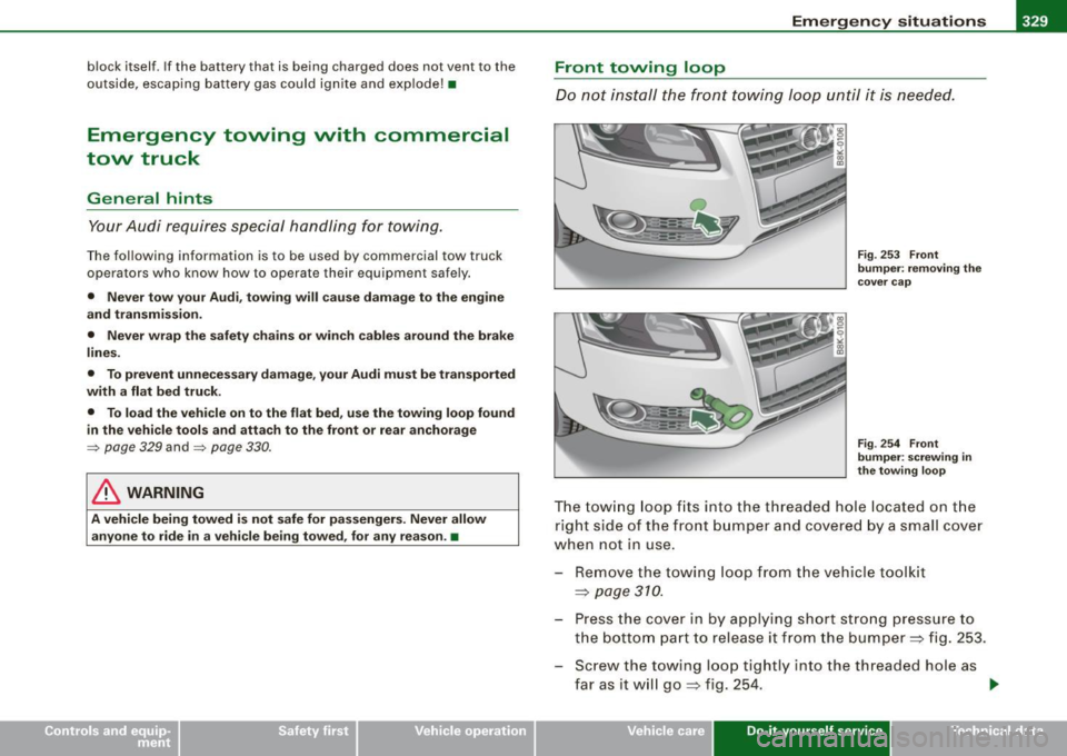
Fig. 253 Front
bumper: removing the
cover cap
Fig . 254 Front
bumper: screwing in
the towing loop
The towing loop fi ts into the thread ed hole located on the
r ight side of the front bumper and covered by a small cover
when not in use.
- Remove the towing loop from the vehicle toolkit
~ page 310.
- Press the cover in by applying short strong pressure to
the bottom part to release it from the bumper~ fig. 253.
- Screw t he towing loop tightly into the threaded hole as
far as it will go
~ fig. 254. ~
Vehicle care Do-it-yourself service irechnical data
Page 332 of 360
IIIII...__E_ m _ e _r.;:g '-e_ n_ c-=y _ s_ i_t _u _a _t_ i_o _n_ s _______________________________________________ _
When it is no longer needed, unscrew the towing loop and put it
back into the vehicle toolkit. Be sure to have the towing loop stored
in the vehicle at all times.
& WARNING
If the towing loop is not screwed in as far as it will go, the thread
can pull out when the vehicle is towed -potential risk of an
accident. •
Rear towing loop
Do not install the rear towing loop until it is needed.
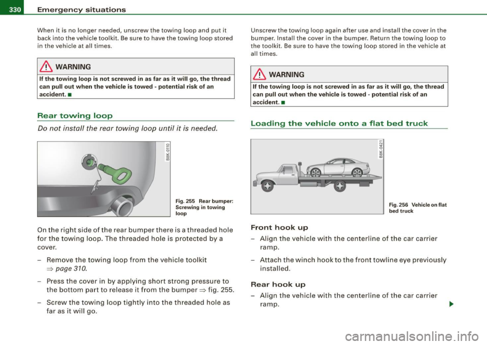
Fig. 255 Rear bumper :
Screwing in towing
loop
On the right side of the rear bumper there is a threaded hole
for the towing loop. The threaded hole is protected by a
cover.
- Remove the towing loop from the vehicle toolkit
=>
page 310.
- Press the cover in by applying short strong pressure to
the bottom part to release it from the bumper=> fig. 255.
Screw the towing loop tightly into the threaded hole as
far as it will go.
Unscrew the towing loop again after use and install the cover in the
bumper . Install the cover in the bumper. Return the towing loop to
the toolkit. Be sure to have the towing loop stored in the vehicle at
all times.
& WARNING
If the towing loop is not screwed in as far as it will go, the thread
can pull out when the vehicle is towed -potential risk of an
accident. •
Loading the vehicle onto a flat bed truck
Front hook up
Fig. 256 Vehicle on flat
bed truck
-Align the vehicle with the centerline of the car carrier
ramp.
- Attach the winch hook to the front towline eye previously
installed.
Rear hook up
- Align the vehicle with the centerline of the car carrier
ramp.
Page 333 of 360
![AUDI A5 COUPE 2010 Owners Manual Emergency situations -
----------------=-~----
- Attach the winch hook to the rear towline eye previously
installed.
[ i ] Tips
Check carefully to make sure the hook -up is secure bef AUDI A5 COUPE 2010 Owners Manual Emergency situations -
----------------=-~----
- Attach the winch hook to the rear towline eye previously
installed.
[ i ] Tips
Check carefully to make sure the hook -up is secure bef](/img/6/57582/w960_57582-332.png)
Emergency situations -
----------------=-~----
- Attach the winch hook to the rear towline eye previously
installed.
[ i ] Tips
Check carefully to make sure the hook -up is secure before moving
the car up the flatbed truck ramp. •
Lifting vehicle
Lifting with workshop hoist and with floor
jack
The vehicle may only be lifted at the lifting points illus
trated.
Fig . 257 Front lifting
point
- Read and heed WARNING~&.
Fig. 258 Rear lifting
point
- Locate li fting points ~ fig. 257 and ~ fig. 258.
- Adjust lifting arms of workshop hoist or floor jack to
match vehicle lifting points.
- Insert a rubber pad between the floor jack/workshop
hoist and the lifting points.
If you must lift your vehicle with a floor jack to work underneath , be
sure the vehicle is safely supported on stands intended for this
purpose .
Front lifting point
The lifting point is located on the floor pan reinforcement about at
the same level as the jack mounting point=> fig. 257.
Do not lift the
vehicle at the vertical sill reinforcement .
Rear lifting point
The lifting point is located on the vertical reinforcement of the lower
s ill for the onboard jack=> fig. 258.
Lifting vvith vehicle jack
Refer to => page 315 .
Vehicle care Do-it-yourself service irechnical data
Page 334 of 360

-Emergency situations PW:f..._--=---=----------------
& WARNING
• To reduce the risk of serious injury and vehicle damage .
- Always lift the vehicle only at the special workshop hoist and
floor jack lift points illustrated~ page
331, fig. 257 and
~ page 331, fig. 258.
- Failure to lift the vehicle at these points could cause the
vehicle to tilt or fall from a lift if there is a change in vehicle
weight distribution and balance. This might happen, for
example, when heavy components such as the engine block or
transmission are removed.
• When removing heavy components like these, anchor vehicle
to hoist or add corresponding weights to maintain the center of
gravity. Otherwise, the vehicle might tilt or slip off the hoist,
causing serious personal injury.
0 Note
• Be aware of the following points before lifting the vehicle:
- The vehicle should never be lifted or jacked up from under
neath the engine oil pan, the transmission housing, the front or
rear axle or the body side members . This could lead to serious
damage.
- To avoid damage to the underbody or chassis frame, a rubber
pad must be inserted between the floor jack and the lift points.
- Before driving over a workshop hoist, check that the vehicle
weight does not exceed the permissible lifting capacity of the hoist .
- Before driving over a workshop hoist, ensure that there is sufficient clearance between the hoist and low parts of the
vehicle. •
Page 335 of 360
Emergency situations Ill
-------------=--=----
• Do-it-yourself service
Page 336 of 360

ffl,__ __ G_e_ n_e_ ra_ l_i_n _f _o _ r_ m_ a_ t_io _ n __________________________________________________ _
General information
Explanation of technical data
Some of the technical data listed in this manual requires
further explanation.
The technical data for your vehicle is listed in the charts starting on
~ page 337. This section provides general information, notes and
restrictions which apply to this data. •
Vehicle identification
The key data is given on the vehicle identification number
(VIN) plate and the vehicle data sticker.
Fig. 259 Vehicle Identi
fication Number (VIN)
plate: location on
driver's side dash
panel Fig
. 260 The vehicle
identification label -
inside the luggage
compartment
The Vehicle Identification Number (VIN)
is located on the driver's side so that it is visible from the outside
through the windshield~ fig. 259.
The vehicle identification label
is located in the luggage compartment near the battery .
The label ~ fig. 260 shows the following vehicle data:
© Production control No.
0 Vehicle identification No.
© Type code number
© Type designation/engine output in Kilowatts
© Engine and transmission code letter
© Paint No./lnterior
0 Optional equipment No.'s
Vehicle data 2 to 7 are also found in your Warranty
& Maintenance
booklet .
The safety compliance sticker
is your assurance that your new vehicle complies with all applicable
Federal Motor Vehicle Safety Standards which were in effect at the
time the vehicle was manufactured. You can find this sticker on the ._
Page 337 of 360
General information -
----------------
left door jamb. It shows the month and year of production and the
vehicle identification number of your vehicle (perforation) as well as
the Gross Vehicle Weight Rating (GVWR) and the Gross Axle Weight
Rating (GAWR).
The high voltage warning label
is located on the lock carrier.
The spark ignition system complies with the Canadian
standard ICES-002. •
Applies to vehicles: with MMI
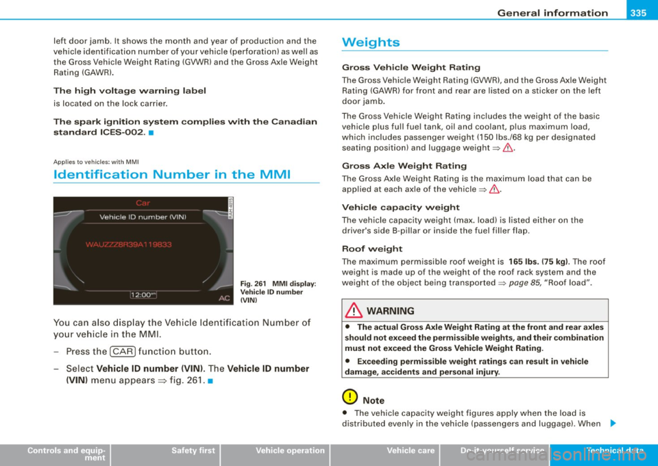
Identification Number in the MMI
Fig. 261 MMI display:
Vehicle ID number
(VIN)
You can also display the Vehicle Identification Number of
your vehicle in the MMI.
- Press the
I CAR) function button.
- Select
Vehicle ID number (VIN). The Vehicle ID number
(VIN)
menu appears =:> fig. 261. •
Controls and equip
ment Safety first Vehicle operation
Weights
Gross Vehicle Weight Rating
The Gross Vehicle
Weight Rating (GVWR), and the Gross Axle Weight
Rating (GAWR) for front and rear are listed on a sticker on the left
door jamb.
The Gross Vehicle Weight Rating includes the weight of the basic
vehicle plus full fuel tank, oil and coolant, plus maximum load,
which includes passenger weight (150 lbs./68 kg per designated
seating position) and luggage weight:::::,&.
Gross Axle Weight Rating
The Gross Axle Weight Rating is the maximum load that can be
applied at each axle of the vehicle:::::,.&,.
Vehicle capacity weight
The vehicle capacity weight (max. load) is listed either on the
driver's side B -pillar or inside the fuel filler flap.
Roof weight
The maximum permissible roof weight is 165 lbs. (75 kg). The roof
weight is made up of the weight of the roof rack system and the
weight of the object being transported:::::,
page 85, "Roof load".
& WARNING
• The actual Gross Axle Weight Rating at the front and rear axles
should not exceed the permissible weights, and their combination
must not exceed the Gross Vehicle Weight Rating.
• Exceeding permissible weight ratings can result in vehicle
damage, accidents and personal injury.
0 Note
• The vehicle capacity weight figures apply when the load is
distributed evenly in the vehicle (passengers and luggage) . When _,,
Vehicle care Do-it-yourself service Tec hn ica l da ta
Page 338 of 360
___ G_ e_n_ e_ r_ a _l _i_n _f _o _ r_ m_ a_ t_ i_ o _ n ________________________________________________ _
transporting a heavy load in the luggage compartment, carry the
load as near to the rear ax le as possible so that the vehic le's
handling is not impaired.
• Do not exceed the maximum perm issib le axle loads or the
maximum gross vehic le weight. Always remember that the vehic le's
handling wil l be affected by the extra load. Therefore , adjust your
speed according ly.
• Always o bserve local regulati ons .•
Dimensions
The s peci fica tions refer to t he basic mode l. Differences may occur
depending on the mode l type and options ordered, for examp le, tire
s izes .
0 Note
When driv ing up steep ramps, on rough roads, over curbs, etc . it is
important to remember that some parts of your vehicle, such as
spoilers or exhaust system components, may be c lose to the
ground . Be carefu l not to damage t hem. •
Page 339 of 360

___________________________________________________ D_a_ t_ a __ PII
Data
App lies to v ehicles : with 2.0 lite r 4-cy l. engine
211 hp, 2.0 liter 4-cyl. engine
En gin e data
Maximum output SAE net
Maximum torque SAE net
No _ of cylinders
Displacement
Stroke
Bore
Compression ratio
Fuel
Dim ension s (app rox.)
Length (with licence plate bracket)
Width (with outside mirrors fo lded)
Height (unloaded)
Turning circle diameter (curb to curb)
Ca pac ities (a pprox.)
F u el t ank
-Total capacity
- Reserve (of total capacity)
Wind shi eld and he adli ght * was her fluid container
E ngine oil
with filter change hp@rpm
lb-ft@ rpm
CID (cm
3
)
in (mm)
in (mm)
211 @ 4300 -6000
258
@ 1500 -4200
4
1 21 (1984)
3.65 (92.8)
3.25 (82.5)
9.6 : 1
Premium unleaded (91 AKI) Recommended for maximum engine performance. Fur
ther details =>
page 265, "Gasoline"
in (mm)
in (mm)
in (mm)
ft (ml
182.0 (4625)
73.0 (185 4)
54.0 (1372)
37 .4 (11.4)
gal Oiters)
gal (liters)
quarts (liters)
quarts (liters) 16.9 (64.0)
2.1 (8)
4 .8 (4_5)
4 .9 (4 .6)
•
Controls and equip
ment Safety first Vehicle operation
Vehicle care Do-it-yourself service Tec hn ica l da ta
Page 340 of 360
llftl __ D_a_ t_ a ___________________________________________________ _
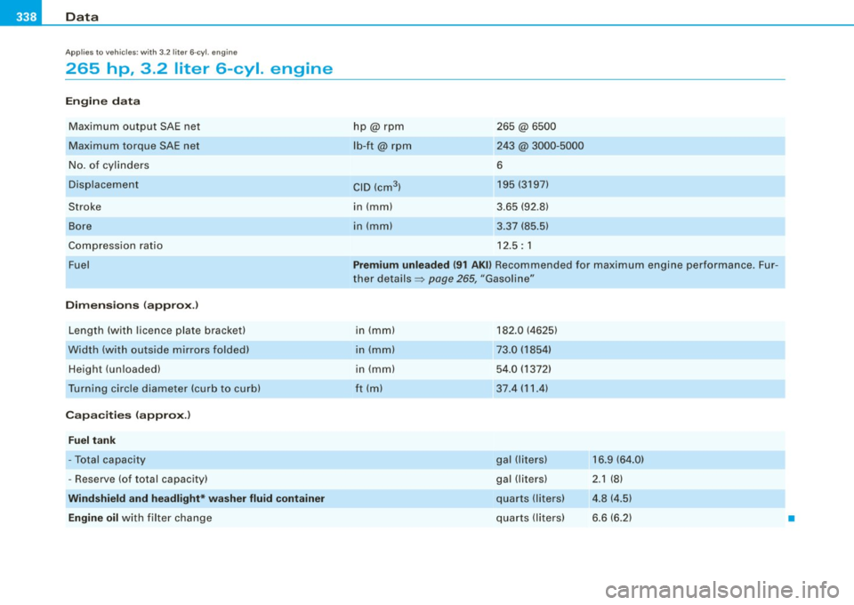
Applies to vehicles : wit h 3.2 li ter 6-c yl. en gine
265 hp , 3.2 liter 6-cyl. engine
Engine data
Max imum output SAE net
Maximum torque SAE net
No . of cy lin ders
Di spl ac eme nt
Stroke
Bo re
Comp ress ion rati o
Fuel
Dimensions (appro x.)
Lengt h (with licence plate brac ket)
Width (wit h ou ts ide mirrors folded)
Height (un loaded)
T urn ing c ircle diameter (curb to curb)
Capacities {approx .)
Fuel tank
-To tal capacity
- Rese rve (of total capacity)
Windshield and headlight* washer fluid container
Engine oil
with filter cha n ge h
p@ rpm
lb-ft@ rpm
CID (cm
3 )
in (mm)
in (m m) 265 @6500
243 @ 3000-5000
6 195 (3197)
3 .65 (92 .8)
3 .37 (85 .5)
1 2 .5: 1
Premium unleaded {91 AKll Recommended for maximum engine performance . Fur
t her deta ils =:>
pag e 265, "Gasoli ne"
i n (m m)
in (m m)
in (mm)
ft ( ml 1
82 .0 ( 4625)
73.0 (1854)
5 4 .0 ( 1372)
37 .4 (11.4 )
g al (l iters)
gal (li ters)
qua rts (liters)
q ua rts (l ite rs) 1
6.9 (64 .0)
2 .1 (8)
4. 8 ( 4.5)
6 .6 (6.2)
•