warning light AUDI A5 COUPE 2012 Owners Manual
[x] Cancel search | Manufacturer: AUDI, Model Year: 2012, Model line: A5 COUPE, Model: AUDI A5 COUPE 2012Pages: 316, PDF Size: 78.59 MB
Page 253 of 316

CD Note
Never use a fast charger as a booster to
start the engine. This will seriously dam
age sensitive electronic components, such
as control units, relays, radio, etc., as well
as the battery charger.
Battery replacement
The new battery must have the same specifi
cations and dimensions as the original equip
ment battery.
Intelligent energy management in your vehi
cle is responsible for distributing the electri
cal energy throughout your vehicle
c::, page 211. The intelligent energy manage
ment system w ill keep the engine battery
charged bette r then ve hicles w ithout this sys
tem. To ma ke sure t he addi tional e lectrical en
ergy is available once again after you have
changed the battery, we recommend that you
install batteries of the same type and man u
facture only (the same as those installed at
the time your vehicle was delivered). Specifi
cations are listed on the battery housing. Your
author ized Audi dealer must code the battery
i n the energy management system to enable
you to use the energy management functions
correctly after replac ing the bat tery .
If it is not possible to use a battery of this
type, the new battery must have the same ca pac ity, voltage (12 volts), amperage, con
s truction and pl ug seal ing .
When insta lli ng the battery, make sure the ig
ni tion and all e lectr ica l cons umers are turned
off.
(0 Note
Ma ke sure the venti lation hose on the s ide
of the battery is connected, othe rwis e
fumes or battery ac id can leak out.
@ For the sake of the environment
Because of the problem of proper d isposa l
of a batte ry, we recommend your author
ize d Au di dealer change th e batte ry for
Checkin g and fillin g 251
you. Batteries contain sul fur ic acid and
l ead and must always be disposed of prop
erly in comp liance with a ll environmental
regulations. Disposing of vehicle batter ies
i mproperly is very dange rous to the envi
r o nment .
Windshield/headlight*
washer container
Fig . 20 9 En gin e compa rtm ent : W inds hield an d head
light• washer fluid co ntai ne r
The was her fluid conta iner is mar ked w ith the
symbol Won its cap.
.., Before you check any thing in the engine
compa rtment,
alwa ys read and heed all
WARNINGS ~ .&_ in Working in the engine
compartment on page 23
7.
.., Lift the fi lle r ca p tongue to add washer flu
id. You can fi ll the containe r to t he top .
.., Press the cap back onto t he fi ller neck after
filling the container.
You can find the reservo ir
capacity in the table
in
c::> page 292.
Clean water should be used when filling up. If
poss ible, use soft wa ter to prevent scaling on
the washer jets . Always ad d a glass cleaner
solution (with frost protection in the winter) .
CD Note
Do not mix engine coola nt antifree ze o r
any other additives to fill up t he wind
sh ield washer reservoir .
Page 259 of 316
Tires an d wheel s 257
labe l and exact location on the vehicle wi ll
va ry slightly). inside the f
uel fi ller flap) always takes p rece
dence.
Note that the f ollowing tab le is accurate at
t he t ime o f go ing to press and is subject to
change. In the event of discrepancies, the tire
pressure label (On USA vehicles, the tire pres
sure label is located on the dr iver's side B-pil
lar. On Canada vehicles, the tire pre ssure labe l
is located either on the driver's side B-pillar or T
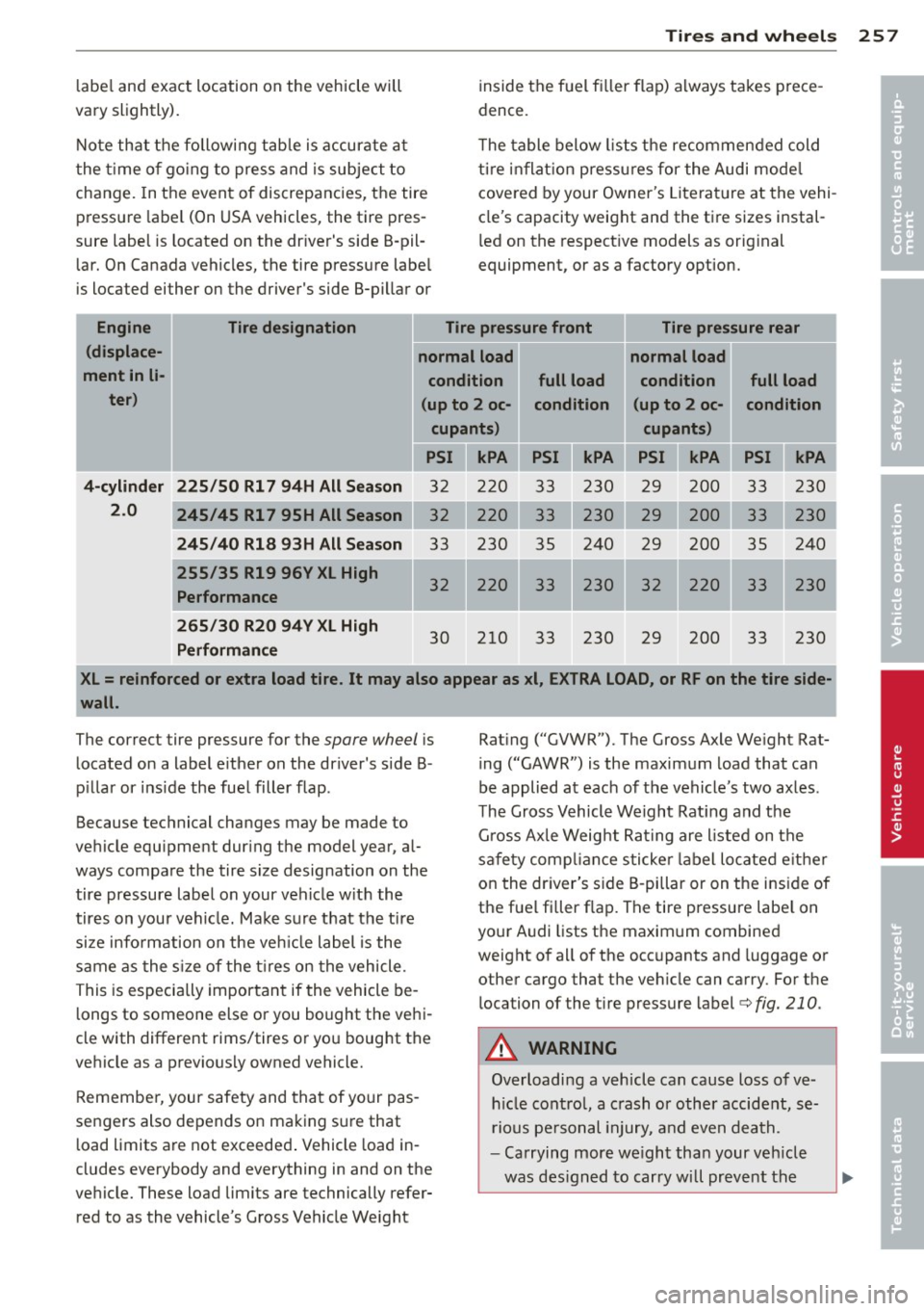
he table below lists the recommended cold
ti re in flat ion p ressu res for the Audi mode l
cove red by your Owner 's Literat ure at the vehi
cle's capacity weight and the t ire sizes instal
l ed on the respect ive models as orig inal
equipment, or as a factory option.
Engine Tire designation Tire pressure front Tire pressure rear
( displace-
normal load normal load
ment in li- condition full load condition
full load
ter) (up to 2 oc-condition (up to 2 oc- condition
cupant s) cupants)
PSI kPA PSI kPA PSI kPA
4-cylinder 225 /50 Rl 7 94H All Season
230
33 230
2
.0
245/45 Rl 7 95H All Season 230
245 /40 R18 93H All S eason 33 230 35 240 29 200 35 240
255 /35 R19 96V XL High 32 220 33 230 32 220 33 230 Performance
265 /30 R20 94V XL H igh
Perfo rmance
30 210 33 230 29 200 33 230
XL= reinforced or extra load tire. It may also appear as xl , EXTRA LOAD, or RF on the tire side
wall.
The correct tire pressure for the spare wheel i s
located on a label e ither on the driver's side B
p illar or ins ide the fuel filler flap .
Because technical changes may be made to
vehicle equ ipment dur ing the model year, a l
ways compare the tire s ize designation on the
tire pressure label on your vehicle w it h the
tires on your veh icle. Ma ke sure that the tire
size info rmation on the ve hicle label is the
s a me as the s ize of the t ires on the vehicle.
This is especia lly important if the vehicle be
l ongs to someone else or you bought the vehi
cle with different rims/tires o r you bought the
vehicle as a previously owned vehicle.
Remember, your safety and that of your pas
sengers also depends on mak ing su re that
l oad limits a re not exceeded . Vehicle load in
cludes everybody and everything in and on the
ve hicle. These load limits are technically refer
red to as the vehicle's G ross Vehicle We ight Rat
ing ("GVWR"). The Gross Axle We ight Rat
ing ("GAWR") is the maximum load that can
be applied at each of the vehicle's two axles .
T he Gross Vehicle Weight Rat ing and the
G ross Ax le Weig ht Rating are listed on the
sa fe ty comp liance sticke r label lo cated e ither
on the dr iver's s ide B-pillar or on the ins ide of
the fue l filler flap. The tire pressure labe l on
your A udi lists the maximum combined
weight of all of the occ upants and luggage or
other cargo that the veh icle can carry . For t he
loca tion of the t ire p ressure label¢
fig. 210.
A WARNING
Overloading a vehicle can cause loss of ve
h icle cont ro l, a c rash or other accide nt, se
rious pe rsonal injury, and even death.
- Ca rrying more we ight than your veh icle
was des igned to carry will prevent the
1
I
•
•
Page 273 of 316

wheels on your vehicle to ensure that the re
p lacement or a lternate tires and wheels allow
the TPMS to continue to function properly .
Tire pressure indicator appears
Appl ies to vehicles: w ith t ire pressure monitoring sys te m
The tire pressure indicator in the instrument
cluster informs you if the tire pressure is too
low or if there is a system malfunction.
Fig . 2 15 Display: underin flati on wa rning
Fig. 216 Disp lay: System malfunction
Using the ABS sensors, the tire pressure moni
tor ing system compares the t ire tread circum
fe rence and vibration characteristics of the in
d iv idual tires.
If t he pressure decreases in one
or mo re tires, th is is indica ted in the instru
men t clus ter with a
[I] warning symbo l and a
message ¢
fig. 215. The driver message in the
disp lay goes out after 5 seconds . The drive r
message can be d isplayed again by pressing
the
! SET ! button. If only one tire is affected,
the display will indicate its pos ition.
The tire press ure monitoring system must be
reset via radio o r MM! * each time the p res
sures are adjusted (e.g . when sw itching be
tween partial and full load pressure) or after
changing or replacing a t ire on your vehicle
<::> page 2 72 . You can find the recommended
Tires and wheels 2 71
tire p ressu res for your vehicle on the label on
drive r's side B-pillar
c!;> page 256 .
Tire tread circumference and vibrat ion charac
teris tics can change and cause a tire pressure
warning if:
- t he t ire p ress ure in one or mo re tires is too
low,
- t he tir e has s tructural damage,
- the t ire pressu re was changed, w heels rotat-
ed or rep laced but the TPMS was not reset
c::>page272 .
Warning symbols
[I] Loss of pressure in at least one tire c::> .&. .
Check the tire or tires and replace or repa ir if
necessary . T he
[I] indicator l ight in the instru
ment cluster also illum inates
<::> page 13.
Check/cor rect the p ress ures of all fou r tir es
and reset TPMS via radio o r M MI*.
11@1@1 (Ti re Pressure Monito ring System) Tire
pre ssure! Sy stem ma lfunction .
Ifll@lf:1 appears after switching the ignition
on or while driving
c::> fig . 216 and the [I] indi
cator light in the instr ument cluster blinks for
approximately one m inute and then stays on,
there is a system malfunction. See your au
thorized Aud i de aler as soon as possible .
& WARNING ~
- If the tire pressure ind icator appears in
the instrument cluster display, one or more of your tires is significant ly unde r
inflated. Reduce your speed immediately
and avoid any hard steering or b raking
maneuvers. Stop as soon as possib le and
check the tires and their pressures . In
flate the tire pressure to the prope r pres
sure as indica ted o n the v ehicl e's tire
p ressu re labe l
c::>page 256. Driving on a
sig nifican tly un der- infla te d tire causes
the t ire to ove rheat and can lead to ti re
fa ilu re . Unde r-inflation also is l ikely to
impair the vehicle's hand ling and stop
ping ability .
Page 275 of 316
What do I do now?
Vehicle tool kit
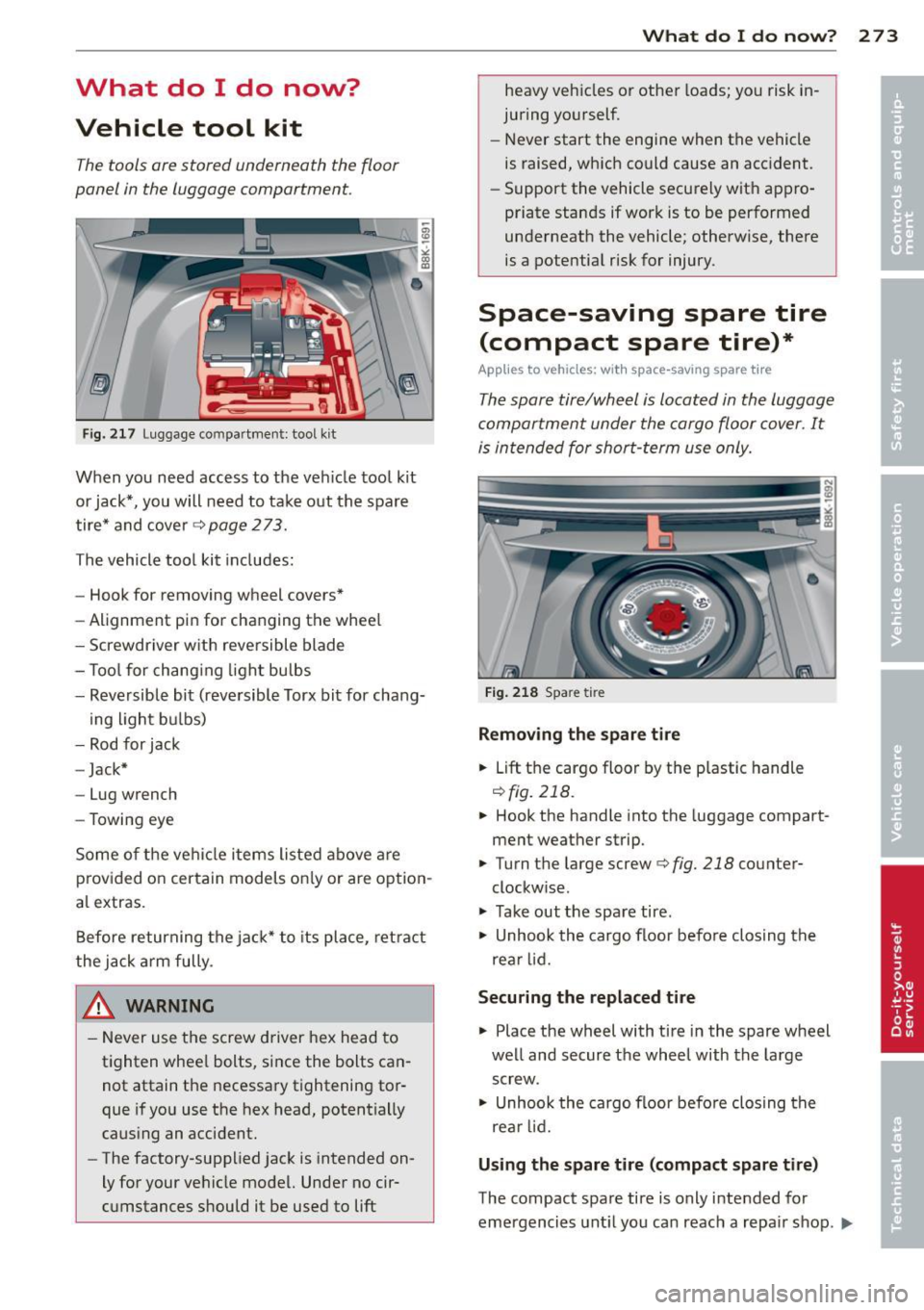
The tools ore stored underneath the floor
panel in the luggage comportment.
F ig . 2 17 Lug gage compar tment: tool kit
When you need access to the veh icle tool kit
or jack*, you will need to take o ut the spare
tire* and cover¢
page 2 73.
The vehicle tool kit includes:
- Hook for removing wheel covers*
- Alignment pin for changing the whee l
- Screwdriver w ith reversible blade
- T ool for chang ing light bulbs
- Reversible bit (reve rsible Torx bit for chang-
ing light b ulbs)
- Rod for jack
- Jack*
- Lug wrench
- Towing eye
Some o f the ve hicle items listed above are
p rov ided o n certain models on ly or are opt ion
a l extras.
Before returning the ja ck* to its place, ret ract
the jack a rm fully.
& WARNING
- Never use t he screw driver hex head to
tighten whee l bolts, since the bolts can
not attain the necessary tightening tor
que if yo u use the hex head, potentially
caus ing an accident.
- The factory-supplied jack is intended on
ly for your ve hicle model. Unde r no cir
c u mstances should it be used to
lift
What do I d o now ? 273
heavy ve hicles o r other loads; yo u risk in
juring yo urself.
- Never start the engi ne when the vehicle
is raised, which could cause an acc ident.
- Support the vehicle secu re ly wit h app ro
priate stands if wor k is to be performed
underneath the vehicle; otherwise, there
is a pote ntia l risk for injury .
Space-saving spare tire
(compact spare tire)*
App lies to vehicles: wit h space-saving spare tire
The spore tire/wheel is located in the luggage
comportment under the cargo floor cover. It
is in tended for short -term use only.
Fi g. 2 18 Spa re tire
Removing the spare ti re
.. Lift
th e cargo floo r by the p lastic handle
r:!) fig. 218.
.. Hook the handle into the luggage compart
ment weather strip.
.. Turn t he large screw¢
fig. 218 counter
clockw ise .
.. Take out the spare tire .
.. Unhook the cargo floor befo re clos ing the
re ar l id.
Securing the repl aced tire
.. Place the wheel with tire in the spare wheel
we ll and secure the wheel with the large
screw.
.. Unhook the cargo floor befo re closing t he
re ar lid .
Using the spare tire (compact spare tire)
The compact spa re tire is only i ntended for
emergencies unt il you ca n reach a repa ir shop .
l)JI,
Page 277 of 316
A WARNING ,~ -
You or your passengers could be injured
while changing a wheel if you do not fol
low these safety precautions:
- If you have a flat tire, move a safe dis
tance off the road. Turn off the engine,
turn the emergency flashers on and use
other warning devices to alert other mo
torists.
- Make sure that passengers wait in a safe
place away from the vehicle and well
away from the road and traffic.
- To help prevent the vehicle from moving
suddenly and possibly slipping off the
jack, always fully set the parking brake
and block the wheel diagonally opposite
the wheel being changed with the fold
ing chocks or other objects. When one
front wheel is lifted off the ground, plac
ing the Automatic Transmission in "P"
(Park) will
not prevent the vehicle from
moving .
- Before you change a wheel, be sure the
ground is level and firm. If necessary,
use a sturdy board under the jack.
- After installing the inflatable spare tire,
make sure that you replace the flat tire/
wheel in its storage area properly and
tighten the knurled retaining screw se
curely.
0 Note
If you are changing the wheel on a steep
incline, use a rock or similar object to
block the opposite wheel to prevent the
vehicle from moving.
(D Tips
Obey all laws.
Changing a wheel
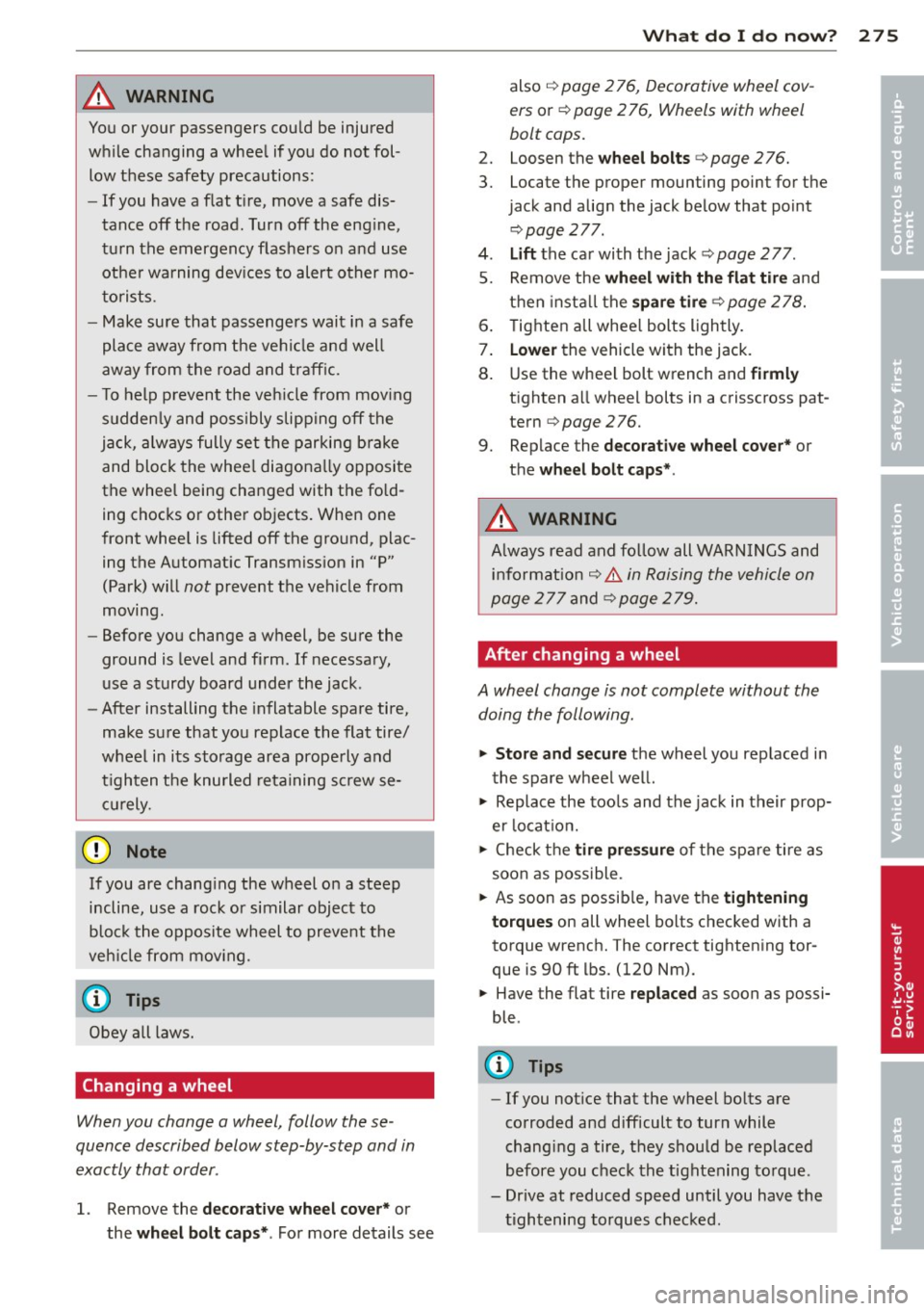
When you change a wheel, follow these
quence described below step-by-step and in
exactly that order .
1. Remove the decorative wheel cover* or
the
wheel bolt caps* . For more details see
What do I do now? 275
also ~ page 2 76, Decorative wheel cov
ers
or ¢ page 2 76, Wheels with wheel
bolt caps.
2. Loosen the wheel bolts ¢ page 276.
3. Locate the proper mounting point for the
jack and align the jack below that point
¢page 277 .
4.
Lift the car with the jack ¢ page 2 77.
5. Remove the
wheel with the flat tire and
then install the
spare tire ¢page 278.
6. Tighten all wheel bolts lightly.
7.
Lower the vehicle with the jack.
8. Use the wheel bolt wrench and
firmly
tighten all wheel bolts in a crisscross pat
tern ¢
page 2 76.
9. Replace the
decorative wheel cover* or
the
wheel bolt caps* .
A WARNING
Always read and follow all WARNINGS and
information ~.&.
in Raising the vehicle on
page
277 and ¢page 279.
After changing a wheel
A wheel change is not complete without the
doing the following.
"' Store and secure the wheel you replaced in
the spare wheel well.
"' Replace the tools and the jack in their prop
er location.
"' Check the
tire pressure of the spare tire as
soon as possible.
"' As soon as possible, have the
tightening
torques
on all wheel bolts checked with a
torque wrench. The correct tightening tor
que is 90 ft lbs. (120 Nm).
"' Have the flat tire
replaced as soon as possi
ble.
(D Tips
- If you notice that the wheel bolts are
corroded and difficult to turn while
changing a tire, they should be replaced
before you check the tightening torque .
- Drive at reduced speed until you have the
tightening torques checked. •
•
Page 279 of 316
@ Tips
-Never use the hexagonal socket in the
handle of the screwdriver to loosen or
tighten the wheel bolts.
- If a whee l bolt is very tight, you may find
it easier to loosen by carefully pushing
down on the end of the wheel bolt
wrench with
one foot only. As you do so,
hold on to the car to keep your balance
and take ca re not to slip.
Raising the vehicle
The vehicle must be li~ed with the jack first
before the wheel can be removed .
*
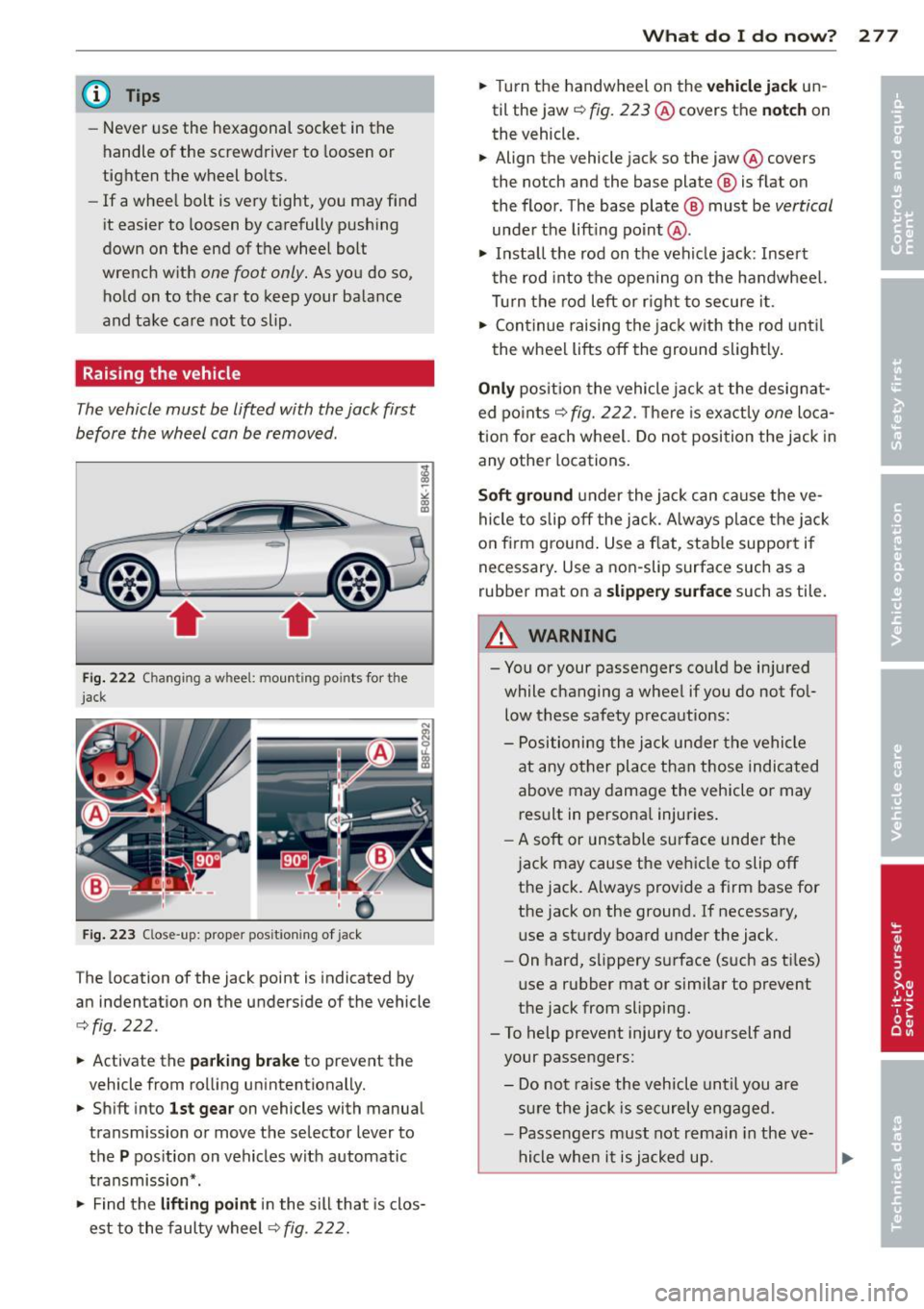
Fig. 2 22 Changing a whee l: moun ting po ints for the
jack
F ig . 223 C lose -up: proper positioning of jack
The location of the jack point is indicated by
an indentation on the underside of the vehicle
¢ fig. 222 .
.. Activate the parking b rake to prevent the
vehicle from rolling unintentionally.
.. Shi ft into
1st gea r on vehicles with manual
transmission or move the selector lever to
the
P pos ition on vehicles with automatic
t ransmission* .
.,. Find the
liftin g point in the sill that is clos
est to the faulty wheel~
fig. 222.
What do I d o now ? 277
.. Turn the handwheel on the ve hicl e jac k un
til the jaw
c::, fig. 223@covers the not ch on
the vehicle.
.. Align the vehicle jack so the jaw @covers
the notch and the base plate ® is flat on
the floor. The base plate
@ must be vertical
under the lift ing po int @ .
.,. Insta ll the rod on the vehicle jack: Inse rt
the rod into the opening on the handwheel.
Turn the rod left or r ight to secure i t.
.. Continue raising the jac k w ith the rod unti l
the wheel lifts off the ground slightly.
O nly pos ition the vehicle jack at the designat
ed po ints
c::, fig. 222. T here is exactly one loca
tion for each wheel. Do not position the jack in
any other locations .
Soft ground under the jack can cause the ve
hicle to slip off the jack. A lways place the jack
on f irm ground . Use a flat, stab le support if
necessary. Use a non-slip surface such as a
rubber mat on a
s lippery surface such as tile.
A WARNING
- You or your passengers cou ld be in jured
while changing a wheel if you do not fol
low these safety precautions:
- Positioning the jack un der the vehicle
at any other place than those indicated
above may damage the vehicle or may result in persona l injuries .
- A soft or unstable surf ace under the
jac k may cause the veh icle to slip off
the jack. Always prov ide a f irm base for
the jack on the ground. If necessary,
use a sturdy board under the jack.
- On hard, slippery surface (such as ti les)
use a rubber mat or similar to prevent
the jack from slipping.
- To help prevent injury to yourself and
your passengers:
- Do not ra ise the vehicle until you are
s u re the jack is securely engaged .
- Passengers must not remain in the ve
h icle when it is ja cked up.
Page 282 of 316
280 Fuses and bulbs
Fuses and bulbs
Fuses
Replacing a fuse
Fuses that have blown will have metal strips
that have burned through.
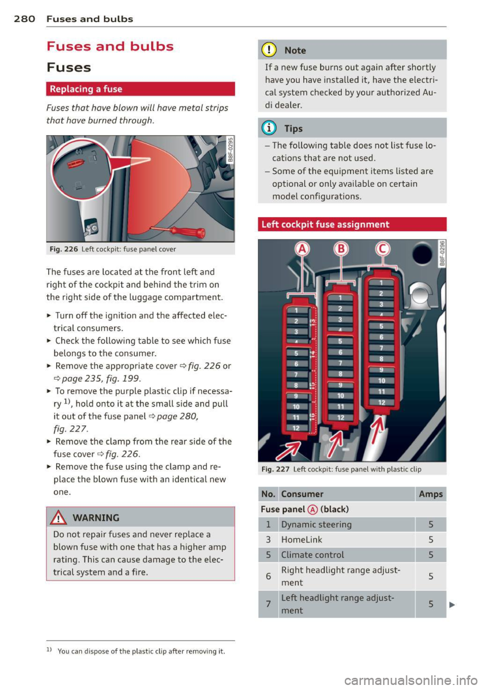
Fig. 226 Left cockpit: fuse panel cover
The fuses are located at the front left and
right of the cockpit and behind the trim on
the right side of the luggage compartment.
• Turn off the ignit ion and the affected elec
trical consumers.
• Check the following table to see which fuse
belongs to the consumer.
• Remov e the appropriate cover¢
fig. 226 or
¢ page 235, fig. 199.
• To remove the purple plastic cl ip if necessa
ry
1l, hold onto it at the small side and pull
it out of the fuse panel
c:> page 280,
fig. 227.
• Remove the clamp from the rear side of the
fuse cover ¢
fig. 226.
• Remove the fuse using the clamp and re
place the blown fuse w ith an ident ical new
one.
A WARNING
Do not repair fuses and never replace a
blown fuse with one that has a higher amp
rating. This can cause damage to the elec
trical system and a fire.
ll You ca n dispose of the p lastic clip afte r remov ing it.
(D Note
If a new fuse burns out again after shortly
have you have installed it, have the electri
cal system checked by your authorized Au
d i dealer .
(D Tips
-The following table does not list fuse lo
cations that are not used.
- Some of the equipment items listed are
optional or only available on certain
model configurations.
Left cockpit fuse assignment
Fig . 227 Left cockpi t: fu se pane l with plastic clip
No. Consumer
Fuse panel @(black)
1 Dynamic steering
3 Homelink
5
6
Climate control Right headlight range adjust
ment
Amps
5
5
5
5
7
Left headlight range adjust
ment
5 ...
•
Page 285 of 316
Bulbs
Replacing bulbs
For your safety, we recommend that you have
your authorized Audi dealer replace any bulbs
for you .
It is becoming increasingly more and more
difficult to replace vehicle light bulbs since in
many cases, other parts of the car must first
be removed before you are able to get to the
bu lb . T his appl ies especially to the light bu lbs
in the front of your car which you can on ly
reach through the engine compartment .
Sheet metal and bulb ho lders can have sharp
edges that can cause ser ious cuts, parts must
be correctly taken apart and then p roperly put
back together to help prevent breakage of
parts and long term damage from water that
can enter housings that have not been proper
l y resealed.
F or your safety, we recommend that you have
your authorized Audi dealer replace any bulbs
for you, since your dealer has the proper tools,
the correct bu lbs and the expertise.
G as disch arge la mp s (Xe no n li ght s)*:
Due to the high electrical vo ltage, have the
bu lbs rep laced by a qualified technician.
H eadlights with Xenon l ight a re identified by
the high voltage sticker.
& WARNING
Changing Xenon lamps without the neces
sary equipment can cause serious personal
injury.
- Bul bs are pressurized and can exp lode
when being changed . Potential risk of in
jury!
- On vehicles equipped with gas discharge
bulbs (Xenon light) * life-threatening in
jur ies can result from improper handling
of the high-voltage portions of such
lamps!
- Only your authorized Aud i dea ler or a
qualified workshop should change the
bulbs in gas discharge lamps. There a re
Fu ses and bulb s 28 3
parts with sharp edges on the open ings
and on the bulb holders that can cause
serious cuts. If you are uncertain about
what to do, have the work performed by
an author ized Audi dealer or other quali
fied workshop . Ser ious personal injury
may result from improperly perfo rmed
wo rk.
(j) Tips
- If you still prefer to replace the light
bulbs yourself , be aware that the engine
compartment is a hazardous area to
work in
c::> page 230, Engine compart
ment
o=:> ,& .
-It is best to ask your authorized Audi
dealer whenever yo u want to change a
bulb .
•
•
Page 286 of 316

284 Emergency situations
Emergency situations
General
This chapter is intended for trained emer
gency crews and working personnel who
have the necessary tools and equipment to perform these operations.
Starting by pushing or
towing
Q;) Note
Vehicles with an automatic transmission
cannot be started by pushing or towing.
Starting with jumper
cables
If necessary , the engine can be started by
connecting it to the battery of another vehi
cle.
If the engine should fail to start because of a
discharged or weak battery, the battery can be
connected to the battery of
another vehicle,
using a
pair of jumper cables to start the en
gine .
Jumper cables
Use only jumper cables of sufficiently
large cross section to carry the starter current
safely. Refer to the manufacturer's specifica
ti ons.
Use only jumper cables with
insulated termi
nal clamps which are distinctly marked :
plus(+) cable in most cases colored red
minus (-) cable
in most cases colored black .
A WARNING
Batteries contain electricity, acid, and gas.
Any of these can cause very serious or fatal
injury. Follow the instructions below for
safe handling of your vehicle's battery.
- Always shield your eyes and avoid lean
ing over the battery whenever possible. -
A discharged battery can freeze at tem
peratures just below
32 °F (0 °(). Before
connecting a jumper cable, you must
thaw the frozen battery completely, oth
erwise it could explode.
- Do not allow battery acid to contact eyes
or skin . Flush any contacted area with
water immediately .
- Improper use of a booster battery to
start a vehicle may cause an explosion.
- Vehicle batteries generate explosive gas
es . Keep sparks, flame and lighted ciga
rettes away from batteries .
- Do not try to jump start any vehicle with
a low acid level in the battery .
- The voltage of the booster battery must
also have a 12-Volt rating. The capacity
(Ah) of the booster battery should not be
lower than that of the discharged bat
tery . Use of batteries of different voltage
or substantially different "Ah" rating
may cause an explosion and personal in
jury.
- Never charge a frozen battery. Gas trap
ped in the ice may cause an explosion.
- Never charge or use a battery that has
been frozen. The battery case may have
be weakened.
- Use of batteries of different voltage or
substantially different capacity (Ah) rat
ing may cause an explosion and injury.
The capacity (Ah) of the booster battery
should not be lower than that of the dis
charged battery.
- Before you check anything in the engine
compartment, always read and heed all
WARNINGS¢
page 230, Engine com
partment.
@ Note
- Applying a higher voltage booster bat
tery will cause expensive damage to sen
sitive electronic components, such as
control units, relays, radio, etc.
- There must be no electrical contact be
tween the vehicles as otherwise current
could already start to flow as soon as the
positive(+) terminals are connected. ..,.
Page 287 of 316
@ Tips
-The discharged battery must be properly
connected to the vehicle's electrical sys
tem. When jump start ing or charging the
battery, never connect the negative
ground cable to the battery negative
post because the battery manager sys
tem must be able to detect the battery's
state of cha rge . A lways connect the neg
ative g round cab le to the negative
gro und post o f the battery manage r con
trol uni t.
Use of jumper cables
Make sure to connect the jumper cobl e
clomps in exactly the order describ ed b elow!
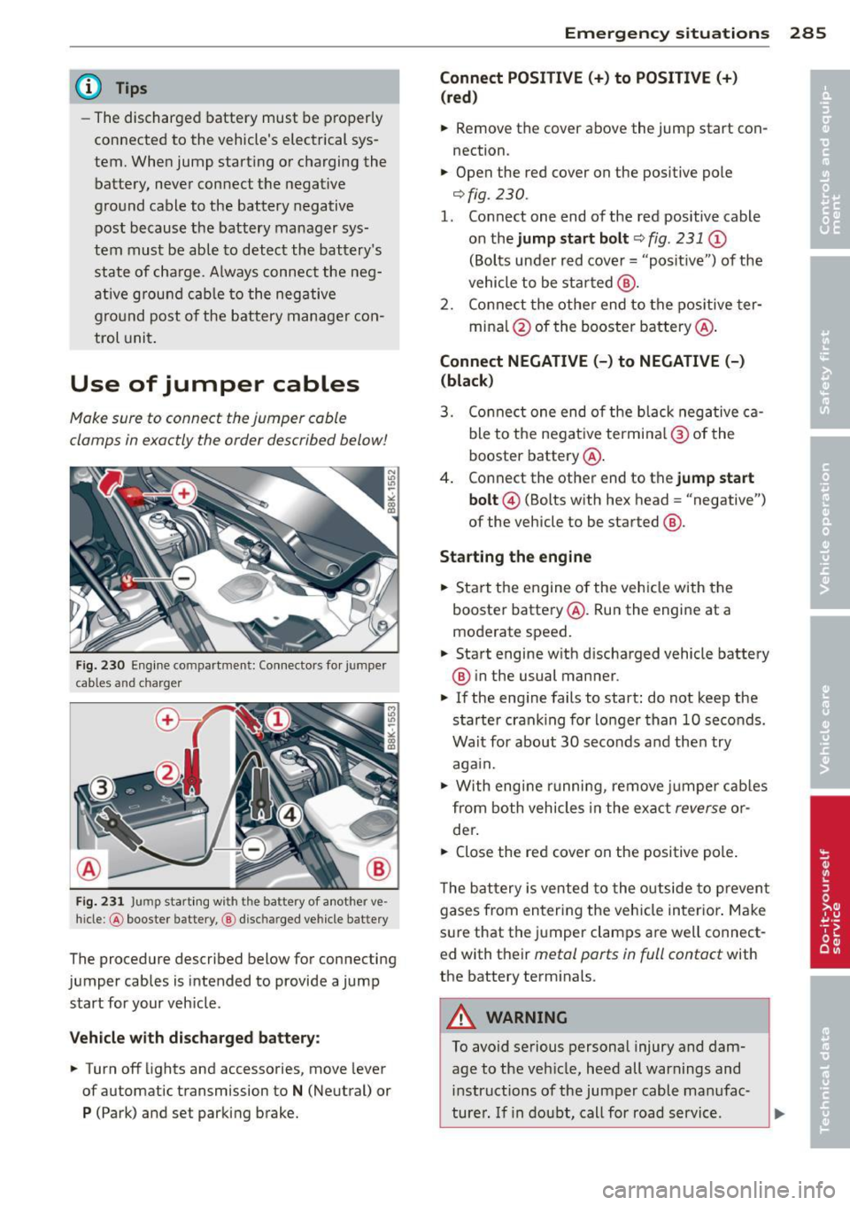
Fig. 230 Engine co mpartmen t: Con ne ctors fo r jum per
c ables a nd char ger
Fi g. 231 Jump s tart in g w ith t he ba ttery of a not her ve
hi cle :@ booster battery, @ disc harged vehicle bat tery
The procedure described below for connecting
jumper cables is intended to provide a jump
start for your veh icle .
Vehicle with discharged batter y:
.. Turn off lights and accessories , move lever
of automatic transmission to
N (Neutral) or
P (Park) and set parking brake.
Emergenc y situ ation s 285
Connect POSI TIVE(+ ) to POSITIVE (+ )
(red )
.. Remove the cover above the jump start con
nection .
.. Open the red cover on the positive pole
¢fig. 230 .
1. Connect one end of the red positive cable
on the
jump sta rt bolt ¢ fig. 231 (D
(Bolts under red cover= "positive ") of the
vehicle to be star ted @.
2. Connect the othe r end to the pos itive ter -
mina l@ of the booster battery @.
Connect NEGATIVE (-) to NEGATIVE (-)
(black )
3. Connect one end of the b lack negative ca
ble to the nega tive te rmi na l@ of the
booster battery @.
4 . Connect the other end to the
jump start
bolt @
(Bolts with hex head = "negative")
of the vehicle to be started @.
Sta rting the engine
.. Start t he engine of the veh icle w ith the
booster battery @. Run the engine at a
moderate speed .
.. Start engine w ith d ischarged vehicle battery
® in the usual manner .
.. If the eng ine fails to start: do not keep the
starter crank ing for lo nger than 10 seconds .
Wait for about 30 seconds and the n try
aga in .
.,. With engi ne runni ng , remove j umper cab les
from both vehicles in the exact
reverse o r
der .
.. Close the red cover on the positive pole .
T he battery is vented to the o utside to p revent
gases from entering the veh icle in ter ior . Make
s ur e that the j umper clamps a re well connect
e d with their
metal ports in full contact with
the batte ry terminals.
A WARNING
To avoid serious personal injury and dam
age to the vehicle, heed all warnings and
instructions of the jumper cable manufac-
turer . If i n doubt, call for road service .
Ill>