AUDI A5 COUPE 2018 Owners Manual
Manufacturer: AUDI, Model Year: 2018, Model line: A5 COUPE, Model: AUDI A5 COUPE 2018Pages: 409, PDF Size: 67.63 MB
Page 371 of 409
Emergency assistance
Repairing tires
Applies to: vehicles w ith tire mob ility k it
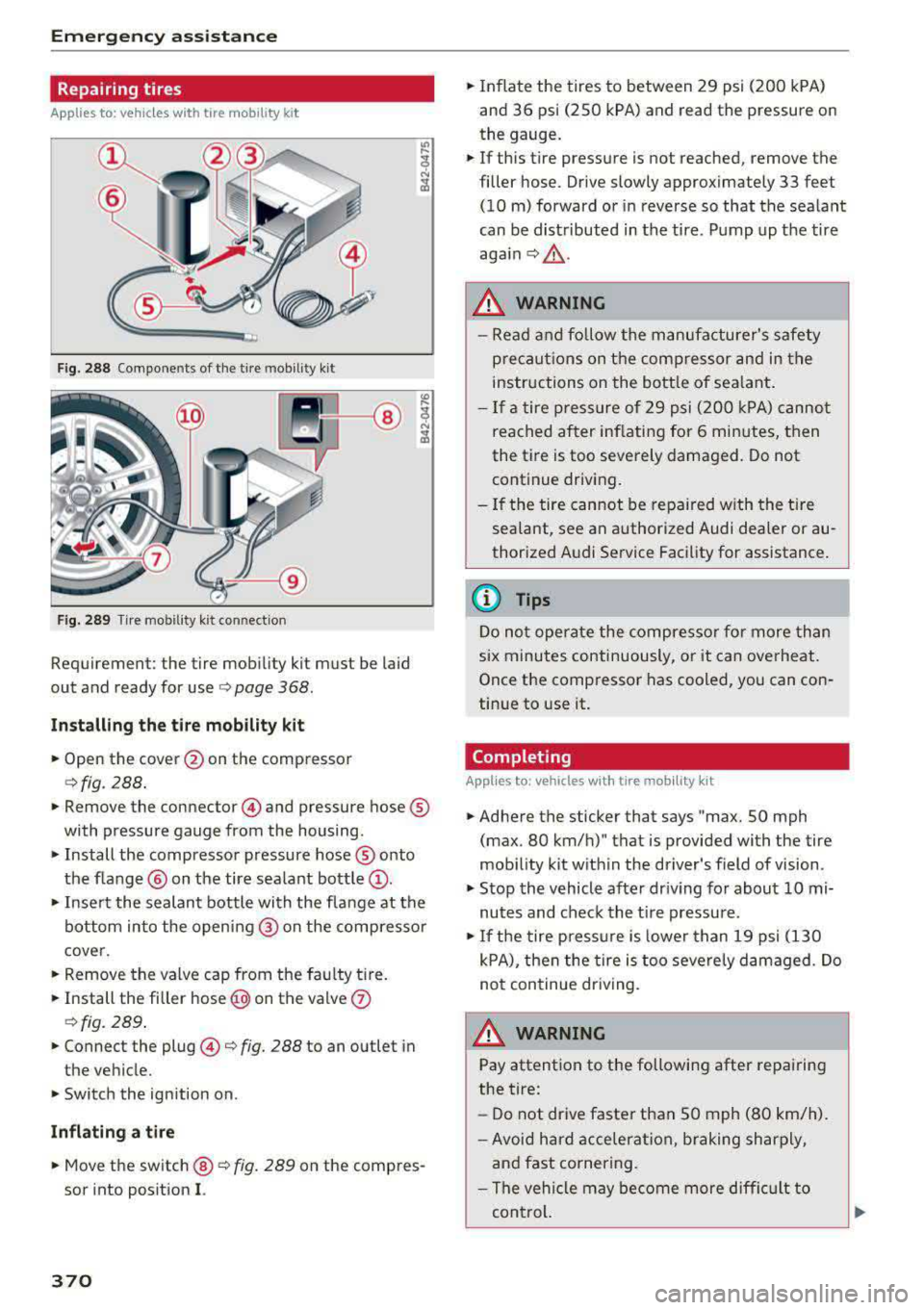
Fig. 288 Components of the tire mobility kit
F ig. 289 Tire mobility k it connec tion
Requirement: the tire mobility kit must be laid
out and ready for use
o page 368.
Installing the tire mobility kit
.. Open the cover @on the compressor
¢fig. 288 .
.. Remove the connector @) and pressure hose®
with pressure gauge from the housing.
• Install the compressor pressure hose ® onto
the f lange @ on the tire sea lant bottle
(D .
.. Insert the sealant bottle with the flange at the
bottom into the opening @ on the compresso r
cover.
.. Remove the valve cap from the fau lty tire.
.. Install the filler hose @) on the valve (J)
ofig. 289 .
.. Connect the plug@¢ fig. 288 to an outlet in
the vehicle.
.. Switch the ignition on.
Inflating a tire
.. Move the switch @ o fig. 289 on the compres
sor into position
I.
370
.. Inflate the tires to between 29 psi ( 200 kPA)
and 36 psi (250 kPA) and read the pressur e on
the gauge .
.. If this tire pressure is not reached, remove the
filler hose. Drive slowly approximately 33 feet
(10 m) forward or in reverse so that the sea lant
can be distributed in the tire. Pump up the tire
aga in¢ ,&.
.
.&_ WARNING
-Read and follow the manufacturer's safety
precaut ions on the compressor and in the
instructions on the bottle of sea lant .
- If a tire pressure of 29 psi (200 kPA) cannot
reached after inflating for 6 minutes, then
the tire is too severely damaged. Do not
continue driving.
- If the tire cannot be repa ired with the tire
sealant, see an authorized Audi dealer or au
thorized Audi Service Facility for assistance.
(D Tips
Do not operate the compressor for more than
six minutes continuously, or it can overheat.
Once the compressor has cooled, you can con
tinue to use it.
Completing
App lies to : vehicles wit h tire mob ility kit
.. Adhere the sticker that says "max. SO mph
(max . 80 km/h)" that is provided with the tire
mob ility kit with in the driver's field of vision.
.. Stop the vehicle after driv ing for about 10 mi
nutes and check the tir e pressure.
.. If the tire press ure is lower than 19 psi (130
kPA), then the tire is too severely damaged. Do
not continue driving .
.&_ WARNING
Pay attention to the following after repairing
the tire:
- Do not drive faster than SO mph (80 km/h).
- Avoid hard acceleration, braking sharply,
and fast cornering .
- The vehicle may become more difficult to
con trol.
Page 372 of 409
-If the t ire is too severely damaged , see an
authorized Aud i dealer or authorized Aud i
Service Facility for assistance .
@ For the sake of the environment
You can give the used tire sealant bottle to an
author ized Audi dealer or authorized A udi
Serv ice Facility for disposal.
@ Tips
Remember to obtain a new bottle of sea lant
from an authorized Audi dea ler or authorized
Audi Service Facility after repair ing a tire.
Replacing a wheel
Preparation
You must complete the preparation before
changing a tire .
.,. Read and follow the important safety precau
tions ~ page 368 .
.,. Set the parking brake .
Applies to: ve hicles with man ua l transmiss ion
.,. Shift in to 1st gear.
Applies to: ve hicles with automat ic t ra n smi ssio ns
.,. Select the P selector leve r pos ition .
.,. When towing a trailer: disconnect the tra iler
from your veh icle .
.,. Lay out the veh icle tool kit 9 page 368 and the
spare tire
~ page 375 .
.,. Switch the ignition off .
A WARNING
When using the vehicle jack* on a road with a
steep hill or offroad, you must take extra pre
cautions to prevent the vehicle from rolling .
Use suitab le objects to b lock the front and
back of the wheel that is diagonal from the
wheel with the flat tire.
A WARNING
You or your passengers could be in ju red wh ile
chang ing a wheel if you do not follow these
safety precautions :
Emergen cy a ssis tanc e
-If you have a flat tire, move a safe distance
off the road. Turn off the eng ine, turn the
emergency flashers on and use other warn
ing dev ices to alert other motorists .
- Make sure that passengers wait in a safe
place away from the vehicle and well away
from the road and traff ic .
- To help prevent the veh icle from moving
suddenly a nd possib ly slipping off the jack*,
always fully set the park ing brake and block
the front and back of the wheel diagonally opposite the wheel being changed. When
one front wheel is lif ted off the gro und,
p la cing the Automa tic Transmission in P
(Park) will
not prevent the vehicle from
moving.
- Before you change a wheel, be sure the
g ro und is leve l and firm. If necessary, use a
sturdy board under the jack *.
- Always store the vehicle tool kit, the jack *
a nd the replaced tire in the luggage com
partment
~ page 263 .
(D Tips
Obey all laws .
Removing the caps
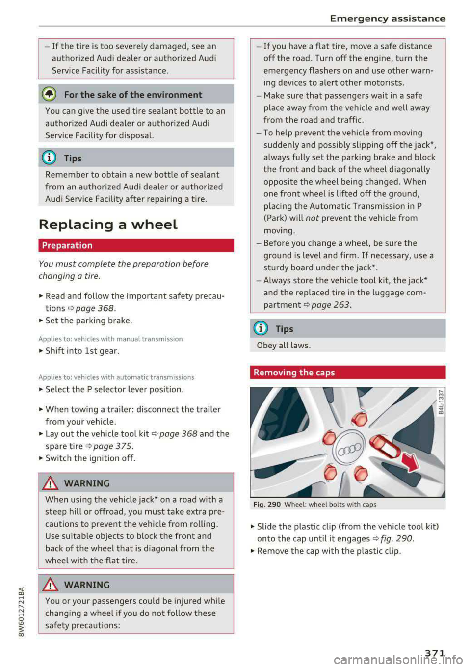
Fig. 290 W hee l: whee l bolt s w ith ca ps
.,. Slide the p lastic clip (from the veh icle tool k it)
on to the cap unt il it
engages ~ fig. 290.
.,. Remove the cap with the p lastic clip.
371
Page 373 of 409
Emergency assistance
Loosening the wheel bolts
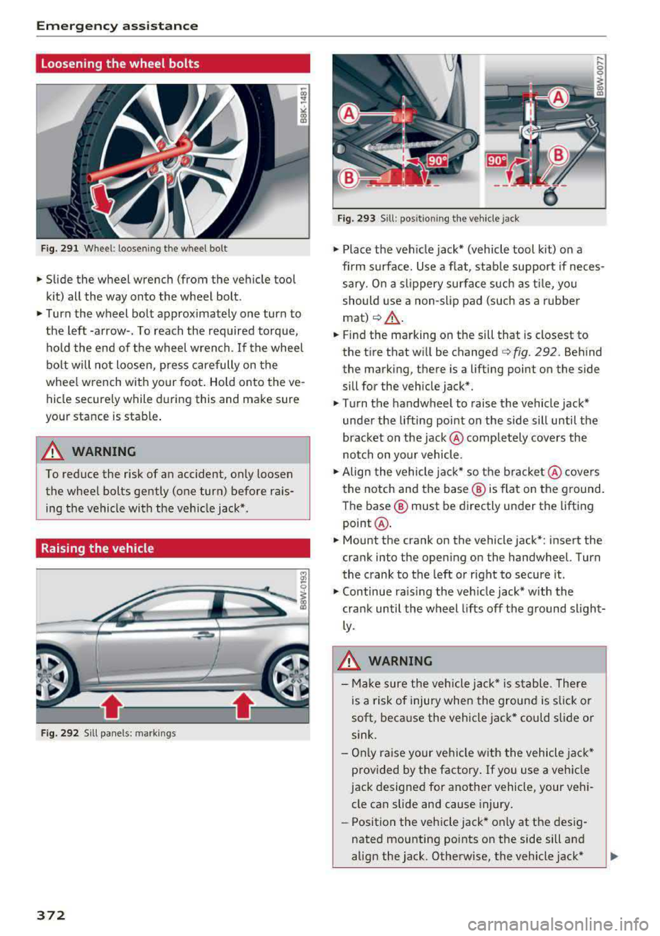
Fig. 291 Wheel: loosening the wheel bolt
• Slide the wheel wrench (from the vehicle tool
kit) all the way onto the wheel bolt.
• Turn the wheel bolt approximately one turn to
the left -arrow-. To reach the required torque,
hold the end of the wheel wrench. If the wheel
bolt will not loosen, press carefully on the
whee l wrench with your foot. Hold onto the ve
hicle securely while during this and make sure
your stance is stable .
A WARNING
To reduce the risk of an accident, only loosen
the wheel bolts gently (one turn) before rais
ing the vehicle with the veh icle jack*.
Raising the vehicle
Fig . 292 Sill panels: markings
372
Fig. 293 Sill: positio ning the vehicle jack
• Place the veh icle jack* (vehicle tool kit) on a
firm s urface. Use a flat, stable support if neces
sary. On a slippery surface such as tile, you
should use a non-slip pad (such as a rubber
mat)¢ &.
• Find the marking on the sill that is closest to
the tire that will be changed
¢fig. 292. Behind
the marking, there is a lifting point on the side
sill for the vehicle jack*.
• Turn the handwheel to raise the vehicle jack*
under the lifting point on the side sill until the
bracket on the jack @ completely covers the
notch on your vehicle.
• Align the vehicle jack* so the bracket @covers
the notch and the base ® is flat on the ground.
The base ® must be directly under the lifting
point @.
• Mount the crank on the vehicle jac k*: insert the
crank into the opening on the handwheel. Turn
the crank to the left or right to secure it.
• Continue ra is in g the veh icle jack* with the
crank until the wheel lifts off the ground slight
ly.
A WARNING
- Ma ke sure the vehicle jack* is stable. Th ere
is a risk of injury when the ground is slick or
soft, because the vehicle jack* could slide or
sink.
- Only raise your vehicle with the vehicle jack*
provided by the factory . If you use a vehicle
jack designed for another vehicle, your vehi
cle can slide and cause injury.
- Position the vehicle jack* only at the desig
nated mounting points on the side sill and
align the jack. Otherwise, the vehicle jack*
Page 374 of 409
could slip and cause an injury if it does not
have sufficient hold on the vehicle.
- To reduce the risk of an accident, never start
the engine when the vehicle is raised.
- To reduce the risk of injury, support the ve
hicle securely with suitable stands if work is
to be performed underneath the vehicle.
- To help prevent injury to yourself and your
passengers:
- Do not raise the vehicle until you are sure the jack* is securely engaged.
- Passengers must not remain in the vehicle when it is jacked up.
- Make sure that passengers wait in a safe
place away from the vehicle and well away
from the road and traffic.
- Make sure jack position is correct, adjust as necessary and then continue to raise
the jack*.
- If work has to be done under the vehicle, ensure that it is safely supported on suita
ble stands
-risk of injury!
- Never start the engine when the vehicle is on the jack*
-risk of accident!
(D Note
Do not lift the vehicle by the sill. Position the
vehicle jack* only at the designated mounting points on the side sill. Otherwise, your vehicle
will be damaged.
Removing and installing a wheel
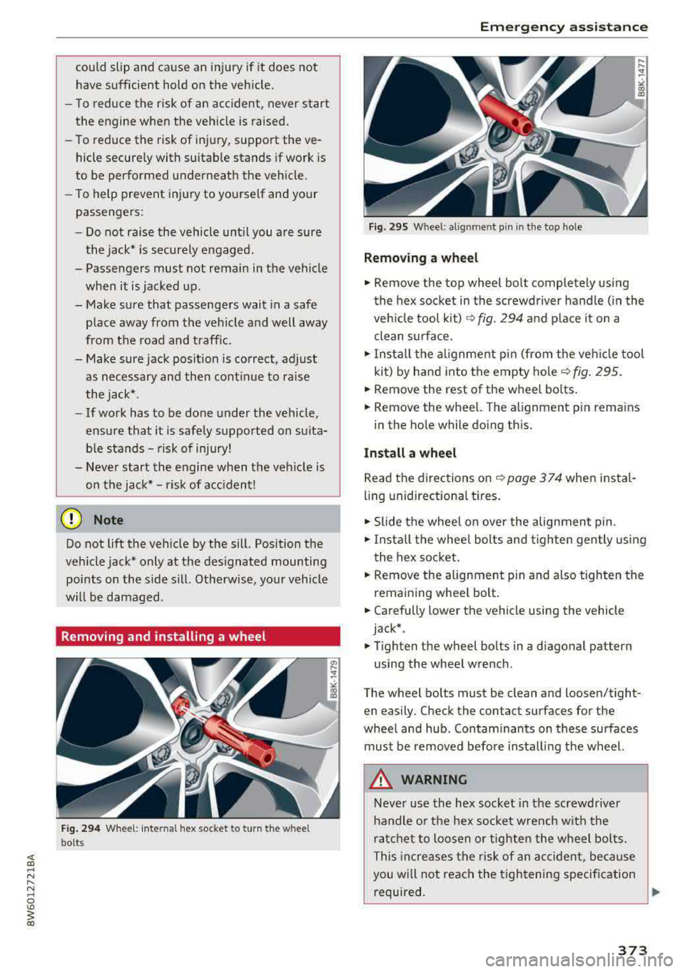
Fig. 294 Wheel: inte rnal hex socket to turn the whee l
bolts
Emergency assistance
Fig. 295 Whee l: alignment pin in the top ho le
Removing a wheel
.,. Remove the top wheel bolt completely using
the hex socket in the screwdriver handle (in the
vehicle tool kit)
~fig. 294 and place it on a
clean surface.
.,. Install the alignment pin (from the vehicle tool
kit) by hand into the empty
hole ~ fig. 295.
.,. Remove the rest of the wheel bolts.
.,. Remove the wheel. The alignment p in remains
in the hole while doing this.
Install a wheel
Read the directions on ~page 374 when instal
ling unidirectional tires.
.,. Slide the wheel on over the alignment pin .
.,. Install the wheel bolts and tighten gently using
th e hex socket.
.,. Remove the alignment pin and also tighten the
remai ning wheel bolt.
.,. Carefully lower the vehicle using the vehicle
jack*.
.,. Tighten the wheel bolts in a diagonal pattern
using the wheel wrench .
The wheel bolts must be clean and loosen/tight
en easily. Check the contact surfaces for the
wheel and hub. Contaminants on these surfaces
must be removed before installing the wheel.
A WARNING
Never use the hex socket in the screwdriver
handle or the hex socket wrench with the
ratchet to loosen or tighten the wheel bolts.
This increases the risk of an accident, because
you will not reach the tightening specification
required.
~
373
Page 375 of 409
Emergency assistance
CJ) Note
When removing or installing the whee l, the
r im could hit the brake rotor and damage the
rotor. Work ca ref ull y and have a second pe r
son help you.
@ Tips
- When mounting tires w ith unidirectional
tread design
ma ke s ure the t read pattern is
po inted the r ight way
¢ page 374 .
-The wheel bolts should be clean and easy to
turn. Check for d irt and cor ros ion on the
mating s urfaces of both the wheel and the
h ub. Remove all dirt from t hese surfaces be
fo re re mount ing th e wheel.
Unidirectional tires
A unid irec tional tire p rofile is ident ified by a rrows
th at poin t in the run nin g dir e cti on o n the tire
sidewall. You mus t always a dhere to the speci
fied running d irec tion. This is necessary ens ure
the t ire's optim um perfo rmance in regar d to a d
hes ion, r unning noise, fr iction and hydrop la ning.
T o be nefi t fu lly fro m the adv ant ages of the uni
d irect ional tire des ign, you sho uld replace faulty
tires as soon as possi ble an d restore the correct
r u nning di rect io n on all of the tires.
Finishing
.,. Reinstall the caps on the whee l bolts if neces
sary .
.,. Store the vehicle tool kit in its designated
place .
.,. If the re m oved whee l does not fi t in the spa re
whee l we ll, store it se cur ely in t he luggage
com partmen t¢ page 2 63.
.,. Check the tire press ure on the ins talled whee l
as soon as possible.
.,. Co rrect the tire p ressure and store it in the I n
fota inment system
¢ page 361.
.,. The wheel bo lt tightening specification must be
90 ft lbs (120 Nm) . Check it as soon as poss ible
with a torq ue wrenc h. Dr ive ca refully unt il t hen .
.,. Have th e faulty wheel rep laced as quic kly as
poss ible.
374
(D Tips
-If you not ice that t he w heel bo lts a re cor
rode d and difficult to tur n while changing a
t ir e, t hey s hou ld be replaced befo re yo u
check the t ightening torque.
- Drive at red uce d speed unti l yo u have the
t ightening to rques checked.
· Notes on wheel changing
Please read t he informat ion¢ page 348 if yo u
are going to use a replacemen t tire which is d if
ferent from the tires on yo ur vehicle .
After you change a tire:
- Check the tire pressure on the replacement
tire immediately after installation.
- Have the wheel bolt tightening torque
checked with a torque wrench as soon as pos
sible by your authorized Audi dealer or quali
fied workshop.
- With steel and alloy wheel rims, the wheel
bolts are cor rectly tightened at a torque of
90
ft lbs (120 Nm) .
- If you notice that the wheel bolts are corroded
and difficult to turn while changing a tire,
they should be replaced before you check the
tightening torque .
- Replace the flat tire with a new one and have
it installed on your vehicle as soon as possi
ble. Remount the wheel cover .
Until then, dr ive with e xtra care and at reduced
speeds.
A WARNING
- If you are going to equip yo ur vehicle wi th
t ires or r ims which diffe r from those which
we re fac to ry insta lled , th en be su re to read
t he
informa tion ¢ page 348.
- Always make sure the damage d w heel or
ev en a fla t tire and the jack* an d tool kit are
p ro p erl y se cured in t he lug gage co mpart
me nt an d ar e no t lo o se in the pas senge r
c o mp artme nt.
- I n an ac cident or su dde n man euver they
co uld fl y forw ard , injur ing an yone i n t he ve
hicle.
Page 376 of 409
<( a, .... N ,....
N .... 0 \0
3 a,
-Always store damaged wheel, jack* and
tools securely in the luggage compartment.
Otherwise, in an accident or sudden maneu
ver they could fly forward, causing injury to
passengers in the vehicle.
Space-saving spare tire
App lies to: ve hicles with space-saving spare t ire (co mpact
spare tire)
The spare tire is intended for short-term use on
ly. Have the damaged tire checked and replaced,
if necessary, by an authorized Audi dealer or au
thori zed Audi Service Facility as soon as possible.
There are some restrictions on the use of the
compact spare tire . The compact spare tire has
been designed specifically for your type of vehi
cle . Do not replace it with the spare tire from an
other type of vehicle.
The compact spare tire is located in the luggage
compartment under the cargo f loor cover
c::>page368.
The tire pressure must be 61 PSI (420 kPA).
Snow chains
For technical reasons, the use of snow chains on
the compact spare tire is not permitted.
If you have to drive with snow chains and a front
tire fails, mount the spare t ire in place of a rear
tire. Install the snow chains on the rear tire that
you removed, and insta ll that in place of the
front tire that failed.
A WARNING
-After installing a spare tire, the tire pres
sure must be checked as soon as possible .
-Do not drive faster than 50 mph (80 km/h)
with a compact spare tire. Driving faster
than that increases the risk of an accident.
-T o reduce the risk of an accident, avoid full
thrott le acceleration, heavy braking, and
fast cornering with the compact spare tire.
-To reduce the risk of an accident, never drive
with more than one compact spare tire.
-Normal summer or winte r tires must not be
mounted on the compact spare wheel rim.
Emergency assistance
375
Page 377 of 409
Fuses and bulbs
Fuses and bulbs
Fuses
Replacing fuses
A fuse that has blown will have metal strips that have burned through .
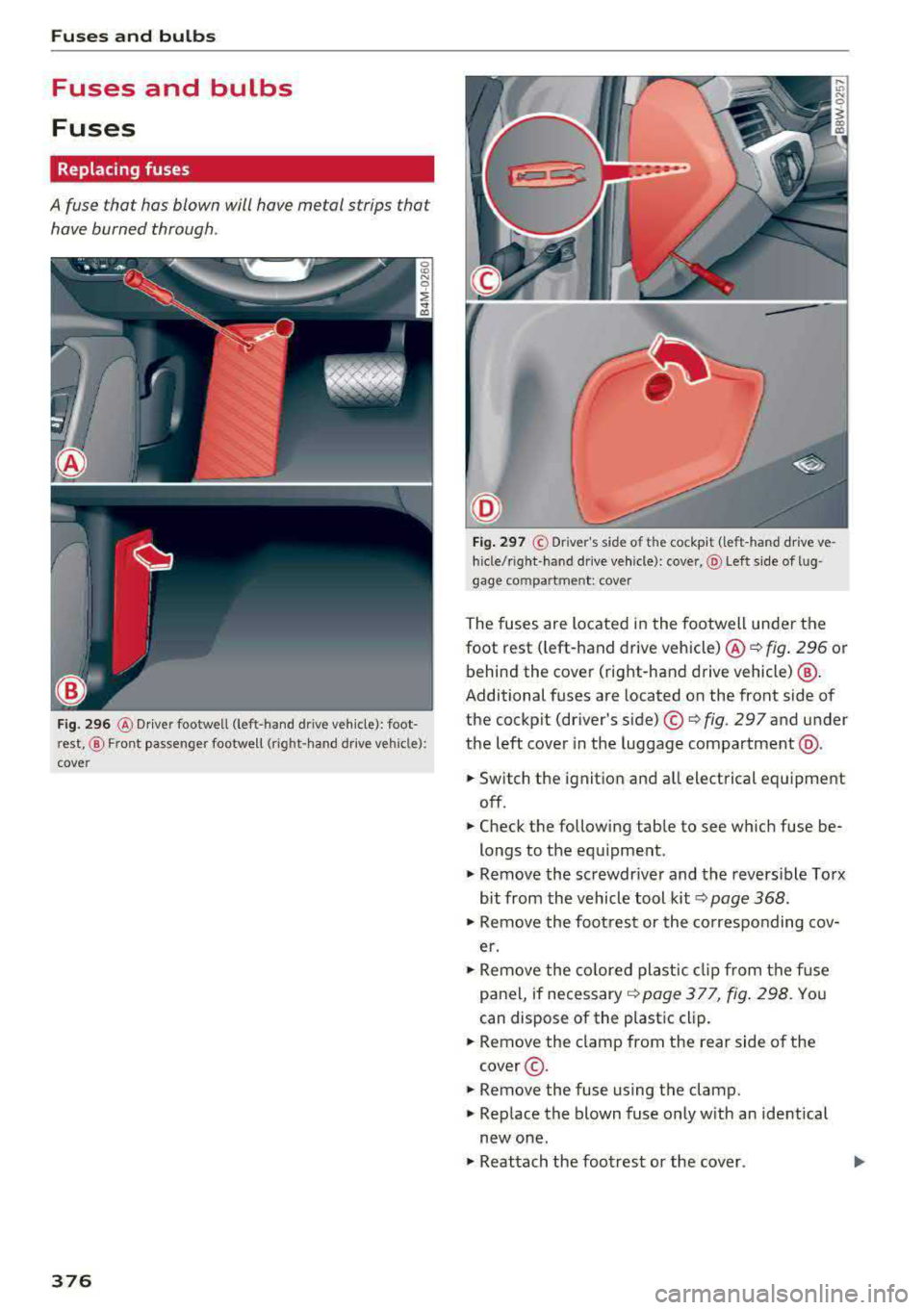
Fig. 296 @ Driver footwell (left-hand dr ive vehicle): foot
rest, ® Front passenger footwell (right -hand drive vehicle):
cover
376
Fig. 297 © Dr iver's side of the cockpit (left -hand drive ve
hicle/r ight -hand drive vehicle): cove r, @ Left side of lu g
gage compartment: cover
The fuses are located in the footwell under the
foot rest ( left-hand drive vehicle) @
¢fig. 296 or
behind the cover (right-hand drive vehicle) @.
Additional fuses are located on the front side of
the cockpit (driver's
side) ©¢ fig. 297 and under
the left cover in the luggage compartment @.
.,. Switch the ignition and all electrical equipment
off .
.,. Check the following table to see which fuse be
longs to the equipment .
.,. Remove the screwdriver and the reversible Torx
bit from the vehicle tool
kit¢ page 368 .
.,. Remove the footrest or the corresponding cov
er.
.,. Remove the colored plastic clip from the fuse
panel, if necessary
¢ page 377, fig. 298. You
can dispose of the plastic clip .
.,. Remove the clamp from the rear side of the
cover@ .
.,. Remove the fuse us ing the clamp .
.,. Replace the blown fuse only with an identical
new one .
.,. Reattach the footrest or the cover.
Page 378 of 409
Fuse colo r identification
Color Current rating
in amps
Black 1
Purp le 3
Light brown 5
Brown 7 .5
Red 10
Blue 15
Yellow 20
White or transpa ren t 25
Green 30
Orange 40
A WARNING 1=
Do not repair fuses and never replace a blown
fuse with one that has a higher amp rating.
Th is can cause damage to the electrical sys
tem and increases the r isk of fire.
(D Note
If a new fuse b urns o ut again short ly after you
have installed it, have the electrical system
checked as soon as possible by an authorized
Aud i dea le r or a uthorized Audi Service Facili
ty.
{!) Tips
- The following table does not list fuse loca
tions that are not used.
- Some of the equipment listed in the follow
i ng tables applies only to certain model ver
s ions or certain optional eq uipment.
Fuses and bulbs
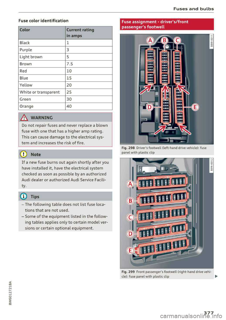
Fuse assignment - driver's/front
passenger's footwell
F ig. 298 Drive r's footwe ll (left -hand dr ive vehicle): fuse
pa nel with plas tic clip
Fig . 2 99 Front passe nge r's footwell (rig ht-h and d rive vehi -
cle): fuse panel with plastic clip
II>
377
Page 379 of 409
Fuses a nd bul bs
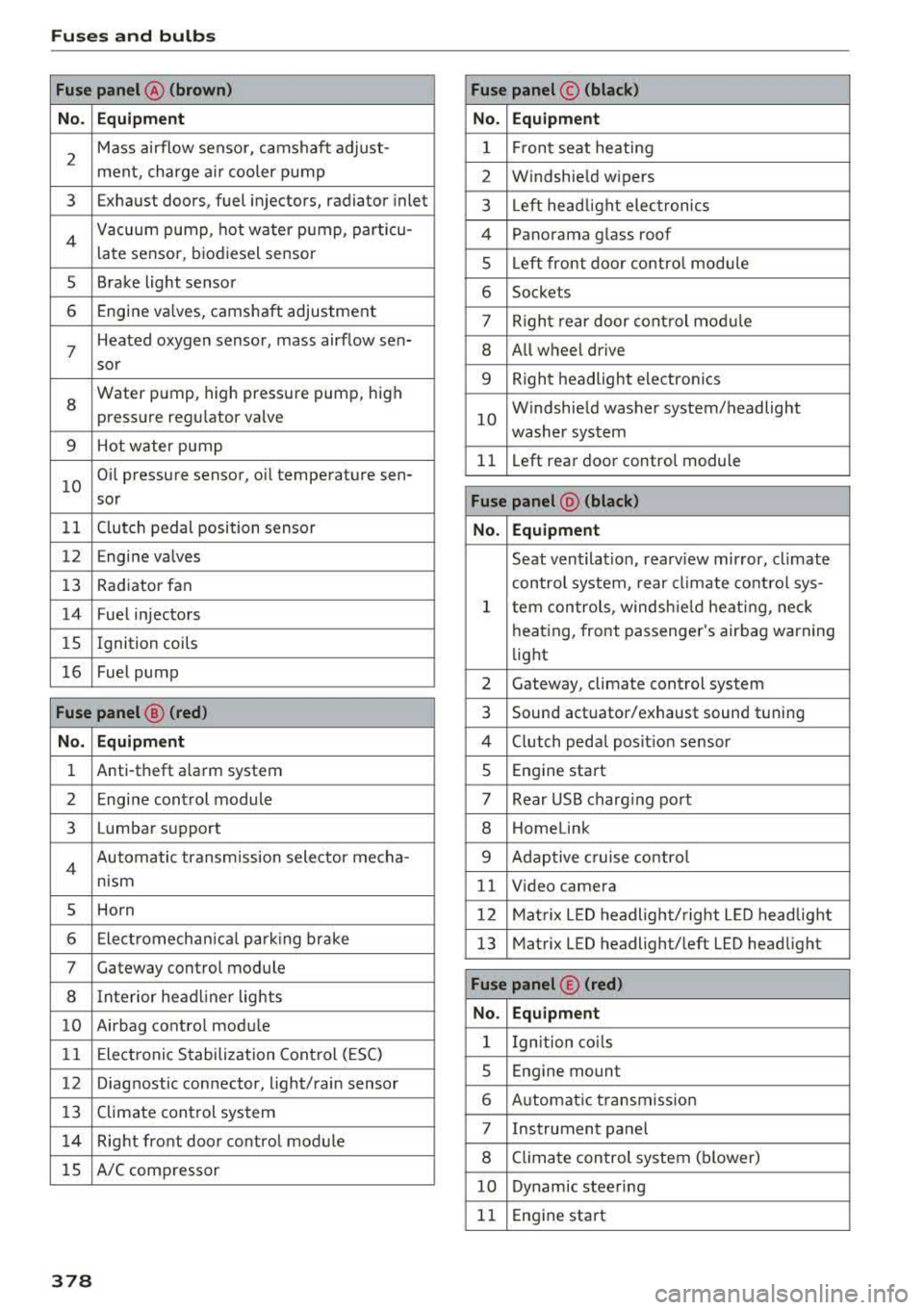
Fuse panel @ (brown) Fuse panel© (blac k)
No. Equip ment No. Equipm ent
2
Mass airflow sensor, camshaft adjust-
ment, charge air cooler pump 1 F ront seat heating
2 Windshield wipers
3 Exhaust doors, fuel injectors, radiator inlet 3 Left head light electronics
4 Vacuum pump , hot water pump, particu-
late sensor, biodiesel sensor 4 Panorama glass roof
s Left front door contro l module
5 Brake light sensor 6 Sockets
6 Engine valves, camshaft adjustment 7 Right rear door control mod ule
7
Heated oxygen sensor, mass airflow sen-8 All wheel drive
sor
8
Water pump, high pressure pump, high
pressure regulator valve
9 Hot water pump
9 Right headlight electronics
10
Windshield washer system/headlight
washer system
11 L eft rear door control module
10
Oil pressure sensor, oil temperature sen-
sor
Fu se panel @ (blac k)
11 Clutch pedal position sensor No. Equipmen t
12 Engine valves
Seat ventilation, rearv iew mirror, climate
13 Rad iator fan control system, rear climate control sys-
14 Fuel injectors
15 Ignition
coils
16 Fuel pump
1 tern controls , windsh ie ld heat ing , neck
heating, front passenger 's airbag warning
light
2 Gateway, climate control system
Fuse panel@ (red ) 3 Sound actuator/exhaust sound tuning
No. Equ ip me nt 4 Clutch pedal posit ion sensor
1 Anti-theft alarm system 5 Engine start
2 Engine control module 7 Rear USB charg ing port
3 Lumbar support 8 Homelink
4 Automatic transmission selector mecha-
nism 9 Adaptive cruise contro l
11 Video camera
5 Horn 12 Matrix LED headlight/right L ED headlight
6 Electromechan ica l park ing brake 13 Matrix LED headlight/left LED headlight
7 Gateway control module
8 Interior headl iner lights
10 Airbag control module
11 Electronic Stabilization Control (ESC)
Fuse panel © (red )
N o. Equ ipmen t
1 Ign ition co ils
12 Diagnostic connector, light/rain sensor
13 Climate control system
14 Right front door control module
lS A/C compressor
5 Engine mount
6 Automatic transmission
7 Instrument panel
8 Climate control system (blower)
10 Dynamic steering
11 Engine start
378
Page 380 of 409
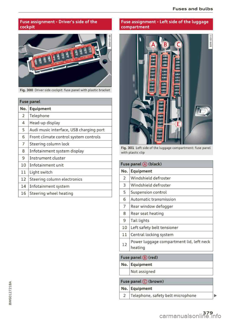
Fuse assignment - Driver's side of the
cockpit
F ig. 300 D riv er s ide cockpit: fuse panel wit h plastic bracket
Fuse panel
No . Equipment
2 Telephone
4 Head-up display
5 Audi music interface, USB charging port
6 Front climate control system contro ls
7 Steering column lock
8 Infotainment system display
9 Instrument cluster
10 Info tainment un it
11 Light switch
12 Steering column electronics
14 Infotainmen t system
16 Steering wheel heating
Fuses and bulbs
Fuse assignment - Left side of the luggage
compartment
Fig. 301 L eft side of the l uggage compartment: fuse panel
wi th plastic cl ip
Fuse panel @ (black)
No . Equipment
2 Windshield defroster
3 W indshie ld defroster
5 Suspens ion control
6 Automat ic transmission
7 Rear window
defogger
8 Rear sea t heating
9 Tail lights
10 Left safety belt tens ioner
11 Central locking system
12
Power luggage compartment lid, left neck
heating
Fuse panel @ (red)
No. Equipment
Not assigned
Fuse panel © (brown)
No . Equipment
2 Telephone, safety belt micropho ne
379