AUDI A6 1995 C5 / 2.G AHA ATQ Engines Valve Gear Workshop Manual
Manufacturer: AUDI, Model Year: 1995, Model line: A6, Model: AUDI A6 1995 C5 / 2.GPages: 62, PDF Size: 1.17 MB
Page 41 of 62
15-35
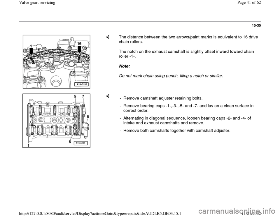
The distance between the two arrows/paint marks is equivalent to 16 drive
chain rollers.
The notch on the exhaust camshaft is slightly offset inward toward chain
roller -1-.
Note:
Do not mark chain using punch, filing a notch or similar.
- Remove camshaft adjuster retaining bolts.
- Remove bearing caps -1-,-3-,-5- and -7- and lay on a clean surface in
correct order.
- Alternating in diagonal sequence, loosen bearing caps -2- and -4- of
intake and exhaust camshafts and remove.
- Remove both camshafts together with camshaft adjuster.
Pa
ge 41 of 62 Valve
gear, servicin
g
11/21/2002 htt
p://127.0.0.1:8080/audi/servlet/Dis
play?action=Goto&t
yp
e=re
pair&id=AUDI.B5.GE03.15.1
Page 42 of 62
15-36
Installing
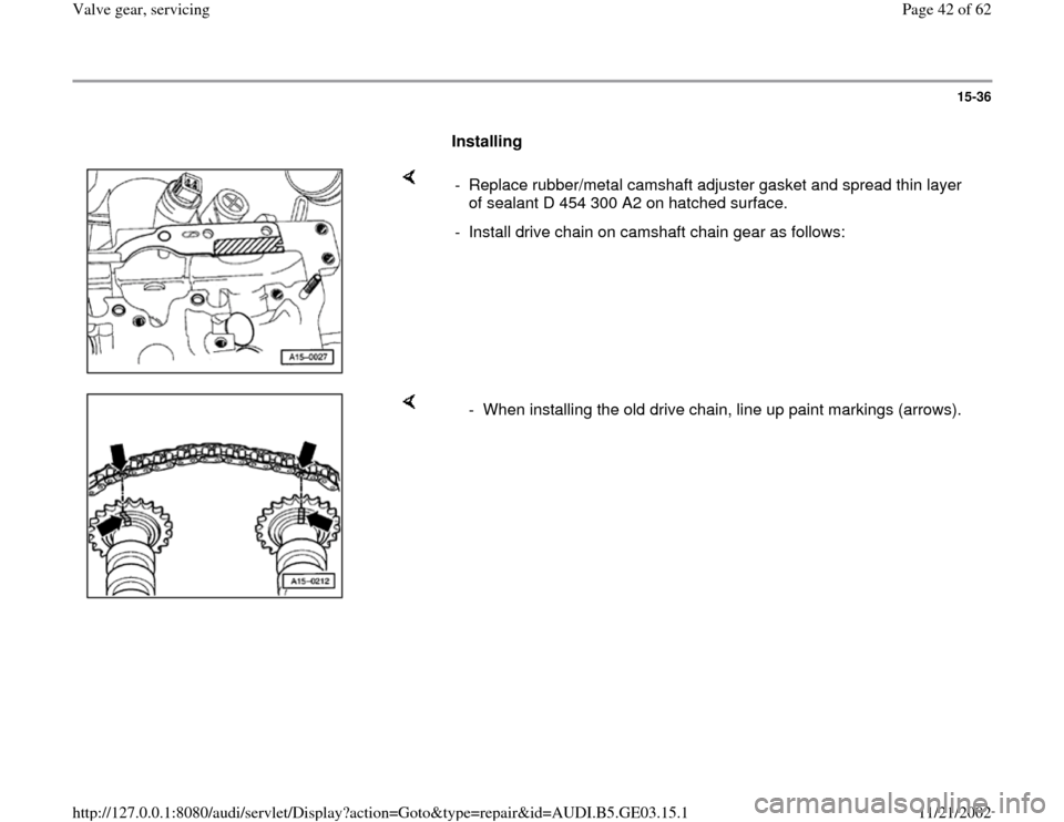
- Replace rubber/metal camshaft adjuster gasket and spread thin layer
of sealant D 454 300 A2 on hatched surface.
- Install drive chain on camshaft chain gear as follows:
- When installing the old drive chain, line up paint markings (arrows).
Pa
ge 42 of 62 Valve
gear, servicin
g
11/21/2002 htt
p://127.0.0.1:8080/audi/servlet/Dis
play?action=Goto&t
yp
e=re
pair&id=AUDI.B5.GE03.15.1
Page 43 of 62
15-37
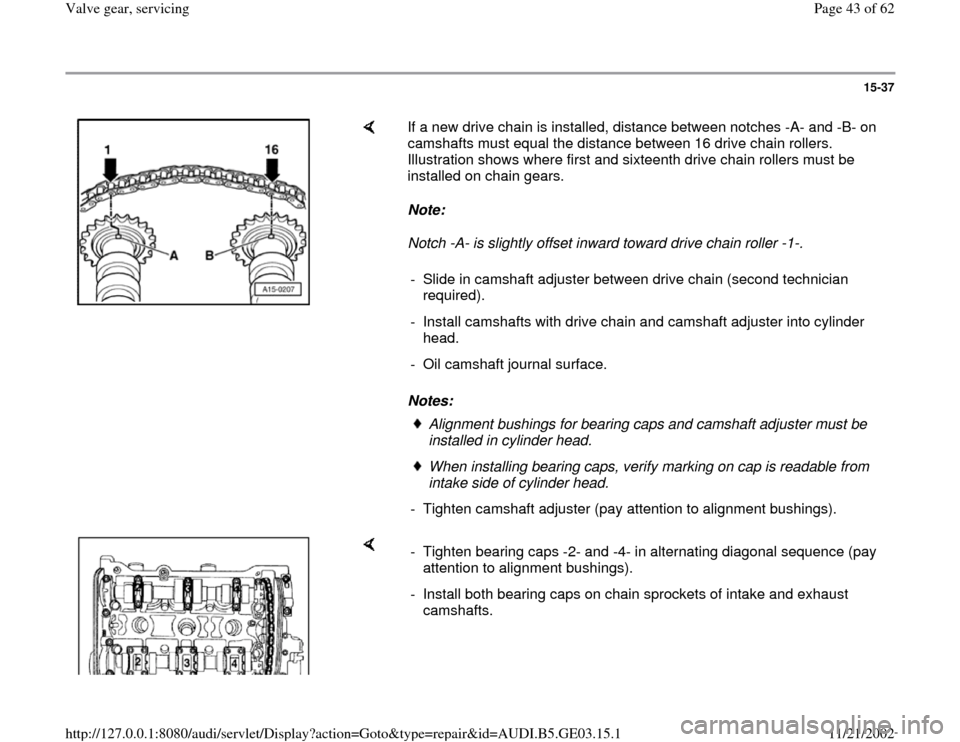
If a new drive chain is installed, distance between notches -A- and -B- on
camshafts must equal the distance between 16 drive chain rollers.
Illustration shows where first and sixteenth drive chain rollers must be
installed on chain gears.
Note:
Notch -A- is slightly offset inward toward drive chain roller -1-.
Notes: - Slide in camshaft adjuster between drive chain (second technician
required).
- Install camshafts with drive chain and camshaft adjuster into cylinder
head.
- Oil camshaft journal surface.
Alignment bushings for bearing caps and camshaft adjuster must be
installed in cylinder head. When installing bearing caps, verify marking on cap is readable from
intake side of cylinder head.
- Tighten camshaft adjuster (pay attention to alignment bushings).
- Tighten bearing caps -2- and -4- in alternating diagonal sequence (pay
attention to alignment bushings).
- Install both bearing caps on chain sprockets of intake and exhaust
camshafts.
Pa
ge 43 of 62 Valve
gear, servicin
g
11/21/2002 htt
p://127.0.0.1:8080/audi/servlet/Dis
play?action=Goto&t
yp
e=re
pair&id=AUDI.B5.GE03.15.1
Page 44 of 62
15-38
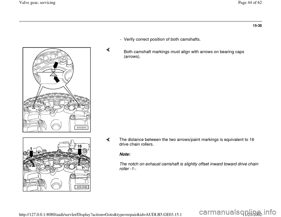
- Verify correct position of both camshafts.
Both camshaft markings must align with arrows on bearing caps
(arrows).
The distance between the two arrows/paint markings is equivalent to 16
drive chain rollers.
Note:
The notch on exhaust camshaft is slightly offset inward toward drive chain
roller -1-.
Pa
ge 44 of 62 Valve
gear, servicin
g
11/21/2002 htt
p://127.0.0.1:8080/audi/servlet/Dis
play?action=Goto&t
yp
e=re
pair&id=AUDI.B5.GE03.15.1
Page 45 of 62
15-39
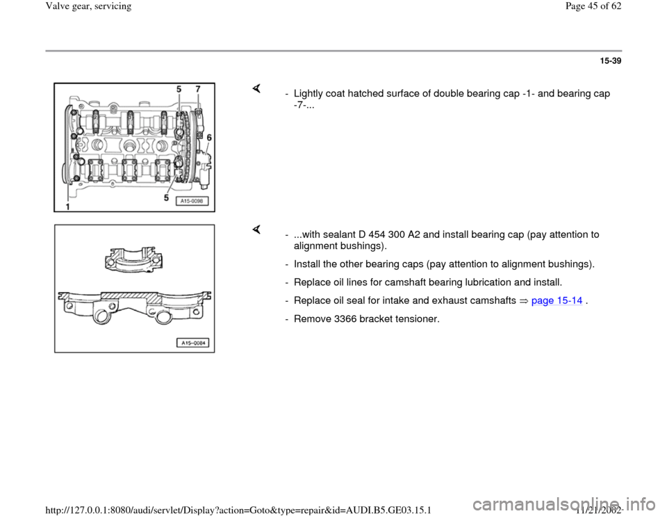
- Lightly coat hatched surface of double bearing cap -1- and bearing cap
-7-...
- ...with sealant D 454 300 A2 and install bearing cap (pay attention to
alignment bushings).
- Install the other bearing caps (pay attention to alignment bushings).
- Replace oil lines for camshaft bearing lubrication and install.
- Replace oil seal for intake and exhaust camshafts page 15
-14
.
- Remove 3366 bracket tensioner.
Pa
ge 45 of 62 Valve
gear, servicin
g
11/21/2002 htt
p://127.0.0.1:8080/audi/servlet/Dis
play?action=Goto&t
yp
e=re
pair&id=AUDI.B5.GE03.15.1
Page 46 of 62
15-40
CAUTION!
After installing new hydraulic lifters, the
engine must not be started for approx. 30
minutes. The hydraulic valve lifters have to
settle (otherwise valves will strike the
pistons).
After installing the valvetrain and lifters,
carefully rotate the crankshaft by hand at
least 2 full revolutions before starting to be
sure that valves do not strike the pistons.
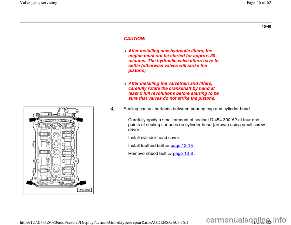
Sealing contact surfaces between bearing cap and cylinder head.
- Carefully apply a small amount of sealant D 454 300 A2 at four end
points of sealing surfaces on cylinder head (arrows) using small screw
driver.
- Install cylinder head cover.
- Install toothed belt page 13
-15
.
- Remove ribbed belt page 13
-8 .
Pa
ge 46 of 62 Valve
gear, servicin
g
11/21/2002 htt
p://127.0.0.1:8080/audi/servlet/Dis
play?action=Goto&t
yp
e=re
pair&id=AUDI.B5.GE03.15.1
Page 47 of 62
15-41
Tightening torques
Component
Tightening
torque
Bolts M6 10 Nm (7 ft
lb)
M8 20 Nm (15 ft
lb)
Except for the following:
Bearing cap to cylinder
head 10 Nm (7 ft
lb)
Camshaft adjuster to cylinder
head 10 Nm (7 ft
lb)
Shutter wheel for Camshaft
Position (CMP) sensor -G40- to
camshaft 25 Nm (18 ft
lb)
Housing for Camshaft Position
(CMP) sensor -G40- to cylinder
head 10 Nm (7 ft
lb)
Camshaft gear to
camshaft 55 Nm (41 ft
lb)
Camshaft bearing cap and
camshaft adjuster 10 Nm (7 ft
lb)
Cylinder head cover 10 Nm (7 ft
lb)
Pa
ge 47 of 62 Valve
gear, servicin
g
11/21/2002 htt
p://127.0.0.1:8080/audi/servlet/Dis
play?action=Goto&t
yp
e=re
pair&id=AUDI.B5.GE03.15.1
Page 48 of 62
15-42
Camshaft axial play, checking
- Remove camshafts page 15
-31
.
- Remove hydraulic valve lifters.
- Install camshafts without chain into cylinder
head and tighten with bearing caps 2 and 4.
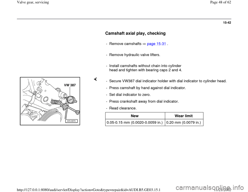
- Secure VW387 dial indicator holder with dial indicator to cylinder head.
- Press camshaft by hand against dial indicator.
- Set dial indicator to zero.
- Press crankshaft away from dial indicator.
- Read clearance.
New
Wear limit
0.05-0.15 mm (0.0020-0.0059 in.) 0.20 mm (0.0079 in.)
Pa
ge 48 of 62 Valve
gear, servicin
g
11/21/2002 htt
p://127.0.0.1:8080/audi/servlet/Dis
play?action=Goto&t
yp
e=re
pair&id=AUDI.B5.GE03.15.1
Page 49 of 62
15-43
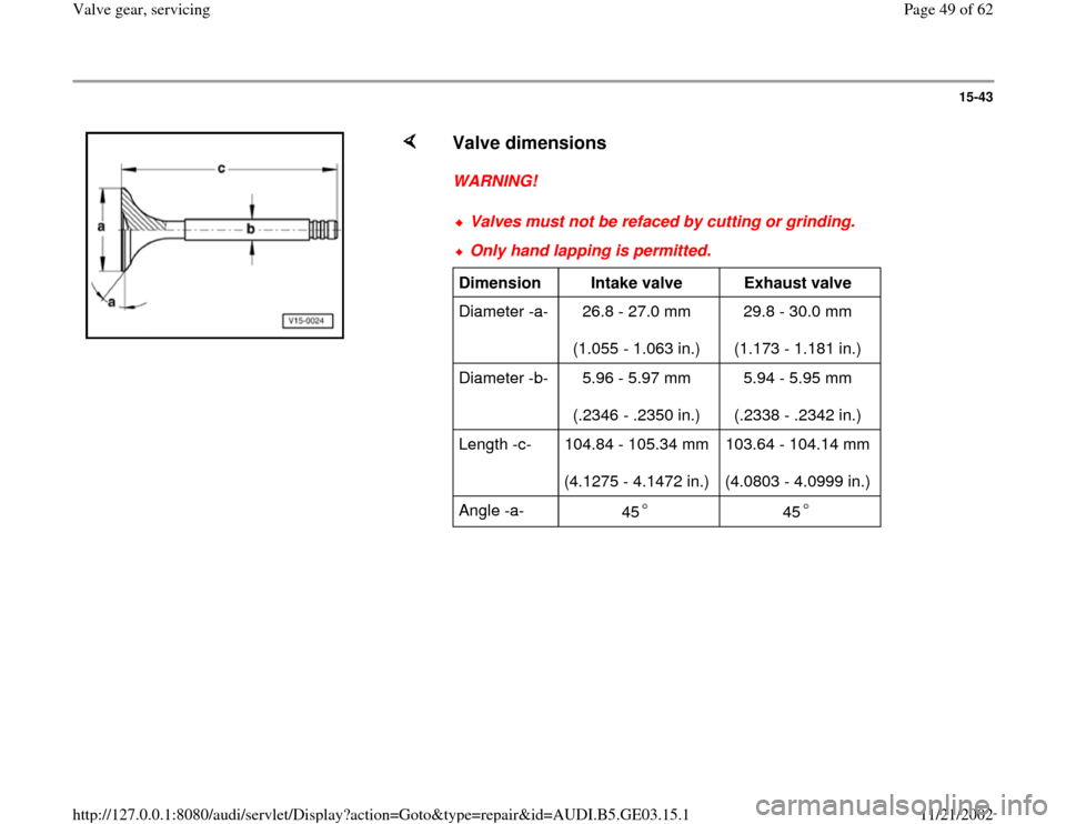
Valve dimensions
WARNING!
Valves must not be refaced by cutting or grinding.Only hand lapping is permitted.Dimension
Intake valve
Exhaust valve
Diameter -a- 26.8 - 27.0 mm
(1.055 - 1.063 in.) 29.8 - 30.0 mm
(1.173 - 1.181 in.)
Diameter -b- 5.96 - 5.97 mm
(.2346 - .2350 in.) 5.94 - 5.95 mm
(.2338 - .2342 in.)
Length -c- 104.84 - 105.34 mm
(4.1275 - 4.1472 in.) 103.64 - 104.14 mm
(4.0803 - 4.0999 in.)
Angle -a-
45
45
Pa
ge 49 of 62 Valve
gear, servicin
g
11/21/2002 htt
p://127.0.0.1:8080/audi/servlet/Dis
play?action=Goto&t
yp
e=re
pair&id=AUDI.B5.GE03.15.1
Page 50 of 62
15-44
WARNING!
Sodium-filled exhaust valves must not be
scrapped without first being properly treated.
The valves must be cut open using a
hacksaw, by hand, between the valve head
and the middle of the stem.
The valves must not come into any contact
with water while being cut.
After cutting open the valves, throw not more
than 10 at a time into a bucket of water and
step back. A sudden chemical reaction will
occur during which the sodium filling is
consumed.
Valves that have been treated in this way can
be disposed of as normal waste.
Pa
ge 50 of 62 Valve
gear, servicin
g
11/21/2002 htt
p://127.0.0.1:8080/audi/servlet/Dis
play?action=Goto&t
yp
e=re
pair&id=AUDI.B5.GE03.15.1