AUDI A6 1995 C5 / 2.G AHA ATQ Engines Valve Gear Owner's Guide
Manufacturer: AUDI, Model Year: 1995,
Model line: A6,
Model: AUDI A6 1995 C5 / 2.G
Pages: 62, PDF Size: 1.17 MB
AUDI A6 1995 C5 / 2.G AHA ATQ Engines Valve Gear Owner's Guide
A6 1995 C5 / 2.G
AUDI
AUDI
https://www.carmanualsonline.info/img/6/995/w960_995-0.png
AUDI A6 1995 C5 / 2.G AHA ATQ Engines Valve Gear Owner's Guide
Trending: transmission, radiator, ECU, oil change, sensor, air condition, check engine
Page 31 of 62
15-26
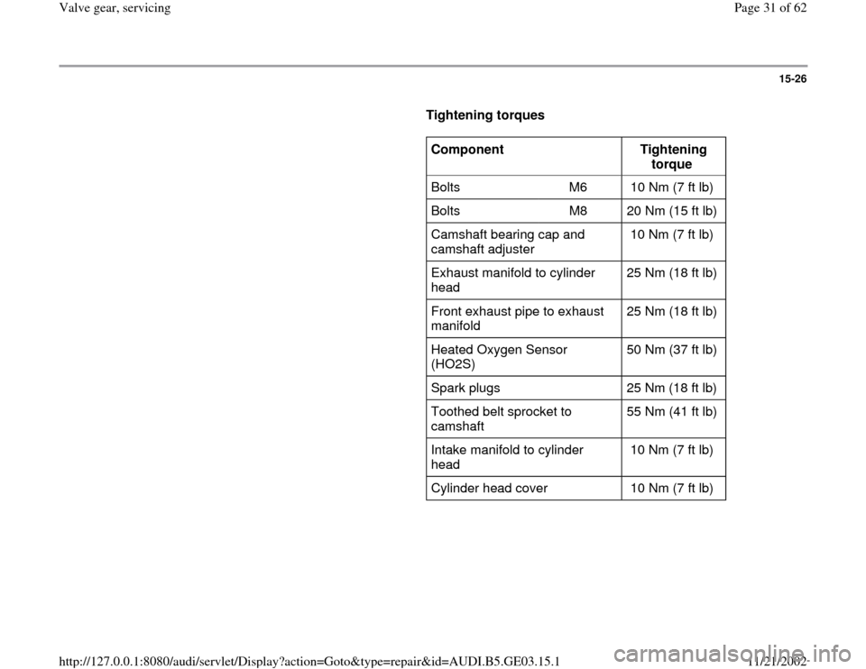
Tightening torques
Component
Tightening
torque
Bolts M6 10 Nm (7 ft lb)
Bolts M8 20 Nm (15 ft lb)
Camshaft bearing cap and
camshaft adjuster 10 Nm (7 ft lb)
Exhaust manifold to cylinder
head 25 Nm (18 ft lb)
Front exhaust pipe to exhaust
manifold 25 Nm (18 ft lb)
Heated Oxygen Sensor
(HO2S) 50 Nm (37 ft lb)
Spark plugs 25 Nm (18 ft lb)
Toothed belt sprocket to
camshaft 55 Nm (41 ft lb)
Intake manifold to cylinder
head 10 Nm (7 ft lb)
Cylinder head cover 10 Nm (7 ft lb)
Pa
ge 31 of 62 Valve
gear, servicin
g
11/21/2002 htt
p://127.0.0.1:8080/audi/servlet/Dis
play?action=Goto&t
yp
e=re
pair&id=AUDI.B5.GE03.15.1
Page 32 of 62
15-27
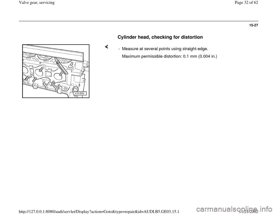
Cylinder head, checking for distortion
- Measure at several points using straight-edge.
Maximum permissible distortion: 0.1 mm (0.004 in.)
Pa
ge 32 of 62 Valve
gear, servicin
g
11/21/2002 htt
p://127.0.0.1:8080/audi/servlet/Dis
play?action=Goto&t
yp
e=re
pair&id=AUDI.B5.GE03.15.1
Page 33 of 62
15-28
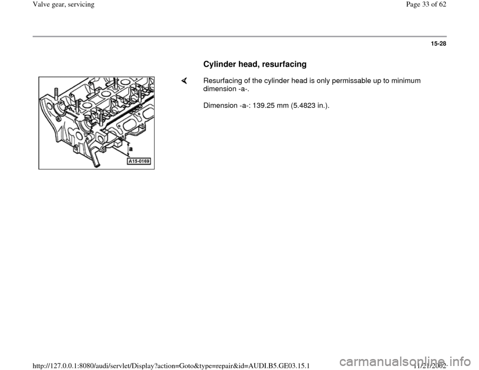
Cylinder head, resurfacing
Resurfacing of the cylinder head is only permissable up to minimum
dimension -a-.
Dimension -a-: 139.25 mm (5.4823 in.).
Pa
ge 33 of 62 Valve
gear, servicin
g
11/21/2002 htt
p://127.0.0.1:8080/audi/servlet/Dis
play?action=Goto&t
yp
e=re
pair&id=AUDI.B5.GE03.15.1
Page 34 of 62
15-29
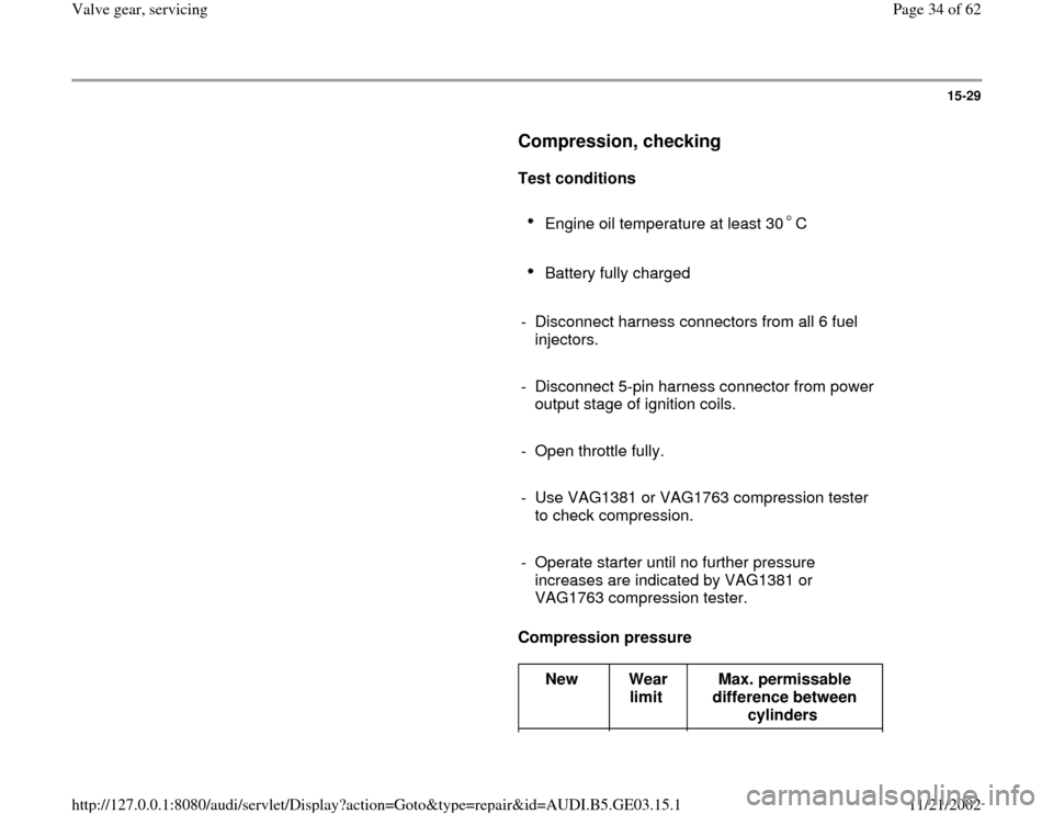
Compression, checking
Test conditions
Engine oil temperature at least 30 C
Battery fully charged
- Disconnect harness connectors from all 6 fuel
injectors.
- Disconnect 5-pin harness connector from power
output stage of ignition coils.
- Open throttle fully.
- Use VAG1381 or VAG1763 compression tester
to check compression.
- Operate starter until no further pressure
increases are indicated by VAG1381 or
VAG1763 compression tester.
Compression pressure
New
Wear
limit Max. permissable
difference between
cylinders
Pa
ge 34 of 62 Valve
gear, servicin
g
11/21/2002 htt
p://127.0.0.1:8080/audi/servlet/Dis
play?action=Goto&t
yp
e=re
pair&id=AUDI.B5.GE03.15.1
Page 35 of 62
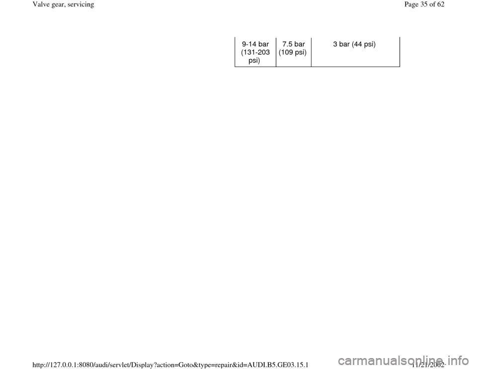
9-14 bar
(131-203
psi) 7.5 bar
(109 psi) 3 bar (44 psi)
Pa
ge 35 of 62 Valve
gear, servicin
g
11/21/2002 htt
p://127.0.0.1:8080/audi/servlet/Dis
play?action=Goto&t
yp
e=re
pair&id=AUDI.B5.GE03.15.1
Page 36 of 62
15-30
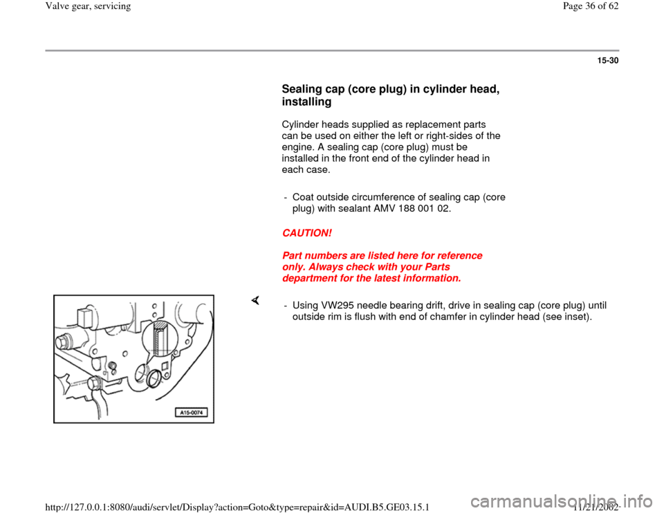
Sealing cap (core plug) in cylinder head,
installing
Cylinder heads supplied as replacement parts
can be used on either the left or right-sides of the
engine. A sealing cap (core plug) must be
installed in the front end of the cylinder head in
each case.
- Coat outside circumference of sealing cap (core
plug) with sealant AMV 188 001 02.
CAUTION!
Part numbers are listed here for reference
only. Always check with your Parts
department for the latest information.
- Using VW295 needle bearing drift, drive in sealing cap (core plug) until
outside rim is flush with end of chamfer in cylinder head (see inset).
Pa
ge 36 of 62 Valve
gear, servicin
g
11/21/2002 htt
p://127.0.0.1:8080/audi/servlet/Dis
play?action=Goto&t
yp
e=re
pair&id=AUDI.B5.GE03.15.1
Page 37 of 62
15-31
Camshafts and camshaft adjusters,
removing and installing
Removing
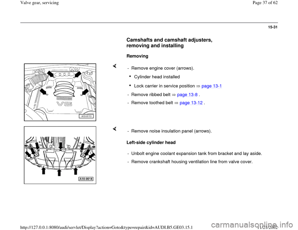
- Remove engine cover (arrows).
Cylinder head installed Lock carrier in service position page 13
-1
- Remove ribbed belt page 13
-8 .
- Remove toothed belt page 13
-12
.
Left-side cylinder head - Remove noise insulation panel (arrows).
- Unbolt engine coolant expansion tank from bracket and lay aside.
- Remove crankshaft housing ventilation line from valve cover.
Pa
ge 37 of 62 Valve
gear, servicin
g
11/21/2002 htt
p://127.0.0.1:8080/audi/servlet/Dis
play?action=Goto&t
yp
e=re
pair&id=AUDI.B5.GE03.15.1
Page 38 of 62
15-32
Right-side cylinder head
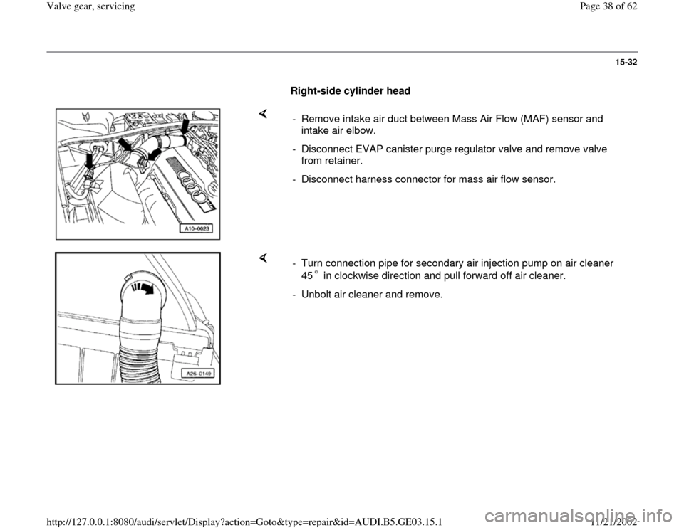
- Remove intake air duct between Mass Air Flow (MAF) sensor and
intake air elbow.
- Disconnect EVAP canister purge regulator valve and remove valve
from retainer.
- Disconnect harness connector for mass air flow sensor.
- Turn connection pipe for secondary air injection pump on air cleaner
45 in clockwise direction and pull forward off air cleaner. - Unbolt air cleaner and remove.
Pa
ge 38 of 62 Valve
gear, servicin
g
11/21/2002 htt
p://127.0.0.1:8080/audi/servlet/Dis
play?action=Goto&t
yp
e=re
pair&id=AUDI.B5.GE03.15.1
Page 39 of 62
15-33
All models
- Remove Camshaft Position (CMP) sensor
housing and shutter wheel.
- Unbolt shutter wheel for Camshaft Position
(CMP) sensor -G40- and carefully pry out using
screwdriver.
Tightening torque: 20Nm (15 ft lb)
- Remove cylinder head cover.
- Install 3391 camshaft locator bar into camshaft
locking plates.
- Loosen both bolts for camshafts and back out
bolts approx. 5 turns.
- Remove 3391 camshaft locator bar.
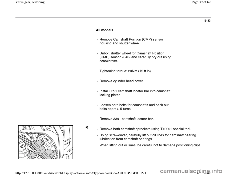
- Remove both camshaft sprockets using T40001 special tool.
- Using screwdriver, carefully lift out oil lines for camshaft bearing
lubrication from camshaft bearings.
When lifting out oil lines, be careful not to damage positioning clips.
Pa
ge 39 of 62 Valve
gear, servicin
g
11/21/2002 htt
p://127.0.0.1:8080/audi/servlet/Dis
play?action=Goto&t
yp
e=re
pair&id=AUDI.B5.GE03.15.1
Page 40 of 62
15-34
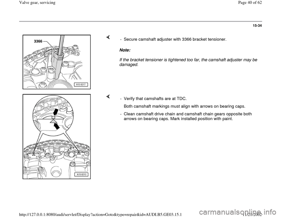
Note:
If the bracket tensioner is tightened too far, the camshaft adjuster may be
damaged. - Secure camshaft adjuster with 3366 bracket tensioner.
- Verify that camshafts are at TDC.
Both camshaft markings must align with arrows on bearing caps.
- Clean camshaft drive chain and camshaft chain gears opposite both
arrows on bearing caps. Mark installed position with paint.
Pa
ge 40 of 62 Valve
gear, servicin
g
11/21/2002 htt
p://127.0.0.1:8080/audi/servlet/Dis
play?action=Goto&t
yp
e=re
pair&id=AUDI.B5.GE03.15.1
Trending: wheel torque, air condition, seats, radiator, wheel bolts, fuel, engine coolant
