service AUDI A6 2005 C5 / 2.G Electrics System Training Manual
[x] Cancel search | Manufacturer: AUDI, Model Year: 2005, Model line: A6, Model: AUDI A6 2005 C5 / 2.GPages: 92, PDF Size: 4.42 MB
Page 1 of 92

Downloaded from www.Manualslib.com manuals search engine 326
All rights reserved.
Subject to
technical change.
Copyright
AUDI AG
I/VK-35
[email protected]
Fax +49-841/89-36367
AUDI AG
D-85045 Ingolstadt
Technical release 01/04
Printed in Germany
A04.5S00.09.20
Audi A6 ‘05 – Electrics
Self-Study Programme 326
Vorsprung durch Technik www.audi.co.uk
Service Training
Page 11 of 92

Downloaded from www.Manualslib.com manuals search engine Audi
Audi A6 2005>
2005 (5)
Saloon
BBJ 3.0l Motronic / 160 kW Guided fault-finding
Function/component selection
Selecting a function or component
Electrical system (Rep. Gr. 01; 90 - 97)
01 – Self-diagnosis systems
61 – Battery control
J644 – Control unit for power management, Functions
A – Battery, Charge level
A – Battery, Battery testing
J644 – Power management, General description
J644 – Control unit for power management, Coding
J644 – Read out history data
J644 – Power management, Read measured-value blocks
J644 – Power management, Query fault memory
J644 – Data link tests for generator voltage
J644 – Replace control unit
J644 – Power management, Activate/deactivate Transport mode
Battery change history
Data for the last three battery changes is stored.
Power balance history – driving (= engine on)
The power balance and duration of the last five
journeys are logged.
Power balance history – idle (= engine off)
The power balance and duration of the last five idle
times are logged.
Other data is not relevant for Customer Service.
History dataThe diagnosis tester can be used to read out
data from the control unit for power management,
which makes it much easier to analyse the on-board
power supply and the battery.
Open-circuit voltage history
If the battery open-circuit voltage is less than the
threshold values of 12.5 volts, 12.2 volts and
11.5 volts, an entry is written to the history data.
The last four entries can always be read out.
Voltage measurement starts when
– CAN Convenience is in Sleep mode and
– terminal 15 is switched off for at least 2 hours
and
– the vehicle’s power consumption is < 100 mA.
Voltage measurement ends when
– the voltage increases or
– the current increases or
– the control unit triggers Sleep mode or
– the control unit detects a new battery.
Closed-circuit current history
If the closed-circuit current exceeds the threshold
value of 50 mA, an entry is written to the history
data. The last ten entries can be read out.
Current measurement starts when
– CAN Convenience is in Sleep mode and
– terminal 15 is switched off for at least 2 hours
and
– the vehicle’s power consumption is > 50 mA.
Current measurement ends when
– the current decreases or
– the control unit triggers Sleep mode.
Breakdown analysis
If the control unit for power management detects
the status "Cannot start vehicle", an entry is written
to the history data.
Cut-off level history
Data for the last 15 cut-off levels is stored.
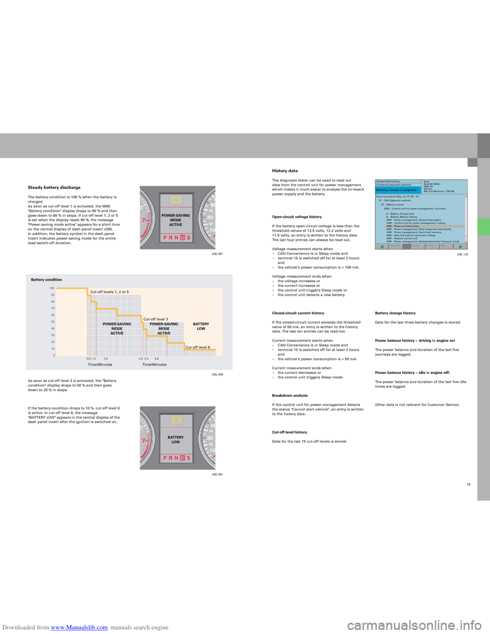
Steady battery dischargeThe battery condition is 100 % when the battery is
charged.
As soon as cut-off level 1 is activated, the MMI
"Battery condition" display drops to 90 % and then
goes down to 60 % in steps. If cut-off level 1, 2 or 5
is set when the display reads 90 %, the message
"Power-saving mode active" app ears fo r a sho r t time
on the central display of dash panel insert J285.
In addition, the battery symbol in the dash panel
insert indicates power-saving mode for the entire
load switch-off duration.
As soon as cut-off level 3 is activated, the "Battery
condition" display drops to 50 % and then goes
down to 20 % in steps.
If the battery condition drops to 10 %, cut-off level 6
is active. In cut-off level 6, the message
"B AT TERY LOW" appears in the central di splay of the
dash panel insert after the ignition is switched on.
326_061 326_061
326_036
POWER-SAVING
MODE
ACTIVE
BATTERY
LOW
Battery condition
Cut-off levels 1, 2 or 5
Cut-off level 3
POWER-SAVING
MODE
ACTIVEBATTERY
LOW
Time/MinutesCut-off level 6
Time/MinutesPOWER-SAVING
MODE
ACTIVE
12 326_123
Page 49 of 92

Downloaded from www.Manualslib.com manuals search engine 51
The control unit for wiper motor J400 was
redesigned for use in the new Audi A6 ’05. As is
already the case in the Audi A8 ‘03 and Audi A3 ’04,
the control unit and wiper motor are integrated into
one housing.
It is linked to the control unit for on-board power
supply J519 as a LIN-slave control unit.
Functions
– Intermittent
– Intermittent stages (four)
–One-touch wiping
– Wiper function stage 1
– Wiper function stage 2
– Wipe over again 5 seconds after the last
wash-and-wipe action
(at vehicle speed > 5 km/h only)
– Rain sensor function (see Sensor for rain and
light detection G397)
– Service setting
– Alternating parking position (can be coded)
Function diagram
G397 Sensor for rain and light detection
J400 Control unit for wiper motor
J519 Control unit for on-board power supply
Reference
For further information on the control unit
for wiper motor J400, please refer to the
SSP 287, Audi A8 ‘03 – Electrical
Components.
Note
The control unit for on-board power
supply J519 now activates the windscreen
washer pump V5.
326_081
Control unit for wiper motor J400
326_104
Page 85 of 92

Downloaded from www.Manualslib.com manuals search engine 87
The telephone transmitter and receiver R36 is fitted
as standard with a Bluetooth module.
In principle, the Bluetooth functionality
is always available, even if a mobile phone holder is
not connected. For reasons of electromagnetic
compatibility, Bluetooth is only active at present
when the mobile phone is inserted into the relevant
holder. The phonebook stored on the mobile phone
SIM card is read into the memory of the Telephone
transmitter and receiver R36 whenever the mobile
phone is inserted. Mobile-internal phonebooks
cannot be read in because the data formats differ
from model to model. The mobile baseplate is operated via the MMI in the
"TEL" menu. The telephone holder R126, which is
required for whichever type of mobile phone is to be
used, is available from the Parts Service. As you may
already know from the introduction of the new
mobile baseplate in other model series (Audi A3, A4,
TT), this mobile phone holder no longer has a
connection cable. It is connected to the telephone
transmitter and receiver R36 via a contact panel.
Voice operation
The new mobile baseplate can be voice-operated
using the operating unit in the steering wheel E221.
The handsfree volume can also be set using the
multi-function steering wheel and names or
telephone numbers can be dialled in the
phonebook. The operating unit in the steering
wheel E22 1 passes the data si gnals fo r this on to the
steering column electrics J527 as LIN signals.
This control unit converts the data into CAN
messages and transfers these messages to the data
bus diagnosis interface J533 on CAN Convenience.
Here, the digital data messages are converted into
MOST data records and are passed to the telephone
transmitter and receiver R36 via the MOST ring.
The adapter set always includes a Push-to-talk
button (PTT), which enables voice operation even
without the multi-function steering wheel option.
This button is included on every available mobile
phone adapter.
The PTT button has different functionalities,
depending on the MMI used:
– MMI High: Accept/Hang up
– MMI Basic/Basic Plus/Basic Navigation:
Accept/Hand up and also
Activate internal voice operation of the
telephone transmitter and receiver R36.
This internal voice operation function is only
available in the MMI Basic versions. Voice operation
in the MMI High version is implemented via the
optional control unit for voice input J507.
326_106
This illustration depicts the service handset for the fixed telephone
installation (MMI High) and the alternative universal mobile
baseplate with the mobile adapter. A vehicle cannot be fitted with
both systems!
Page 92 of 92

Downloaded from www.Manualslib.com manuals search engine 326
All rights reserved.
Subject to
technical change.
Copyright
AUDI AG
I/VK-35
[email protected]
Fax +49-841/89-36367
AUDI AG
D-85045 Ingolstadt
Technical release 01/04
Printed in Germany
A04.5S00.09.20
Audi A6 ‘05 – Electrics
Self-Study Programme 326
Vorsprung durch Technik www.audi.co.uk
Service Training