ESP AUDI A6 2005 C5 / 2.G Electrics System Training Manual
[x] Cancel search | Manufacturer: AUDI, Model Year: 2005, Model line: A6, Model: AUDI A6 2005 C5 / 2.GPages: 92, PDF Size: 4.42 MB
Page 11 of 92

Downloaded from www.Manualslib.com manuals search engine Audi
Audi A6 2005>
2005 (5)
Saloon
BBJ 3.0l Motronic / 160 kW Guided fault-finding
Function/component selection
Selecting a function or component
Electrical system (Rep. Gr. 01; 90 - 97)
01 – Self-diagnosis systems
61 – Battery control
J644 – Control unit for power management, Functions
A – Battery, Charge level
A – Battery, Battery testing
J644 – Power management, General description
J644 – Control unit for power management, Coding
J644 – Read out history data
J644 – Power management, Read measured-value blocks
J644 – Power management, Query fault memory
J644 – Data link tests for generator voltage
J644 – Replace control unit
J644 – Power management, Activate/deactivate Transport mode
Battery change history
Data for the last three battery changes is stored.
Power balance history – driving (= engine on)
The power balance and duration of the last five
journeys are logged.
Power balance history – idle (= engine off)
The power balance and duration of the last five idle
times are logged.
Other data is not relevant for Customer Service.
History dataThe diagnosis tester can be used to read out
data from the control unit for power management,
which makes it much easier to analyse the on-board
power supply and the battery.
Open-circuit voltage history
If the battery open-circuit voltage is less than the
threshold values of 12.5 volts, 12.2 volts and
11.5 volts, an entry is written to the history data.
The last four entries can always be read out.
Voltage measurement starts when
– CAN Convenience is in Sleep mode and
– terminal 15 is switched off for at least 2 hours
and
– the vehicle’s power consumption is < 100 mA.
Voltage measurement ends when
– the voltage increases or
– the current increases or
– the control unit triggers Sleep mode or
– the control unit detects a new battery.
Closed-circuit current history
If the closed-circuit current exceeds the threshold
value of 50 mA, an entry is written to the history
data. The last ten entries can be read out.
Current measurement starts when
– CAN Convenience is in Sleep mode and
– terminal 15 is switched off for at least 2 hours
and
– the vehicle’s power consumption is > 50 mA.
Current measurement ends when
– the current decreases or
– the control unit triggers Sleep mode.
Breakdown analysis
If the control unit for power management detects
the status "Cannot start vehicle", an entry is written
to the history data.
Cut-off level history
Data for the last 15 cut-off levels is stored.
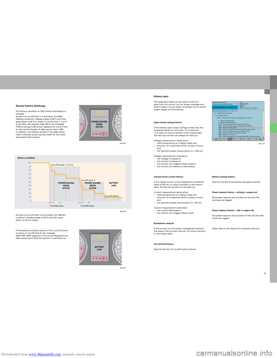
Steady battery dischargeThe battery condition is 100 % when the battery is
charged.
As soon as cut-off level 1 is activated, the MMI
"Battery condition" display drops to 90 % and then
goes down to 60 % in steps. If cut-off level 1, 2 or 5
is set when the display reads 90 %, the message
"Power-saving mode active" app ears fo r a sho r t time
on the central display of dash panel insert J285.
In addition, the battery symbol in the dash panel
insert indicates power-saving mode for the entire
load switch-off duration.
As soon as cut-off level 3 is activated, the "Battery
condition" display drops to 50 % and then goes
down to 20 % in steps.
If the battery condition drops to 10 %, cut-off level 6
is active. In cut-off level 6, the message
"B AT TERY LOW" appears in the central di splay of the
dash panel insert after the ignition is switched on.
326_061 326_061
326_036
POWER-SAVING
MODE
ACTIVE
BATTERY
LOW
Battery condition
Cut-off levels 1, 2 or 5
Cut-off level 3
POWER-SAVING
MODE
ACTIVEBATTERY
LOW
Time/MinutesCut-off level 6
Time/MinutesPOWER-SAVING
MODE
ACTIVE
12 326_123
Page 31 of 92

Downloaded from www.Manualslib.com manuals search engine 33
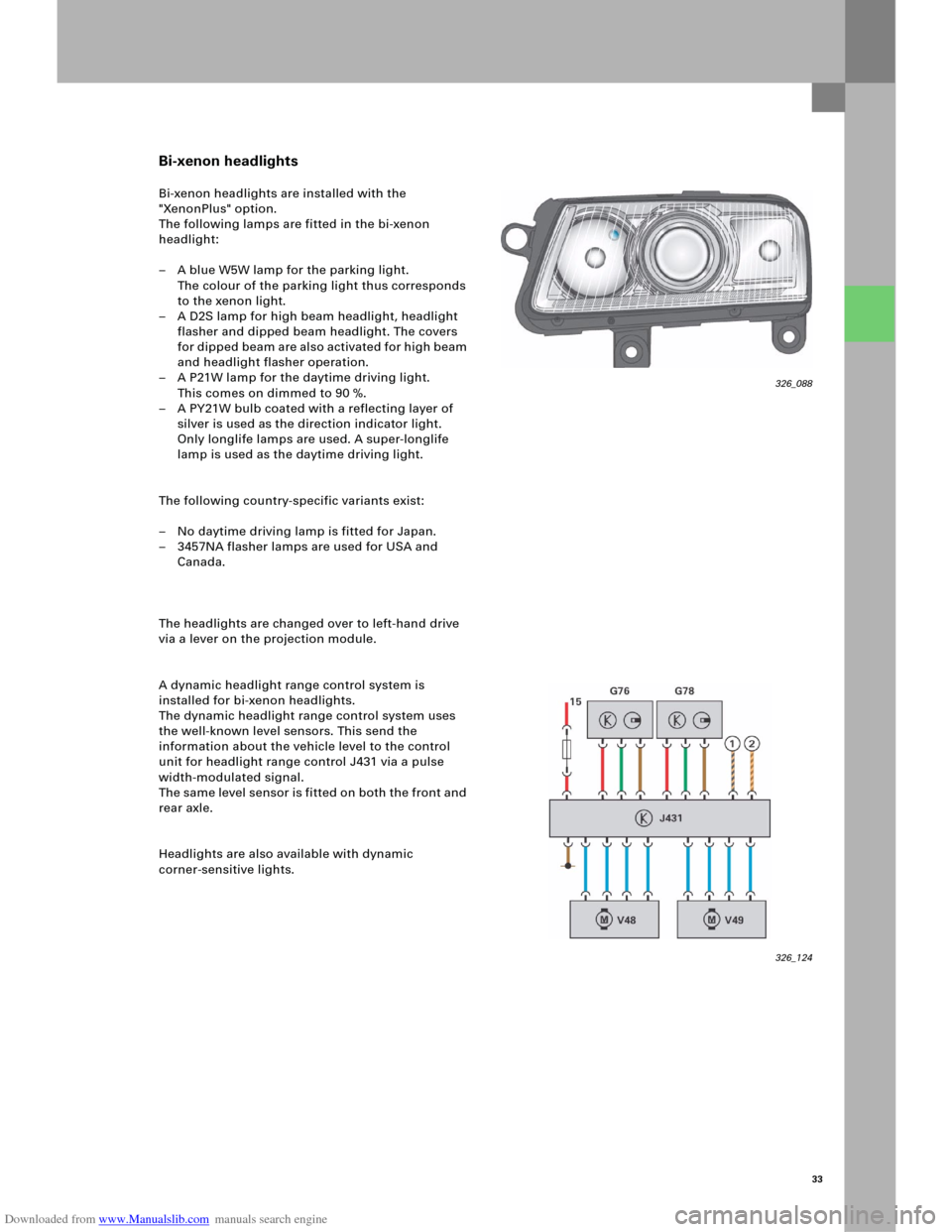
Bi-xenon headlights
Bi-xenon headlights are installed with the
"XenonPlus" option.
The following lamps are fitted in the bi-xenon
headlight:
– A blue W5W lamp for the parking light.
The colour of the parking light thus corresponds
to the xenon light.
– A D2S lamp for high beam headlight, headlight
flasher and dipped beam headlight. The covers
fo r d i p p ed b e am a re al s o a c t i v at e d fo r h i gh b ea m
and headlight flasher operation.
– A P21W lamp for the daytime driving light.
This comes on dimmed to 90 %.
– A PY21W bulb coated with a reflecting layer of
silver is used as the direction indicator light.
Only longlife lamps are used. A super-longlife
lamp is used as the daytime driving light.
The following country-specific variants exist:
– No daytime driving lamp is fitted for Japan.
– 3457NA flasher lamps are used for USA and
Canada.
The headlights are changed over to left-hand drive
via a lever on the projection module.
A dynamic headlight range control system is
installed for bi-xenon headlights.
The dynamic headlight range control system uses
the well-known level sensors. This send the
information about the vehicle level to the control
unit for headlight range control J431 via a pulse
width-modulated signal.
The same level sensor is fitted on both the front and
rear axle.
Headlights are also available with dynamic
corner-sensitive lights.
326_088
326_124
Page 57 of 92

Downloaded from www.Manualslib.com manuals search engine 59
326_120
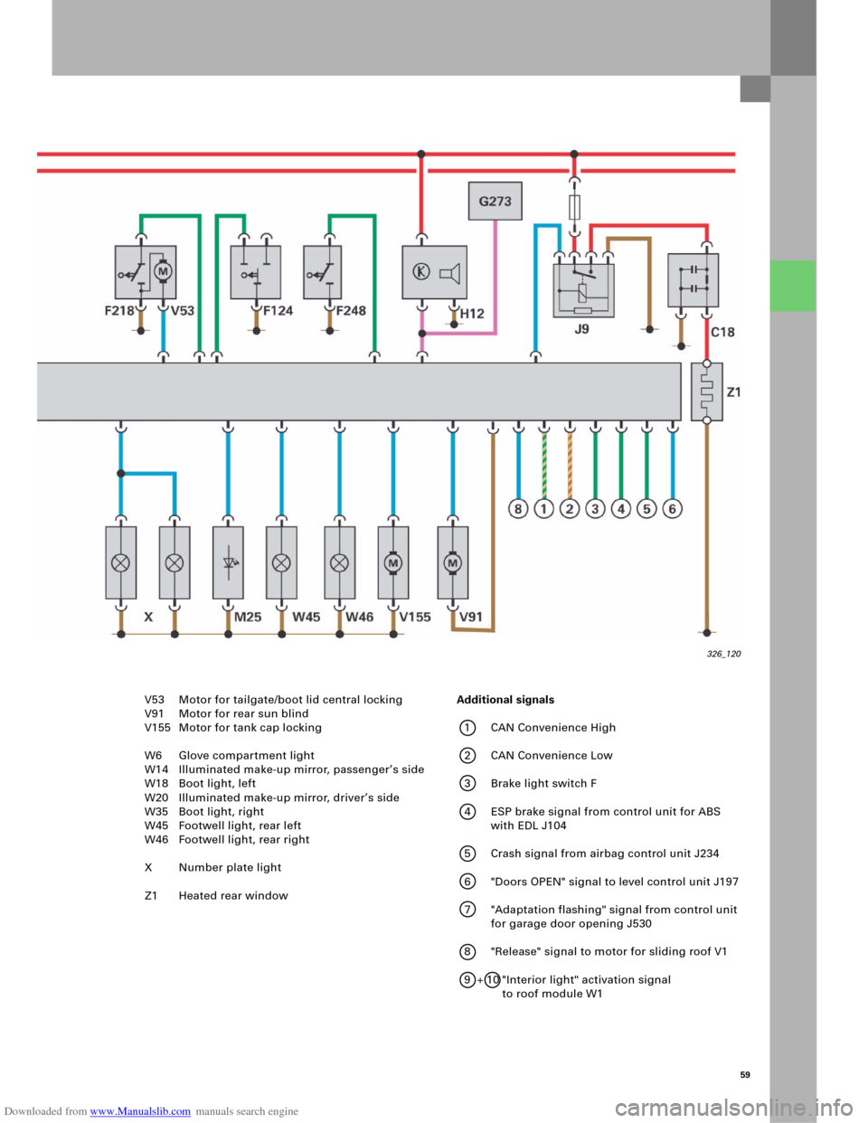
V53 Motor for tailgate/boot lid central locking
V91 Motor for rear sun blind
V155 Motor for tank cap locking
W6 Glove compartment light
W14 Illuminated make-up mirror, passenger’s side
W18 Boot light, left
W20 Illuminated make-up mirror, driver’s side
W35 Boot light, right
W45 Footwell light, rear left
W46 Footwell light, rear right
X Number plate light
Z1 Heated rear window Additional signals
1CAN Convenience High
2CAN Convenience Low
3 Brake light switch F
4 ESP brake signal from control unit for ABS
with EDL J104
5 Crash signal from airbag control unit J234
6 "Doors OPEN" signal to level control unit J197
7 "Adaptation flashing" signal from control unit
for garage door opening J530
8 "Release" signal to motor for sliding roof V1
9 + 10 "Interior light" activation signal
to roof module W1
Page 65 of 92

Downloaded from www.Manualslib.com manuals search engine 67
Seat symmetry positioning
The "Symmetry positioning, driver’s seat/
passenger’s seat" option, which is available in the
MMI, can be used to move the passenger’s seat into
a symmetrical position in relation to the driver’s
seat. The MMI sends a corresponding instruction to
the driver’s seat control unit via the
CAN Convenience bus. The control unit then sends
the current seat position and a control instruction to
the passenger’s seat control unit, which positions
its motors accordingly.
Comfort side view
The "Comfort side view" option moves the
passenger’s seat into a position that hides the
vehicle’s B-pillar, thereby ensuring that the driver
has the best possible view out of the vehicle.
The function can be selected via the MMI, where the
signal is transmitted in the same way as for the
"Seat symmetry positioning" function.
Memory retrieval
Radio code memory
Memory settings are retrieved using the radio code. Personal button memory
Settings are retrieved and stored using the memory
buttons in the door panel.
The stored memory settings can be retrieved in
the following ways.
326_138
326_116
Page 73 of 92

Downloaded from www.Manualslib.com manuals search engine 75
Antenna systems
The antenna system in the new Audi A6 ´05 is
integrated as a module in the top area of the rear
window, to the left and next to the third brake light,
on the right.
The modules are responsible for the various
s y s t e m s, e . g . re m o t e c e n t ral lo ck i n g , rad i o , T V o r t h e
radio receiver for the auxiliary heater.
Only the modules that are required for the
requested optional extras are installed.The table shows the relevant modules for the
available vehicle equipment. These are indicated for
the various, worldwide country versions.
The modules "DAB" and "SDARS" relate to the digital
radio systems, which will be available later and are
based on either a satellite-controlled system
(SDARS) or a terrestrial system (DAB).
ModuleDesignationAvailable in market version
1
1
1
1
2
4
2
2
2
3
4
5
5
5
5
7
8Radio AM/FM
Radio AM/FM-Diversity
Radio AM/FM-Div/TV
Radio AM/FM-Div/TV
Remote central locking
Remote control for auxiliary heater
Remote locking/TV
Remote locking/TV/DAB
Remote central locking/TV
Navigation
Mobile phone-US
Te l e p h o n e E C E
Telephone (fixed or mobile)/Navigation
Telephone/Navigation
Satellite radio
Block circuit
Te l e p a s sECE
ECE/US
ECE/US
Japan
ECE/US
ECE
ECE/US
ECE
Japan
RoW
US
ECE
ECE
US
US
Italy
Installed antenna modules for possible vehicle equipment
Module 1
Module 3 Module 4Module 2 Module 5
Module 7Module 6
A
M
/F
M
-Di
v/
TV
1-2Third brake lightT
V3-
4
/R
emot
e
c
ent
ra
l
locking/R
C
/DA
B
326_125
Module 1: Radio/antenna amplifier R24
Module 2: Remote central locking/antenna amplifier 2 R111
Module 3: GPS/antenna for GPS navigation R50
Module 4: Mobile phone antenna USA/Antenna for telephone,
navigation, auxiliary heater R66Module 5: Roof antenna/antenna for radio, telephone,
navigation R52
Module 6: Block circuit
Module 7: Telepass antenna
Page 78 of 92

Downloaded from www.Manualslib.com manuals search engine 80
Versions: Basic, Basic Plus and
Basic Navigation
Infotainment
Decimal
placeDescription
1.Country version: D, GB, USA, F, E, I, P
2.Equipment: ACC, Internal light package, Acoustic parking system, front
3.Equipment: Acoustic parking system, rear, Tyre pressure control system, Air suspension
4.Equipment: Seat memory, front/rear, Left-hand drive
5.Equipment: Standard sound system installation, Body variant, Leather equipment
6.Equipment: On-board computer
7.Reserved
Infotainment control unit holder
In the new Audi A6 ’05, the control units responsible
for Infotainment are mainly stored in a compact
holder behind the left wheel cut-out in the boot.
Only the control unit for front information J523 is
installed in the dash panel, either in a visible
position in the glove compartment (Basic version) or
behind the glove compartment (High version). The
dual-band compensator, the mobile phone
amplifier R86, is fitted on the rear right wheel well.
Reference
Please refer to the relevant Workshop Manual
for details of the exact individual installation
positions.
Coding variants of the control unit for front information J523
326_105
Page 91 of 92

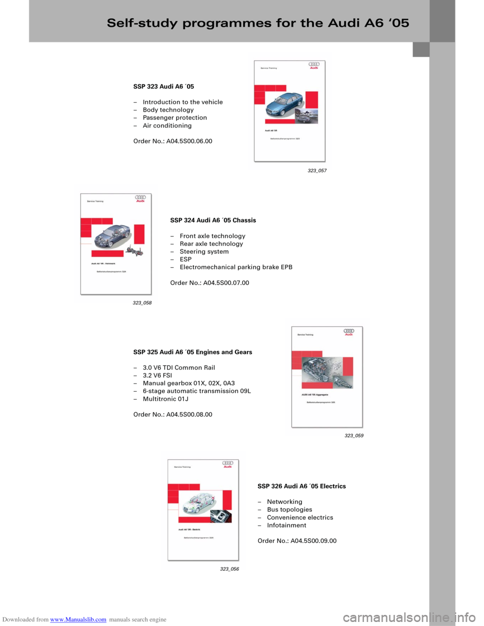
Downloaded from www.Manualslib.com manuals search engine SSP 324 Audi A6 ´05 Chassis
– Front axle technology
– Rear axle technology
– Steering system
–ESP
– Electromechanical parking brake EPB
Order No.: A04.5S00.07.00
SSP 326 Audi A6 ´05 Electrics
–Networking
– Bus topologies
– Convenience electrics
– Infotainment
Order No.: A04.5S00.09.00 SSP 323 Audi A6 ´05
– Introduction to the vehicle
–Body technology
– Passenger protection
– Air conditioning
Order No.: A04.5S00.06.00
SSP 325 Audi A6 ´05 Engines and Gears
– 3.0 V6 TDI Common Rail
–3.2 V6 FSI
– Manual gearbox 01X, 02X, 0A3
– 6-stage automatic transmission 09L
– Multitronic 01J
Order No.: A04.5S00.08.00
Self-study programmes for the Audi A6 ‘05
323_057
323_058
323_059
323_056