display AUDI A6 2011 Owner's Manual
[x] Cancel search | Manufacturer: AUDI, Model Year: 2011, Model line: A6, Model: AUDI A6 2011Pages: 370, PDF Size: 87.15 MB
Page 33 of 370
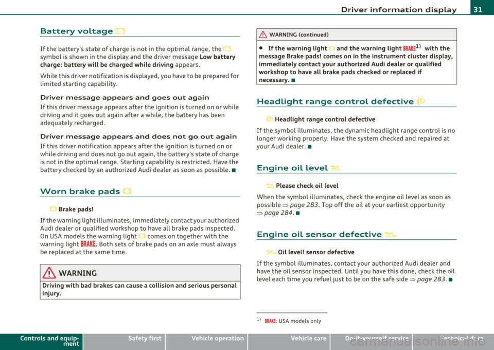
Battery voltage 1• i
If the battery's state of charge is not in the optima l range, the
symbo l is show n in the di splay and the d river me ssage
Low battery
charge: battery will be charged while dri ving
appears.
Whi le this d river notification is displayed, you have to be prepared for
limited starting capability .
Driver message appears and goes out again
If this driver message appears after the ignition is turned on or while
driving and it goes o ut again afte r a while, the ba ttery has been
adequate ly recharged.
Driver me ssage appears and does not go out again
If th is dr iver notification appears after the ignition is turned on or
wh ile driving and does not go ou t aga in, the battery 's state o f charge
is not in the opt imal range . Starting capability is restricted. Have the
bat tery checked by an au thor ized A udi dea le r as soon as possible. •
Worn brake pads U
._ Brake pads!
If the war ning lig ht ill um inates, immediately co ntact your au tho rized
Audi dea ler or qualified wor kshop to have all brake pads inspected.
On USA mode ls the warn ing light comes on together w it h the
warning light
BRAKE . Both sets of brake pads on an axle must a lways
be re placed at th e same time.
& WARNING
Driving with bad brakes can cause a collision and serious personal
injury .
Controls and equip
ment Safety first
Driver information display
& WARNING
(co ntinued )
• If the warning light... and the warning light BRAKE1l with the
mes sage Brake pads! comes on in the instrument cluster di splay,
immediately contact your authorized Audi dealer or qualified
workshop to have all brake pads checked or replaced if necessary. •
Headlight range control defective ((
~ ~ Headlight range control defective
If the symbo l illumina tes, the dynam ic he adlig ht r an ge con tro l is no
longer working properly. Have the system checked and repaired at
your Audi de aler. •
Engine oil Level~
Please che ck oil level
Whe n the symbol i llumina tes, check t he engine o il level as soo n as
poss ible => page 283 . Top off the oil at yo ur earlies t oppor tunity
=>page284 .•
Engine oil sensor defective _t..
Oi l level! sensor defective
If the symbo l illuminates, contact your author ized A udi dealer and
have the oi l senso r inspected. Un til you have t his don e, check the oil
level each time you refue l just to be on the safe side => page 283. •
ll BRAKE : USA mode ls only
Vehicle care Technical data
Page 34 of 370
Driver information display
Applies to veh icles : w ith eng ine s peed limitat ion
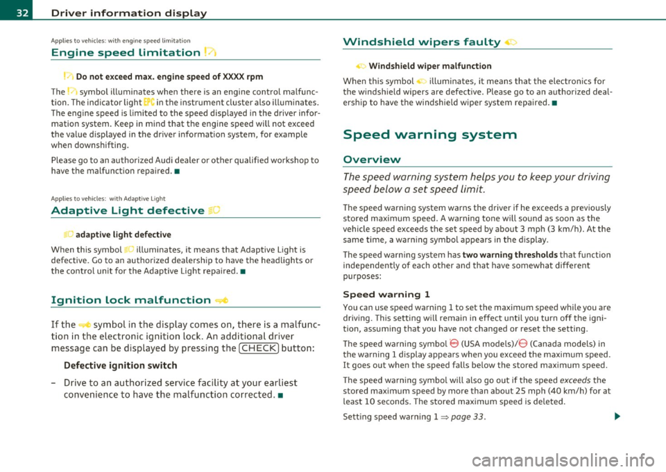
Engine speed limitation .?i
11'1 Do not exceed max. engine speed of XXXX rpm
The -symbol illuminates when there is an engine control malfunc
tion. The indicator light in the instrument cluster also illuminates.
The engine speed is limited to the speed displayed in the driver infor
mation system. Keep in mind that the engine speed will not exceed
the value d isp layed in the drive r informat ion system, for example
when downshifting.
Please go to an authorized Audi dealer or other qualified workshop to
have the malfunction repaired.•
Applies to vehicles: wi th Adap tive Light
Adaptive Light defective
adaptive light defective • r
When this symbol illuminates, it means that Adaptive Light is
defective. Go to an authorized dealership to have the headlights or
the control unit for the Adaptive Light repaired. •
Ignition lock malfunction ..e
If the symbol in the display comes on, there is a malfunc-
t ion in the electronic ignition lock. An additional driver
message can be displayed by pressing the [CHECK] button:
Defective ignition switch
-Drive to an aut horized service facility at your earliest
convenience to have the malfunction corrected.•
Windshield wipers faulty , . .>
.... Windshield wiper malfunction
When this symbol . illuminates, it means that the electronics for
the windshield wipers are defective . Please go to an authorized deal
ership to have the windshield wiper system repaired. •
Speed warning system
Overview
The speed warning system helps you to keep your driving
speed below a set speed limit.
Th e speed warning system warns the driver if he exceeds a previously
stored maximum speed. A warning tone will sound as soon as the
vehicle speed exceeds the set speed by about 3 mph (3 km/h). At the
same time, a warning symbol appears in the display.
The speed warning system has
two warning thresholds that function
independently of each other and that have somewhat different
purposes :
Speed warning 1
You can use speed warning 1 to set the maximum speed while you are
driving. This setting w ill remain in effect until you turn off the igni
tion, assum ing that you have not changed or reset the setting .
Th e speed warning symbo l
'8 (USA models)/ 8 (Canada mode ls) in
the warning 1 display appears when you exceed the maximum speed.
It goes out when the speed falls be low the stored maximum speed.
Th e speed warning symbol will also go out if the speed
exceeds the
stored maximum speed by more than about 25 mph (40 km/h) for at
least 10 seconds. The stored maximum speed is deleted.
Sett ing speed warn ing 1
=> page 33. ~
Page 35 of 370
Speed warning 2
Storing war ning 2 is recommended i f you o/woyswantto be reminded
of a certain speed, fo r example when you are travel ing in a country
that has a genera l maximum speed limit, or if you do not want to
exceed a specified speed fo r winter tires .
The speed warning 2 symbol,
8 , (USA mode ls)/ 8, (Canada models)
appears in the display when you exceed the stored speed limi t. Unlike
warning 1, it will not go out until the vehicle speed drops below the
sto red speed limi t.
Setting speed warn ing 2
=> page 33 .
(I) Tips
Even though your ve hicle is eq uipped with a speed war ning system,
you should st ill watch the speedometer to make sure you are no t
dr iv ing faste r th an the speed lim it. •
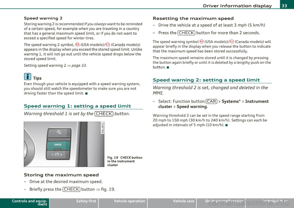
Speed warning 1: setting a speed Limit
Warning threshold 1 is set by the [ CH ECK] button .
Storing the maximum speed
-Drive at the desired max imum speed .
Fig. 19 CHE CK butt on
in the i nstrument
clu ste r
- Briefly pre ss the [CHECK] button ~ fig. 19.
Con tro ls a nd e quip
m en t Vehicle
OP-eration
Driver information display
Resetting the maximum speed
- Drive the vehic le at a speed of at leas t 3 mph (S k m/h)
- Press the [ CH EC K] button for more t han 2 seconds .
The speed warning symbo l 8 (USA models)/ 8 (Canada models) will
appea r briefly in the d ispl ay when you release the bu tton to indica te
that the maximum speed has been stored successf ully.
Th e maximum spee d rema ins s tored until it is cha nged by p ressing
the button again briefly or until it is deleted by a lengthy push o n the
bu tton .•
Speed warning 2: setting a speed Limit
Warning threshold 2 is set, changed and deleted in the
fv1fv1l.
- Select: Funct io n button [CAR ]> Systems* > Instrument
cluster > Speed warning .
Warning threshold 2 can be set in the speed range starting from
20 mph to 150 mph (30 km/ h to 240 km/h). Settings can each be
adjusted in intervals of 5 mph (10 km/h). •
Vehicle care Do-it-yourselt service iTechnical data
Page 36 of 370
Driver information display
Trip computer
Introduction
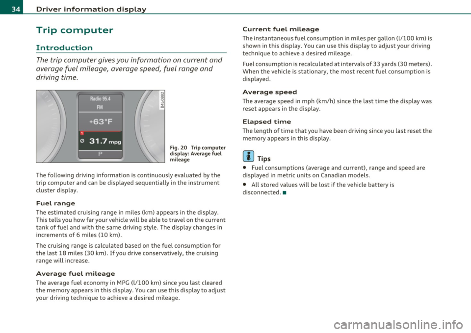
The trip computer gives you information on current and
average fuel mileage, avera ge speed, fuel range and
driving time .
Fig . 2 0 Tri p c om pute r
di sp la y: Av erag e fuel
mile age
T he fo llow ing driving information is continuously eva luated by the
t rip co mpute r and can be displayed se quen tially in the instr ument
cl uster d isplay.
Fuel range
The estimated cru ising range in miles (km) appea rs in the display.
Thi s tells you how far your veh icle w ill be ab le to travel o n the cur rent
tank of fuel a nd w ith the same driving sty le . The display changes in
in cremen ts of 6 miles (1 0 km).
Th e cru ising range is calc ulated based on t he f uel consumption for
the last 18 mi les (30 km). I f yo u drive conservatively, the cruising
r an ge will increase.
Average fuel mileage
T he average fuel economy in MPG (l/100 km) s ince you last clea red
the memory appears in this display . You can use this display to adjust
your dr iv ing tech nique to achieve a des ired mileage .
Current fuel mileage
The ins tan taneous fuel consumption in miles pe r ga llon (l/ 100 km) is
shown in this display . You can use t his disp lay to ad jus t your d riving
technique to achieve a desired m ileage.
Fuel consumpt io n is reca lculated at inte rvals of 33 y ards (30 me te rs).
When the veh icle is stationary, the most recent fue l consumption is
disp laye d.
Average speed
Th e average s peed in mph (km/h) since t he last ti me the display was
reset appea rs i n the display .
Elapsed time
The length of time that you have been dr iving since you last reset the
memory appea rs in this display.
[I) Tips
• Fuel consump tions ( average and cu rrent), range a nd speed are
displayed in metr ic units on Canad ian models.
• All stored values will be lost if the vehi cle battery is
disconnected. •
Page 37 of 370
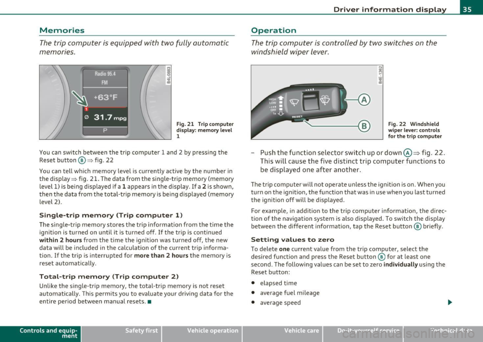
Memories
The trip computer is equipped with two fully automatic
memories .
Fig. 21 T rip c omput er
di spl ay : m emory l evel
1
You ca n switch be twee n the t rip computer 1 a nd 2 by p ressing the
Rese t button @=> fig. 22
You can tell wh ich memory level is currently active by the number in
the display => fig . 21 . The data from t he single-trip memory (memory
level 1) is be ing d isp layed if a
1 appea rs in the display . If a 2 is shown,
then t he data from the total-trip memory is being displayed (memory
level 2) .
Single-trip memory (Trip computer 1 )
The sing le-tr ip memory sto res the trip informat ion from the t ime the
ign ition is turned on unt il it is t urned off .
If the trip is cont inued
within 2 hour s from the time the ignition was turned off, the new
data will be included in the ca lculation of the current tr ip informa
tion .
If the tri p is interrup ted for more than 2 hours t he memory is
reset automatically.
Total-trip memory (Trip computer 2)
Unlike the single-trip memory, the total-tr ip memory is not reset
au tomatically. This pe rmit s you to eva luate yo ur driv ing data fo r the
entire period between manual resets. •
Contro ls a nd e quip
m en t Vehicle
OP-eration
Driver information display
Operation
The trip comp uter is controlle d by two swit che s on the
w ind shield wi per lev er.
Fig . 22 W indsh ield
w ipe r lev er: co nt rol s
fo r the trip compute r
-Push the fu nctio n se le ctor sw itch up or down @~ fig . 22 .
Thi s will cause th e five d ist inc t trip c om puter func tion s to
be dis played o ne aft er anoth er.
The trip com puter w ill not oper ate u nless the igni tion is on. When you
turn o n the ignit ion, the function that was in use when you last turned
t he igni tion off w ill be dis played.
For example , in add it ion to the trip compu ter informat io n, the direc
tion of the navigation system is a lso d is p layed . To switch t he display
be tween the different info rmation, tap the Reset butt on @ briefly .
Setting values to zero
To dele te one c ur rent value from the tr ip computer, select the
desired f unct io n an d press the Reset b utton ® for at least one
second . The following values can be set to zero
individually using the
Reset b utton :
• elapsed time
• average fuel mileage
• average speed
Vehicle care Do-it-yourselt service iTechnical data
Page 38 of 370
![AUDI A6 2011 Owners Manual Driver information display
In addit io n, all the values in the single -trip or t he total-tr ip memory
c an be delete d sim ultaneously.
[ i ] Tips
All stored values will be lost AUDI A6 2011 Owners Manual Driver information display
In addit io n, all the values in the single -trip or t he total-tr ip memory
c an be delete d sim ultaneously.
[ i ] Tips
All stored values will be lost](/img/6/57593/w960_57593-37.png)
Driver information display
In addit io n, all the values in the single -trip or t he total-tr ip memory
c an be delete d sim ultaneously.
[ i ] Tips
All stored values will be lost if the vehicle battery is disco nnected .•
MMI settings
B asic s ettings for the trip computer can b e made in the
MMI.
-Select: Funct ion button I CAR] > Systems *> Instrument
cluster > On-board computer 1 or On-board computer 2 .
The values in the s ingle-trip or the total-tr ip memory can all be reset
t o ze ro at the same t ime u nder
Reset in t he me nu.
In addit ion, you can determine w hat information from t he tr ip
compu ter should be shown in the ins trument cl uste r display. If one
of the p ieces of dr ive r info rmation is tur ned
Off, that dr ive r informa
t ion will not be shown in t he di sp lay . The i nformation w ill contin ue to
be ca lculated by the t rip compu ter and can be tur ned bac k
On at any
time. •
Page 41 of 370
Check Light in the master key
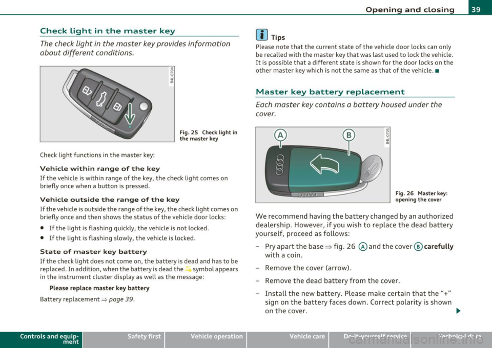
The check light in the master key provides information
about different conditions.
Check light functions in the master key :
Vehicle within range of the key
Fig . 25 C heck lig ht in
the m aster k ey
If the vehicle is w ith in range of the key, the check light comes on
briefly once w hen a button is pressed.
Vehicle outside the range of the key
If the veh icle is outside t he range of the key, the c hec k light comes on
briefly once and then shows the status of the vehicle door locks:
• If the light is fl as hi ng q uickly, the veh icle is not locked.
• If the light is f lashing slow ly, the vehicle is locked .
State of master key battery
If the check light does not come on, the battery is dea d and has to be
replaced . I n addition, when the battery is dead the symbol appea rs
i n the instrument cluste r display as well as the message :
Please replace ma ster ke y battery
Battery replacement~ page 39.
Con tro ls a nd e quip
m en t Vehicle
OP-eration
Opening and closing
(I) Tips
Please note that the c urrent state of the vehicle doo r locks can only
be recalled wit h the master key t hat was last used to lock the vehicle.
It is poss ib le tha t a d ifferen t state is shown fo r the door lo cks on the
other master key which is not the same as that of the vehicle .•
Master key battery replacement
Each mas ter key contains a battery hous ed under th e
cover.
Fi g. 26 Master key:
o pe ning the c ove r
We reco mmend having the ba ttery chang ed by an au thori zed
dealer ship . However , if you wi sh to replace th e dead b atte ry
yourse lf, proc eed as follows :
- Pry apart the base~ fig. 26 @and the
cover @carefully
with a c oin.
- Remove the cover (arrow).
- Remove the dead battery from the cover .
- Install th e new ba ttery . Please make c ertain that the"+"
sign on t he ba ttery faces down . Correct po lar ity is shown
o n the cover. .,,.
Vehicle care Do-it-yourselt service iTechnical data
Page 60 of 370
Clear vision
Clear vision
Lights
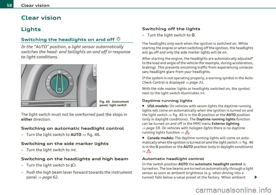
Switching the headlights on and off ·"ti-·
In the "AUTO" position, a light sensor automatically
switches the head- and taillights on and off in response to light condi tions.
Fi g. 46 In strument
p an el: li gh t swit ch
The ligh t switc h must not be overtur ned past t he stops in
either d irection.
Switching on automatic headlight control
- Turn the lig ht sw itch to AUTO => fig. 46 .
Switching on the side marker lights
-Turn the lig ht swi tch to ~oo~.
Switching on the headlights and high beam
- Tur n the lig ht sw itch to ~D.
- Push the high beam leve r forward tow ards the in strument
panel=>
page 62 .
Switching off the lights
- Tu rn th e lig ht swi tch to 0.
T he headlights on ly work when the ignitio n is switc hed on. Whi le
starting the engine or w hen switching off t he ignition, the headlig hts
w ill go off and o nly the s ide marke r lights will be o n.
After starting the eng ine, the headlights are automatically adjusted*
to the load and angle o f th e vehicle (for example, during acce lerat ion,
brak ing) . This prevents oncom ing traff ic from experiencing unneces
sary headlight glare from your head lig hts.
If the system is not operat ing p roperly, a warning symbol in the Auto
Check Control is displayed=>
page 31.
With the side marker lights o r headlights switc hed on, the symbol
next to the light switch illum inates
':o oc .
Daytime running lights
• USA models: On vehicles w ith xenon lights the dayt ime runn ing
lights will come on automat ica lly when the ignition is turned o n and
the light switch=> fig. 46 is i n the
O position or the AUTO position
(only i n day light conditions) . The
D aytime running light s function
can be turned on and off in the MMI menu
Exterior lighting
=> page 59. On vehicles wit h halogen lights there is no daytime
r u nning lights fu nctio n=>
& -
• Canada models: The daytime ru nning lights wi ll come o n auto
matically w hen the ignit io n is t urned on and t he light switch=> fig. 46
is in the
O p osition or the AUTO position (on ly in day light co nditions)
=> & -
Automatic headlight control
In the switch pos ition AUTO the automatic headlight control is
t u rned on. The low beams are t urned on automatically t hrough a light
sensor as soon as ambient br ight ness (e .g . when dr iving into a
t u nnel) falls below a val ue p reset at the factory . When ambient .,.
Page 61 of 370
brightness increases again, the low beams are turned off again auto
matically =>& .
In the
AUTO position the low beams are switched off automatically
when the ignition is turned off.
Light Sensor Malfunction
In the event of a light sensor ma lfunct ion, the driver is notified in the
instrument cluster display:
Automatic headlights/automatic wipers defective
For safety reasons the low beams are turned on permanently with t he
switch in
AUTO. However, you can continue to turn the lights on and
off using the light switch. Have the light sensor checked as soon as
possible at a dealership.
& WARNING
• Never use daytime running lights to see where you are going.
They are not bright enough and will not let you see far enough
ahead for safety, especially at dusk or when it is dark. Always
switch on the low beams at dusk or when it is dark.
• Automatic headlights are only intended to assist the driver .
They do not relieve the driver of his responsibility to check the
headlights and to turn them on manually according to the current
light and visibility conditions. For example, fog and rain cannot be
detected by the light sensors. So always switch on the headlights
under these weather conditions and when driving in the dark
io.
• Crashes can happen when you cannot see the road ahead and
when you cannot be seen by other motorists.
- Always turn on the headlights so that you can see ahead and
so that others can see your car from the back.
[ i ) Tips
• With the switch in AUTO front fog lights and rea r fog ligh ts cannot
be turned on in addition .
Controls and equip
ment Safety first
Clear vision
•
The light sensor for headlight control is located in the rear view
mirror mount. Do not apply any stickers to the winds hield in this area
to prevent malfunctions or failures .
• If you remove the ignition from the ignitio n lock w hile the head
lights are still on, a buzzer will sound as long as the dr iver's door is
open to remind you to turn off the lights.
• Always observe the specific loca l regulations for your area as to
when to use your lights .•
Adjusting exterior lighting
The functions are set in the MMI.
-Select: Function button [CAR]> Systems* > Exterior
lighting .
Coming home
The Coming home function ensures tha t after turning off the igni
tion and opening the driver's door
the vehicle per iphery is illum i
nated in the dark. In addition, the front fog lights, the tail lights and
the license plate light are turned on. On-time can be set for a per iod
from O (off) to 60 seconds .
Leaving home
The Leaving home function ensu res that when unlocking the vehicle
per iphery is illuminated in the dark. In addition, the front fog lights,
the tail lights and the license plate light are turned on. This function
can be turned on and off .
Daytime running lights
USA models: On vehicles with xenon lights the daytime running
lights can be turned on or off using this function . On vehicles with
halogen lights there is no daytime running lights function .
Canada models: The function cannot be turned off. It is activated
automatically each time the ignition is tur ned on. This menu item is
shown "greyed out". •
Vehicle care Technical data
Page 75 of 370

Digital compass
Applies to veh icles: wit h digita l co mp ass
Activating or deactivating the compass
The direction is displayed on the interior rear view mirror.
Fig. 62 Inside rear
view mirror: digital
compass activated
To activate or deactivate, hold the@ button down until
the red display appears or disappears .
The digital compass only works with the ignition turned on. The direc
tions are displayed as initials:
N (North), NE (Northeast), E (East), SE
(Southeast), S (South) , SW (Southwest), W (West), NW (Northwest).
(I) Tips
To avoid inaccurate directions, do not allow any remote controls ,
electr ical systems, or metal parts close to the mirr or.•
Con tro ls a nd e quip
m en t Vehicle
OP-eration
Clear vision
Applies to veh icles : w ith d ig ita l compass
Setting the magnetic deflection zone
The correct magnetic deflection zone must be set in order
to display the directions correctly .
.
,_ ,;=.~a,, I I
I I
I I
I ' I I
I I
1 ! ©
l 4
l
l
I ' I ,,
l ----
'
'
'
®
\, ,, ...... _______ ,.,.
©
@
Fig. 63 North America: magnetic deflection zone boundaries
-Hold the@=> fig . 62 button down until the number of
the set magnetic deflection zone appears on the interior rear view mirror .
- Adjust the magnetic deflection zone by repeatedly pressing on the@ button . The set mode automatically
deactivates after a few seconds. •
Vehicle care Do-it-yourselt service iTechnical data