display AUDI A6 2014 Workshop Manual
[x] Cancel search | Manufacturer: AUDI, Model Year: 2014, Model line: A6, Model: AUDI A6 2014Pages: 304, PDF Size: 76.32 MB
Page 202 of 304
200 Intelligent technology
critical if the engine is not running and electri
cal components are turned on. In this in
stance energy is being consumed but none is
being generated.
It is in precisely these situations that you wi ll
notice energy management actively regulat
ing the distribut ion of energy .
Vehicle stands for an extended period
If you do not drive your vehicle over a pe riod
of severa l days or weeks, electrical compo
nents are gradually cut back or switched off.
This reduces energy consumption and main
tains starting capab ility over a longer period.
Some of the conven ience functions may not
operate, such as the inter ior lights or the
power seat adjustment. The conven ience
functions will be available again when you
switch on the ignition and start the engine.
With the engine turned off
If you listen to the radio, for example, with
the eng ine turned off or use other MMI func
tions, the battery is being discharged .
If starting capability is jeopardized due to en
ergy consumption, the following warning ap
pears in the MMI display:
Please start the engine soon or the system
will be turned off.
The warning indicates that the system will be
turned off automatically after 3 minutes. If
you wish to continue using the functions, you
have to start the engine.
With the engine running
Although elect rical energy is generated when
the vehicle is being driven, the battery can be
come discharged. This happens most ly when
little energy is being generated and a great
dea l consumed and the battery 's state of
charge is not optimal.
To bring the energy balance back into equili
brium, consumers which require especia lly
large amounts of energy are temporarily cut
back or switched off. Heating systems in par
ticular requ ire a great deal of energy. If you notice,
for example, that the heated seats* or
the heated rear window are not heating, they
have been temporarily cut back or switched
off. These systems will be available again as
soon as the energy balance has been restored.
You will also notice that engine id le speed has
been increased slightly. Th is is normal and not
a cause for concern. By increasing engine idle
speed the additional energy required is gener
ated and the battery is charged.
Page 210 of 304
208 Trailer towing
Always apply brakes early. When driving
downhill, shift into a lower gear to use the en
g ine braking effect to slow the vehicle . Use of
the brakes alone can cause them to overheat
and fail.
Coolant temperature
The coolant temperature gauge¢ page 11
must be observed carefully. The coolant tem
perature can increase if you drive on long in
clines in a low gear at high engine speeds. Re
duce your speed immediately if the LEDs in
the top part of the display turn on .
For more information about indicator lights,
refer to.
¢ page 17 .
A WARNING
Anyone not properly restrained in a mov
ing vehicle is at a much greater risk in an
accident . Never let anyone r ide in your car
who is not properly wear ing the restraints
provided by Aud i.
Trailer towing tips
Important to know
Your vehicle handles differently when towing
a trailer because of the additional weight and
different weight distribution . Safety, perform
ance and economy w ill greatly depend on how
carefully you load your trailer and operate
your rig .
Before you actually tow your trailer, practice
turn ing, stopp ing and back ing up in an area
away from traffic. Keep practicing until you
have become comp lete ly familiar with the way
your ve hicle-trai ler comb ination behaves and
responds.
Backing up is difficult and requires practice .
Backing up with a tra iler generally requi res
steering act ion opposite to that when backing
up your vehicle without a trailer.
Maintain a greater distance between your ve
hicle and the one in front of you. You will need
more room to stop. To compensate for the trailer, you wi
ll need a larger than normal
turning radius.
When passing, remember that you cannot ac
celerate as fast as you norma lly would be
cause of the added load. Make sure you have
enough room to pass . After passing, a llow
plenty of room for your trailer before chang
ing lanes again.
Avoid jerky starts , sharp turns or rapid lane
changes.
(D Tips
- Do not tow a trailer during the break-in
period of your vehicle.
- If you tow a trailer, your Audi may re
quire more frequent maintenance due to
the extra load ¢
page 283.
Parking on a slope
Do not park on o slope with a trailer. If it can
not be avoided, do so only after doing the fol
lowing:
When parking:
.,. App ly the foot brake .
.. Have someone place chocks under both the
vehicle and the trailer wheels.
.. With chocks in place, slowly release the
brakes until the wheel chocks absorb the
load .
.. Turn the wheels towards the curb.
.. Apply the parking brake.
.. Select the P selector lever position .
When restarting after parking:
.. Apply the foot brake.
.. Start the engine.
.. Select the D/S selector lever position .
.. Release the parking brake and slowly pull
out and away from the wheel chocks .
.,. Stop and have someone retr ieve the wheel
chocks .
Ill-
Page 214 of 304
212 Vehicle care and cleaning
Component Situation Solution
Decorative
Dirty Mild soap solutional, a cleaning solution suitab le for
parts/ sta inless steel, if necessary
trim
Paint
Paint damage Refer to the paint number on the vehicle data label, re-
pair with touch up paint
q page 280
Spilled fuel Rinse with water immediately
Rust film Rust
film remover, then protect with hard wax; for ques-
tions, refer to an authorized Audi dea ler or a qualified
workshop
Corrosion Have it removed by an autho rized Aud i dealer or a quali-
fied workshop
Water no longer Protect with hard wax (at least twice per year)
beads on the surface
of clean paint
No shine even T
reat with suitable polish; then app ly paint protectant if
though paint has the polish that was used does not contain any protec-
been protected/
tant
pa int looks poor
Carbon parts Dirty Clean tlhe same way as painted parts qpage 210, Car
washes
a ) Mild soap so lution: maximum two tablespoons neut ra l soap in a lite r of water
Cleaning interior
Component Situation Solution
Windows
Dirty Glass cleaner, then wipe dry
Decorative Dirty Mild soap
solutional
parts/
trim
Plastic parts
Dirty Damp cloth
Heavily soiled Mild soap solutional, solvent-free plastic cleaning sol u-
tion, if necessary
Displays Dirty Soft cloth with LCD cleaner
Controls Dirty Soft brush, then a soft cloth with a mild soap solutional
Safety belts Dirty Mild soap solutional, allow to dry before letting them re-
tract
...
Page 216 of 304
214 Vehicle care and cleaning
- Never use abrasive cleaning materials
or alcohol to clean the camera lens.
T his could cause scratches and cracks.
- Windows
- Remove snow and ice on windows and
exterior mirrors with a plastic scraper.
To avoid scratches, move the scraper only in one direction and not back and
forth.
- Never remove snow or ice from win
dows and mirrors using warm or hot
water because this could cause cracks
to form .
- To avoid damage to the rear window
defogger, do not apply any stickers on
the heating wires on the inside of the
window.
- Decorative parts/trim
- Never use chrome care or cleaning
products.
- Paint
-To reduce the risk of scratches, the ve-
hicle must be free of dirt and dust be
fore polishing or waxing.
- To prevent paint damage, do not polish
or wax the vehicle in direct sunlight.
- To reduce the risk of paint damage, do
not polish away rust film .
-Displays
- To avoid scratches, do not use dry
cleaning methods on displays.
- Controls
- Make sure that no fluids enter the con-
trols, because this could cause dam
age.
-Safety belts
- Do not remove the safety belts to clean
them.
- Never clean safety belts or their com
ponents chemically or with corrosive
fluids or solvents and never allow sharp objects to come into contact
with the safety belts. This could cause damage to the belt webbing.
- If there is damage to the webbing , the
connections, the retractors or the buck
les, have them replaced by an author- ized Audi dealer or a qualified work
shop.
- Textiles/Vinyl/Alcantara
- Never treat Vinyl/ Alcantara with leath-
er care products, solvents, floor polish,
shoe polish, stain remover or similar products .
- To avoid damage, have stubborn stains
removed by an authorized Audi dealer
or a qualified workshop.
- Never use steam cleaners, brushes, hard sponges, etc. when cleaning .
- Objects with sharp edges such as zip
pers, rivets on clothing or belts can
cause damage to the surface.
- Open hook and loop fasteners, for ex ample on clothing, can damage seat
covers. Make sure hook and loop fas
teners are closed.
- Natural leather
- Never treat leather with solvents, floor
polish, shoe polish, stain remover or
similar products.
- Objects with sharp edges such as zip pers, rivets on clothing or belts can
cause damage to the surface.
- Never use steam cleaners, brushes,
hard sponges, etc. when cleaning.
- To help prevent the leather from fad
ing, do not leave the vehicle in direct
sunlight for long periods of time . If
leaving the vehicle parked for long pe
riods of time, you should cover the
leather to protect it from direct sun
light .
(D Tips
-Insects are easier to remove from paint
that has been freshly waxed .
- Regular waxing can prevent rust film
from forming.
Page 222 of 304
220 Fuel supply and filling your fuel tank
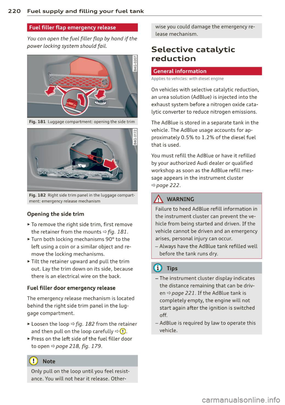
Fuel filler flap emergency release
You can open the fuel filler flap by hand if the
power locking system should fail .
Fig. 181 Luggage co m partmen t: open ing the side tr im
Fig. 182 Right side trim panel in the lu ggage compar t
ment: e mergency release mechanism
Opening the side trim
• To remove the right side trim, first remove
the retainer from the mounts
¢ fig. 181.
• Turn both locking mechanisms 90° to the
left using a coin or a similar object and re
move the locking mechanisms.
• Tilt the retainer upward and pull the trim
out . Lay the trim down on its side, because
there is an electrical wire on the back.
Fuel filler door emergency release
The emergency release mechanism is located
behind the right side trim panel in the lug
gage compartment.
• Loosen the loop i:>
fig. 182 from the retainer
and then pull on the loop carefully i:>Q).
• Press on the left side of the fuel filler door
to open
i=> page 218, fig. 179.
(D Note
Only pull on the loop until you feel resist
ance. You will not hear it release . Other- wise you could
damage the emergency re
l ease mechanism .
Selective catalytic
reduction
General information
Applies to vehicles: with diesel engine
On vehicles with selective cata lytic reduction,
an urea solution (Ad B lue) is injected into the
exhaust system before a nitrogen oxide cata
lytic converter to reduce nitrogen emissions.
The Ad Blue is stored in a separate tank in the
vehicle. The Ad Blue usage accounts for ap
proximately 0.5% to 1.2% of the diesel fuel
that is used.
You must refill the Ad Blue or have it refilled
by you r authorized Audi dea ler or qualified
workshop as soon as the Ad Blue refill mes
sage appears in the instrument cluster
¢page 222.
A WARNING
-Failure to heed AdBlue refill information in
the instrument cluster can prevent the ve
hicle from be ing started and driven . If the
vehicle cannot be driven and an emergency
arises, personal injury can occur.
- Always have the AdBlue tank refilled well
before the tank runs dry.
(D Tips
-The instrument cluster display ind icates
the distance remaining that can be driv
en
c> page 221. If the Ad Blue tank is
completely empty, the engine will not
start again after the ignition is switched
off.
-Ad Blue is required by law to operate this
vehicle.
Page 223 of 304
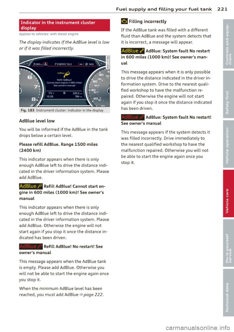
Indicator in the instrument cluster
display
Applies to vehicles: with diesel e ngine
The display indicates if the Ad Blu e level is low
or if it was filled incorre ctly.
Fig . 183 In strument clus te r: indica tor in th e display
AdBlue l evel low
You will be informed if the Ad Blue in the tank
drops be low a certain level.
Plea se refill Ad B lu e. Rang e 1500 miles
(2400 km)
This indicato r appears when there is on ly
enough Ad B lue left to drive the d istance ind i
cated in the driver i nformat ion system . Please
a dd AdB lue.
AdBlue ,0 Refill Ad Blue! Cannot start en
gine in
600 miles (1000 km )! See owner's
manual
This indicato r appears when there is only
e nough Ad B lue left to dr ive t he d istance ind i
cat ed in t he d rive r in format ion system . Please
add Ad Blue. O therw ise the eng ine will not
start ag ai n if you stop i t once the distan ce in
d icated has been driven.
Refill Ad Blue! No r estart! S ee
owner 's manual
This message appears when the AdBlue ta nk
i s empty . Please add Ad Blue. Otherwise you
will not be ab le to s tart th e engi ne aga in o nce
you stop i t.
W hen the minimum AdBlue level has been
reac hed, you must add Ad Bl ue
q page 222 .
Fuel suppl y and filli ng your fuel t ank 221
¢4 Filling incorrectly
If the AdBl ue tank was filled with a different
fluid than Ad B lue and the system dete cts t hat
it is incorrect, a message will appear.
AdBlue ./ AdBlue: Sy stem fault No restart
in
6 00 mile s (1000 km)! See owner 's man
ual
T his message appears w hen it is on ly possible
to dr ive the dis tance indicated in the d river in
format ion sys tem . Drive to the nea rest quali
fied wor kshop to have the ma lfunction re
paired. Otherwise the eng ine will not start
again if yo u stop it once the distance indicated
has been driven.
AdBlue: System fault No re start!
See owne r's manual
Th is message appears if the system detects it
was filled in co rrec tly. Drive immedia tely to
the nearest qua lified workshop to have the
malfu nction repaired . Otherwise yo u wi ll not
be able to start the engine again once you
stop it.
Page 224 of 304
222 Fuel supply and filling your fuel tank
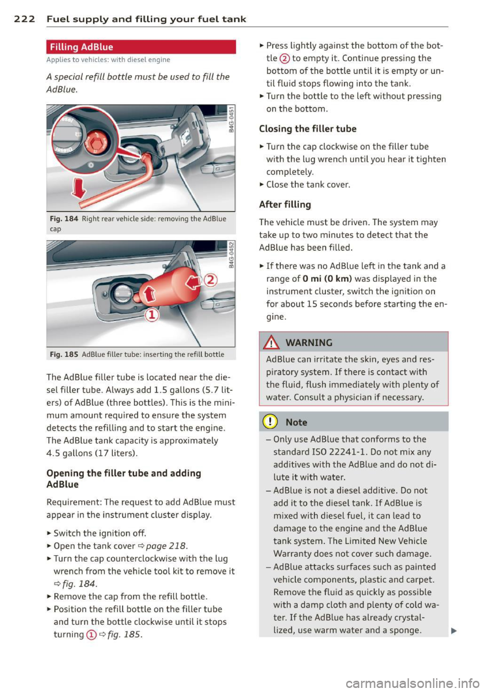
Filling AdBlue
Applies to vehicles: with diesel engine
A special refill bottle must be used to fill the
AdBlue .
Fig. 184 Rig ht rear vehicle side: remov ing the Ad B lue
cap
Fig . 185 Ad Blue filler tube: inse rting the refill bottle
The AdBlue fi ller tube is located near the die
sel filler tube . Always add 1.5 gallons (5. 7 lit
ers) of AdBlue (three bottles). This is the mini
mum amount required to ensure the system
detects the refilling and to start the eng ine.
The AdBlue tank capacity is approximately
4 .5 gal lons (17 liters).
Opening the filler tube and adding
AdBlue
Requirement : The request to add Ad Blue must
appear in the instrument cluster display.
• Switch the ignition off .
• Open the tank cover
¢page 218.
• Turn the cap counterclockw ise with the lug
wrench from the vehicle tool kit to remove it
¢fig. 184.
• Remove the cap from the refill bottle.
• Position the refill bottle on the filler tube
and turn the bottle clockwise until it stops
turning
(D ¢ fig . 185.
• Press lightly against the bottom of the bot
tle @to empty it. Continue pressing the
bottom of the bottle until it is empty or un
til fluid stops flowing into the tank.
• Turn the bottle to the left without pressing
on the bottom .
Closing the filler tube
• Turn the cap clockwise on the filler tube
with the lug wrench until you hear it tighten
completely .
• Close the tank cover.
After filling
The vehicle must be driven. The system may
take up to two minutes to detect that the
AdBlue has been f illed.
• If there was no Ad Blue left in the tank and a
range of
O mi (0 km) was displayed in the
instrument cluster, switch the ignition on
for about 15 seconds before starting the en gine.
A WARNING
= Ad Blue can irritate the sk in, eyes and res-
piratory system. If there is contact with
the fluid, flush immediately with plenty of
water. Consult a physician if necessary.
(D Note
- Only use Ad Blue that conforms to the
standard ISO 22241-1. Do not mix any
additives with the AdBlue and do not d i
lute it with water.
-A d Blue is not a diesel add itive . Do not
add it to the diesel tank. If Ad Blue is
m ixed with diesel fuel, it can lead to
damage to the engine and the AdBlue
tank system . The Limited New Vehicle
Warranty does not cover such damage.
- Ad Blue attacks surfaces such as painted
vehicle components, plastic and carpet.
Remove the fluid as quickly as possible
w ith a damp cloth and p lenty of cold wa
ter. If the AdBlue has already crystal-
lized, use warm water and a sponge. .,..
Page 231 of 304
(D Note
Driving with an insufficient oil level is like
ly to cause severe damage to the engine.
@ Tips
- The oil pre ssure w arning di spl ay . is
n ot an indi cato r of the oil le vel. D o not
rely on it. Inste ad , c heck th e oil le vel in
y ou r engine at regula r inter vals, pref
er ably each t ime you refu el, and al way s
befor e going on a long tr ip .
- If you have the impression your engine
consumes excessive amounts of oil, we
recommend that you consult your Audi
dealer to have the cause of yo ur conce rn
properly diagnosed. Keep in mind that
the accurate measurement of oil con
sump tion requires great care and may
take some time. Your Audi dealer has in
str uctions about how to measure oil con
sumption accurately.
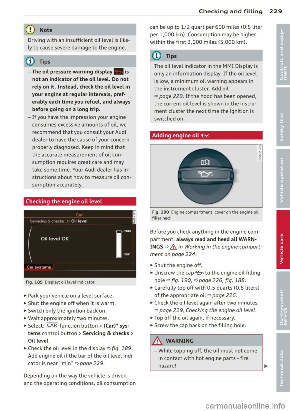
Checking the engine oil level
Fig. 18 9 Display: oil leve l indicato r
"'Park your vehicle on a level surface .
"' Shu t the engine off when it is warm.
"' Switch only the ignition back on.
"' Wait approximately two minutes.
"' Se lect :
I CARI funct ion button > ( Car )* sys -
tems
control button > Se rvicing & che ck s >
O il lev el.
"'Check the oil level in the display ¢fig. 189.
Add engine oil if the bar of the oil level indi
cator is near "min"
c::;,page 229 .
Depending on the way the veh icle is driven
and the operating conditions, oil consumption
Checkin g and fillin g 229
can be up to 1/2 quart pe r 600 miles (0.5 liter
per 1,000 km). Consumption may be higher
within the first 3,000 miles (5,000 km) .
(D Tips
The oil level indicator in the MMI Display is
on ly an information display. If the oil level
is low, a minimum oil warning appears in
the instrument cluster. Add oil
c::;, page 229. If the hood has been opened,
the current oil level is shown in the instru
ment cluster the next t ime the ignition is
switched on.
Adding engine oil~
Fig. 190 Eng in e compa rtm ent : cove r on the engine oi l
filler neck
Before you check anyth ing in the eng ine com
partment,
alw ays rea d and he ed all WARN
ING S
c::;, &. in Working in the engine compart
ment on page 224.
"' Shut the eng ine off .
"' Unscrew the cap
't".:::?: to the engine o il filling
hole
c::;, fig. 190, c::;, page 226, fig . 188.
"' Carefully top off with 0.5 quarts (0.5 liters)
of the appropriate oil
c::;, page 226.
"' Check the oil level again after two minutes
c::;, page 229, Checking the engine oil level.
"'Top off the oil again, if necessary.
"' Screw the cap back on the filling hole.
A WARNING
--Wh ile topping off, the o il must not come
in conta ct with hot engine parts -fi re
ha zard!
Page 261 of 304
remain continuously illuminated. This se
quence will continue upon subsequent vehicle
start-ups as long as the malfunction exists.
When the malfunction indicator is illuminat
ed, the system may not be able to detect or
signal low tire pressure as intended . TPMS
malfunctions may occur for a variety of rea
sons, including the installation of replace
ment or alternate tires or wheels on the vehi
cle that prevent the TPMS from functioning
properly . Always check the TPMS malfunction
telltale after replacing one or more tires or
wheels on your vehicle to ensure that the re
placement or alternate tires and wheels allow
the TPMS to continue to function properly.
Tire pressure indicator appears
Appl ies to vehicles: with tire pressur e monitoring sys te m
The tire pressure indicator in the instrument
cluster informs you if the tire pressure is too
low or if there is a system malfunction.
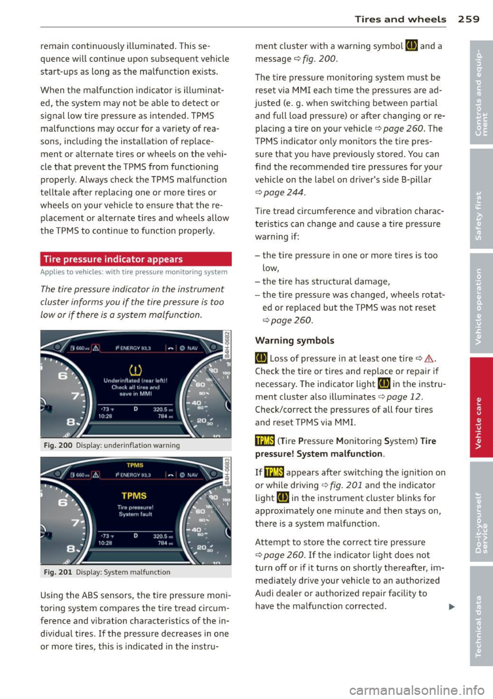
Fig. 200 Display : underinflation warning
Fig. 201 Display: System malfunction
Using the ABS sensors, the tire pressure moni
toring system compares the tire tread circum
ference and vibration characteristics of the in
dividual tires. If the pressure decreases in one
or more tires, this is indicated in the instru-
Tires and wheels 259
ment cluster with a warning symbol [I] and a
message
c::, fig. 200.
The tire pressure monitoring system must be
reset via MMI each time the pressures are ad
justed (e.g. when switching between partial
and full load pressure) or after changing or re
placing a tire on your vehicle
c::, page 260. The
TPMS indicator only monitors the tire pres
sure that you have previously stored. You can
find the recommended tire pressures for your
vehicle on the label on driver's side 8-pillar
~page 244.
Tire tread circumference and vibration charac
teristics can change and cause a tire pressure
warning if:
- the tire pressure in one or more tires is too
low,
- the tire has structural damage,
- the tire pressure was changed, wheels rotat-
ed or replaced but the TPMS was not reset
c::, page 260 .
Warning symbols
[I] Loss of pressure in at least one tire c::> &..
Check the tire or tires and replace or repair if
necessary. The indicator light
[I] in the instru
ment cluster also illuminates
c::>page 12.
Check/correct the pressures of all four tires
and reset TPMS via MMI.
i:mJ) (Tire Pressure Monitoring System) Tire
pressure! System malfunction .
If@m appears after switching the ignition on
or while driving
c::, fig. 201 and the indicator
light
[I] in the instrument cluster blinks for
approximately one minute and then stays on,
there is a system malfunction.
Attempt to store the correct tire pressure
c::, page 260. If the indicator light does not
turn off or if it turns on shortly thereafter, im
mediately drive your vehicle to an authorized
Audi dealer or authorized repair facility to
have the malfunction corrected.
Page 273 of 304
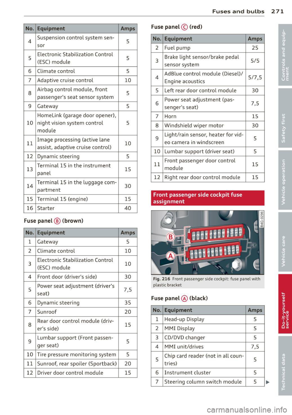
No. Equ ipment Amps
4 Suspension control system sen-s sor
s
E
lectronic Stabilization Cont rol
s (ESC) module
6 Climate control
5
7 Adaptive cruise control 10
8
Airbag control module, front
5
passenger 's seat sensor system
9 Gateway 5
Homelink (garage doo r opener),
10 night vis ion system cont ro l 5
module
11 Image
process ing (act ive lane
10
ass ist, adaptive cruise control)
12 Dynamic steering 5
13 Terminal 15 in
the instrument
15
panel
14 Terminal 15 in
the luggage com-
partment 30
15 Terminal 15 (eng
ine)
15
16 Starter 40
Fuse p anel ® (brown )
No . Equipment Amps
1 Gateway
5
2 C limate control 10
3 E
lectronic Stabili zation Contro l
10
(ESC) module
4 Fron
t door (driver 's side)
30
s
Power seat adjustment (driver's
7,5
seat)
6 Dynam
ic steering
35
7 Su nroof 20
8
Rear door control module (driv-
15
er 's side)
9 Lumbar support (
Front passen-
s ger seat)
10 Tire
pressure monitoring system
5
11 Su
nroof, rear spoi ler (Sport ba ck )
20
12 Driver door
control module
15
Fuse s and bulb s 2 71
Fuse panel © (red )
No . Equipment
2 Fuel pump
3 Brake lig
ht sensor/brake pedal
sensor system
AdBlue control module (Diesel)/
4 Engine acoustics
5 Left rear door cont rol modu le
6 Power seat adjustment
(pas-
senge r's seat)
7 Horn
8 Windshield wiper motor
9 Light/rain sensor, heater
for vid-
eo camera in windscreen
10 L umba r suppo rt (dr iver seat)
1 1 Front
passenger door control
modu le
1 2 Right rea r door cont rol mod ule
Front passenger side cockpit fuse
assignment Amp
s
25
5/5
5/7,S 30
7,5 15
30
s
5
15
15
F ig . 216 Front passenger side cockpit: f use panel w it h
plast ic brac ket
Fuse panel @ (blac k)
No . Equipment Amps
1 Head-up D
isplay
5
2 MMI Display 5
3 CO/DVD changer
5
4 MMI uni t/drives 7,5
5 Chip
card reader ( not in a ll coun -
5
tries)
6 Instrument
cluster
5
7 Steering col umn switch module 5 ...