key AUDI A8 2020 Owner's Manual
[x] Cancel search | Manufacturer: AUDI, Model Year: 2020, Model line: A8, Model: AUDI A8 2020Pages: 360, PDF Size: 95.38 MB
Page 59 of 360
4N0012721BD
Opening and closing
> Lock the glove compartment with the mechani-
cal key.
> Give your vehicle key to the service personnel
who are parking your vehicle and keep the me-
chanical key.
The following buttons are deactivated when the
valet parking function is switched on:
— <3 button in the driver's door
— <3 or 4s button on the vehicle key
— Handle in the luggage compartment lid
If the valet parking function is switched on, a
message will appear every time the ignition is
switched on.
@ Tips
Please note that the luggage compartment
can still be accessed from the vehicle interior
in vehicles with fixed rear seat backrests or
ones that cannot be locked, even when the
valet parking function is switched on.
Garage door opener
Applies to: vehicles with garage door opener
2 + S >
<
go EI
ent systems
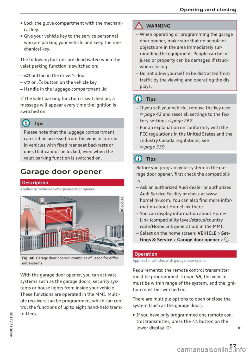
With the garage door opener, you can activate
systems such as the garage doors, security sys-
tems or house lights from inside your vehicle.
These functions are operated in the MMI. Multi-
ple receivers can be programmed, which can con-
trol the functions of up to eight hand-held trans-
mitters.
ZX WARNING
— When operating or programming the garage
door opener, make sure that no people or
objects are in the area immediately sur-
rounding the equipment. People can be in-
jured or property can be damaged if struck
when closing.
— Do not allow yourself to be distracted from
traffic by the viewing and operating the dis-
plays.
G) Tips
— If you sell your vehicle, remove the key user
= page 42 and reset all settings to the fac-
tory settings > page 267.
— For an explanation on conformity with the
FCC regulations in the United States and the
Industry Canada regulations, see
> page 339.
G) Tips
Before you program your system to the ga-
rage door opener, first check the compatibili-
ty:
— Ask an authorized Audi dealer or authorized
Audi Service Facility or check at www.
homelink.com. You can also find more infor-
mation about HomeLink there.
— You can display information about Home-
Link (compatibility level/status/country
code/HomeLink generation) in the MMI:
— Select on the home screen: VEHICLE > Set-
tings & Service > Garage door opener > @.
Applies to: vehicles with garage door opener
Requirements: the remote control transmitter
must be programmed > page 58, the vehicle
must be within range of the system, and the igni-
tion must be switched on.
There are multiple options to open or close the
system (such as the garage door).
> If you have only programmed one remote con-
trol transmitter, press the ra button on the
lower
display. Or
57
Page 84 of 360

Sitting correctly and safely
Adjusting the outer head restraints
Applies to: vehicles with manual head restraints
> To adjust the head restraint upward, slide it un-
til it locks into place.
> To adjust the head restraint downward, press
the button @) and slide the head restraint. Re-
lease the button and slide the head restraint
farther until it locks into place.
Applies to: vehicles with power head restraints
> To adjust the head restraint upward or down-
ward, push the button 2) > page 76, fig. 64
forward or backward. Or:
> Applies to: Rear Seat Remote: To adjust the
head restraint upward or downward: select on
the home screen: Seats > Setting and press on
the picture of the head restraint for the respec-
tive seat. Press the up or down arrows until the
desired position is reached.
Adjusting the center head restraint
> Fold the head restraint upward until it clicks in-
to place > fig. 72.
> To fold the head restraint downward, press the
button on the back of the head restraint.
Removing the headrests
Applies to: vehicles with removable head restraints
> Move the head restraint upward all the way.
> Insert a suitable object, such as the the extend-
ed vehicle key or mechanical key, into the re-
lease point @ on the inside or outside of the
base.
> Press the button @) and pull the head restraint
out of the backrest > A\ in General informa-
tion on page 81.
Installing the headrests
Applies to: vehicles with removable head restraints
> Slide the posts on the head restraint down into
the guides until the posts click into place.
> Press the button @) and slide the head restraint
all the way down. It should not be possible to
remove the head restraint from the backrest
without pressing the button.
82
Safety belts
General information
Each seat is equipped with a three-point safety
belt. Safety belts that are worn correctly are the
most effective way to reduce the risk of serious or
fatal injuries in a collision. Therefore, wear your
safety belt correctly and make sure that all vehi-
cle passengers are also wearing their safety belts
correctly when the vehicle is moving.
Even though your vehicle is equipped with an air-
bag system, every vehicle passenger must still al-
ways wear the appropriate safety belt. In addi-
tion to their normal protective function, safety
belts also hold vehicle occupants in the correct
seating position in the event of a collision so that
the
airbags can deploy correctly and provide addi-
tional protection. Safety belts provide protection
during collisions when the airbags do not deploy
or if they have already deployed.
ZX WARNING
The risk of serious or fatal injury increases if
the safety belt is not fastened, if it is worn in-
correctly, or if it is damaged.
— All vehicle occupants, including the driver,
must fasten their safety belts correctly be-
fore every trip and must always keep their
safety belts fastened during the trip, regard-
less of whether the seat is equipped with an
airbag or not. This also applies to children
that are seated in a child safety seat that is
appropriate for their weight and age and
that is secured with a safety belt.
— In the event of a collision, vehicle occupants
that are not wearing safety belts could be
propelled through the vehicle interior and
collide with vehicle components, such as the
steering wheel, instrument panel, wind-
shield, or doors. In some situations, vehicle
occupants could also be ejected from the ve-
hicle. Vehicle occupants in the rear seats
who do not wear safety belts not only en-
danger themselves, but also other people in
the vehicle.
— Only one person may be fastened with a
safety belt at a time. Never secure more
Page 99 of 360
4N0012721BD
Stowing and using
Stowing and using
Power sources
When the ignition is switched on, you may be
able to use multiple power sources for external
devices, depending on the vehicle equipment.
12 volt sockets
You can connect electrical accessories to the 12
volt sockets. The power usage must not exceed
120 watts.
The 12 volt sockets are labeled with the 12V
symbol. They are located in the front center con-
sole, in the rear* and on the side trim panel in the
luggage compartment*.
USB ports
Applies to: vehicles with USB port
You can charge mobile devices using the USB
ports. The USB ports are labeled with the «<> or
(4 symbol or CHARGE ONLY.
115 volt socket
Applies to: vehicles with 115 volt socket
The socket is located in the center console in the
rear and can be used for electrical devices > A\.
The power usage must not exceed 150 watts.
When you push the device connector all the way
into the socket, the child safety mechanism re-
leases and there is electric current.
—If the LED on the socket is green or flashes
slowly, then the socket is ready for use.
—If the LED is red and flashes quickly, there is a
malfunction in the connected device or the
socket is too hot. The socket will switch off for
safety reasons. To reactivate the socket, remove
the device connector. Connect the device after
correcting the malfunction or reconnect after a
brief cool-down period.
— Incorrect usage can lead to serious injuries
or burns. To reduce the risk of injuries, never
leave children unattended in the vehicle
with the key.
Z\ WARNING
Applies to: vehicles with 115 volt socket
—To reduce the risk of fatal injury, do not in-
sert any conductive objects, such as knitting
needles, into the contacts on the socket.
—To reduce the risk of fatal injury, do not spill
any fluids on the socket. Should any mois-
ture enter the socket, make sure that it has
dried out completely before using the socket
again.
— If devices or connectors that are heavy (such
as a power supply unit) are attached directly
to the socket, the holder can become dam-
aged, which increases the risk of injury.
— Using adapters and extension cables in-
creases the risk of injury because they over-
ride the safety devices for the socket.
—To reduce the risk of injury, remove the con-
nector of the connected device if the socket
has switched off due to a malfunction.
Z\ WARNING
—To reduce the risk of fatal injury, store all
connected devices securely when driving so
that they do not move around inside the ve-
hicle when braking or in the event of an acci-
dent.
@) Note
— Read the operating manuals for the con-
nected devices.
—To reduce the risk of damage to the vehicle
electrical system, never attempt to charge
the vehicle battery by connecting accesso-
ries that provide power to the power sour-
ces.
— Do not connect any device whose network
class (voltage) does not match the network
class designed for the socket.
— Disconnect the connectors from the power
sources carefully to reduce the risk of dam-
aging them.
(i) Tips
Applies to: vehicles with 115 volt socket
— Devices that are not shielded or devices near
the rear window antenna can cause mal-
functions in the radio, TV, or vehicle electri-
cal system.
97
Page 101 of 360
4N0012721BD
Stowing and using
Folding tray tables
Applies to: vehicles with folding tray tables
Fig. 88 Rear center console: extending and adjusting the
folding tray table
Folding up and down
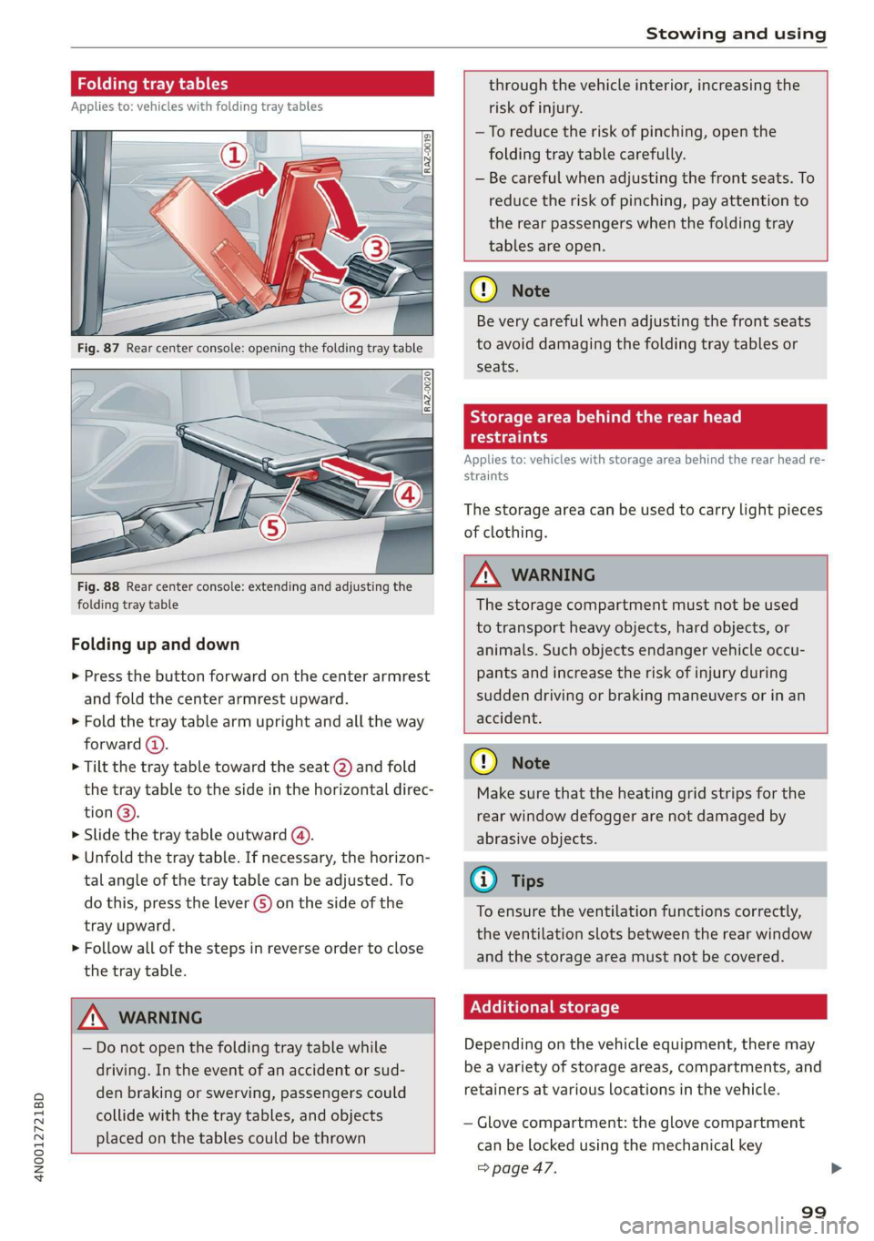
> Press the button forward on the center armrest
and fold the center armrest upward.
> Fold the tray table arm upright and all the way
forward (4).
> Tilt the tray table toward the seat (2) and fold
the tray table to the side in the horizontal direc-
tion @).
> Slide the tray table outward (4).
>» Unfold the tray table. If necessary, the horizon-
tal angle of the tray table can be adjusted. To
do this, press the lever G) on the side of the
tray upward.
> Follow all of the steps in reverse order to close
the tray table.
ZA WARNING
— Do not open the folding tray table while
driving. In the event of an accident or sud-
den braking or swerving, passengers could
collide with the tray tables, and objects
placed on the tables could be thrown
through the vehicle interior, increasing the
risk of injury.
—To reduce the risk of pinching, open the
folding tray table carefully.
— Be careful when adjusting the front seats. To
reduce the risk of pinching, pay attention to
the rear passengers when the folding tray
tables are open.
() Note
Be very careful when adjusting the front seats
to avoid damaging the folding tray tables or
seats.
Storage area behind the rear head
oe)
Applies to: vehicles with storage area behind the rear head re-
straints
The storage area can be used to carry light pieces
of clothing.
ZA WARNING
The storage compartment must not be used
to transport heavy objects, hard objects, or
animals. Such objects endanger vehicle occu-
pants and increase the risk of injury during
sudden driving or braking maneuvers or in an
accident.
@) Note
Make sure that the heating grid strips for the
rear window defogger are not damaged by
abrasive objects.
@ Tips
To ensure the ventilation functions correctly,
the ventilation slots between the rear window
and the storage area must not be covered.
Nellie etl lel
Depending on the vehicle equipment, there may
be a variety of storage areas, compartments, and
retainers at various locations in the vehicle.
— Glove compartment: the glove compartment
can be locked using the mechanical key
=> page 47.
99
Page 113 of 360
4N0012721BD
Driving
Driving
Starting the vehicle
Dye Tod f ola (ela)
Fig. 97 Center console: starting the engine
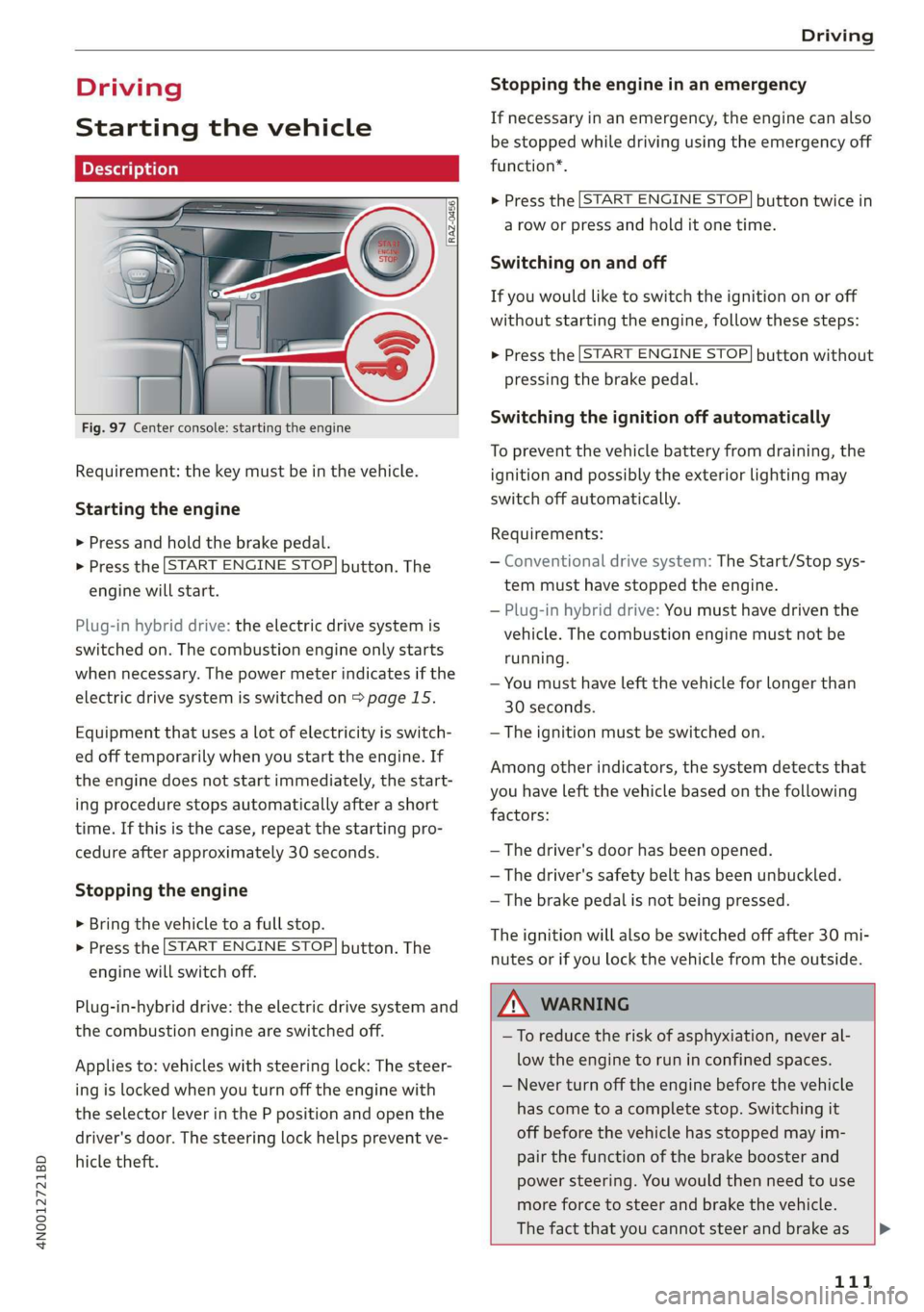
Requirement: the key must be in the vehicle.
Starting the engine
> Press and hold the brake pedal.
> Press the [START ENGINE STOP] button. The
engine will start.
Plug-in hybrid drive: the electric drive system is
switched on. The combustion engine only starts
when necessary. The power meter indicates if the
electric drive system is switched on > page 15.
Equipment that uses a lot of electricity is switch-
ed off temporarily when you start the engine. If
the engine does not start immediately, the start-
ing procedure stops automatically after a short
time. If this is the case, repeat the starting pro-
cedure after approximately 30 seconds.
Stopping the engine
> Bring the vehicle to a full stop.
> Press the [START ENGINE STOP] button. The
engine will switch off.
Plug-in-hybrid drive: the electric drive system and
the combustion engine are switched off.
Applies to: vehicles with steering lock: The steer-
ing is locked when you turn off the engine with
the selector lever in the P position and open the
driver's door. The steering lock helps prevent ve-
hicle theft.
Stopping the engine in an emergency
If necessary in an emergency, the engine can also
be stopped while driving using the emergency off
function*.
> Press the [START ENGINE STOP] button twice in
a row or press and hold it one time.
Switching on and off
If you would like to switch the ignition on or off
without starting the engine, follow these steps:
> Press the [START ENGINE STOP] button without
pressing the brake pedal.
Switching the ignition off automatically
To prevent the vehicle battery from draining, the
ignition and possibly the exterior lighting may
switch off automatically.
Requirements:
— Conventional drive system: The Start/Stop sys-
tem must have stopped the engine.
— Plug-in hybrid drive: You must have driven the
vehicle. The combustion engine must not be
running.
— You must have left the vehicle for longer than
30 seconds.
— The ignition must be switched on.
Among other indicators, the system detects that
you have left the vehicle based on the following
factors:
— The driver's door has been opened.
— The driver's safety belt has been unbuckled.
— The brake pedal is not being pressed.
The ignition will also be switched off after 30 mi-
nutes or if you lock the vehicle from the outside.
ZA WARNING
—To reduce the risk of asphyxiation, never al-
low the engine to run in confined spaces.
— Never turn off the engine before the vehicle
has come to a complete stop. Switching it
off before the vehicle has stopped may im-
pair the function of the brake booster and
power steering. You would then need to use
more force to steer and brake the vehicle.
The fact that you cannot steer and brake as |P>
111
Page 114 of 360
Driving
usual may increase the risk of accidents and
serious injuries.
— Always select the “P” selector lever position
when parking the vehicle; otherwise, the ve-
hicle could roll away.
C) Note
— Avoid high engine speed, full throttle, and
heavy engine load if the engine has not
reached operating temperature yet. You
could damage the engine.
— If the engine has been under heavy load for
an extended period of time, heat builds up
in the engine compartment after the engine
is switched off and there is a risk of damag-
ing the engine. For this reason, let the en-
gine run at idle for approximately two mi-
nutes before shutting it off.
G) Tips
— Brief noises are normal when starting and
stopping the vehicle and are no cause for
concern.
— For up to 10 minutes after stopping the en-
gine, the radiator fan may turn on again au-
tomatically or it may continue to run, even if
the ignition is switched off.
— It may not be possible to start the vehicle in
extremely low temperatures.
— Power will be fully available once the engine
is at operating temperature.
= Engine start system: malfunction! Please
contact Service
Do not switch the ignition off because you may
not be able to switch it on again. Drive to an au-
thorized Audi dealer or authorized Audi Service
Facility immediately to have the malfunction cor-
rected.
|| Engine start system: malfunction! Please
contact Service
There is a malfunction in the engine start system.
Drive immediately to an authorized Audi dealer
112
or authorized Audi Service Facility to have the
malfunction repaired.
B Remote control key: key not detected. Is the
key
still in the vehicle?
The vehicle key was removed from the vehicle
while the engine is running. If the vehicle key is
no longer in the vehicle, you cannot switch the ig-
nition on or start the engine once you stop it. You
also cannot lock the vehicle from the outside.
Remote control key: hold back of key
against the designated area. See owner's man-
ual
The battery in the vehicle key may be drained or
there may be a malfunction. To start the vehicle,
you must also hold the vehicle key against the lo-
cation shown ?) & page 111, fig. 97.
If the malfunction remains, drive immediately to
an authorized Audi dealer or authorized Audi
Service Facility to have the malfunction correct-
ed.
When driving
Starting to drive, stopping, and parking
Starting from a stop
> Press and hold the brake pedal.
> Start the engine.
> Select a gear.
> Release the parking brake.
> Release the brake pedal. The vehicle may roll.
> Press the accelerator pedal to accelerate.
Stopping and parking
> Bring the vehicle to a full stop and press and
hold the brake pedal.
> Set the parking brake.
> Select the “P” selector lever position to secure
the vehicle from rolling away.
> Turn the steering wheel when parking on in-
clines so that the wheels will roll into the curb
if the vehicle starts moving.
> Switch off the ignition before leaving the vehi-
cle.
On hills, activate the parking brake first and then
shift into the "P" selector lever position. This >
Page 115 of 360

4N0012721BD
Driving
prevents too much stress from being placed on
the locking mechanism.
ZA\ WARNING
— Always set the parking brake when leaving
your vehicle, even if for a short period of
time. If the parking brake is not set, the ve-
hicle could roll away, increasing the risk of
an accident.
— Do not leave your vehicle unattended while
the engine is running, because this increases
the risk of an accident.
— If the parking brake is set, it can release au-
tomatically when the accelerator pedal is
pressed. To reduce the risk of an accident,
do not inadvertently press the accelerator
pedal and always shift into “P” when the ve-
hicle is stopped.
— If you leave the vehicle, switch the ignition
off and take the key with you. This is espe-
cially important when leaving persons or an-
imals in the vehicle. Otherwise, the vehicle
could start unintentionally, the parking
brake could release, or electronic equipment
could activate, which increases the risk of an
accident.
— No persons or animals should be left in a
locked vehicle. Locked doors make it more
difficult for emergency workers to enter the
vehicle, which puts lives at risk.
— If you do not begin driving immediately af-
ter releasing the brake pedal, your vehicle
may begin to roll backward. Press the brake
pedal or set the parking brake immediately.
@) Note
If you have to stop on an incline, always press
the brake pedal to hold the vehicle in place to
reduce the risk of the vehicle rolling back-
ward. Do not try to hold the vehicle in place
by pressing and holding the accelerator pedal.
The transmission can overheat, which increas-
es the risk of damage.
Hill hold assist
If you take your foot off of the brake pedal when
driving on hills, the braking force will be held for
several seconds. At that time, you can start driv-
ing without the vehicle rolling backward.
Requirement: the driver's door must be closed,
the engine must be on, and the vehicle must be
traveling uphill.
> To activate hill hold assist, press and hold the
brake pedal for several seconds while the vehi-
cle is stationary.
Z\ WARNING
— If you do not begin driving immediately af-
ter releasing the brake pedal, your vehicle
may begin to roll backward. Press the brake
pedal or set the parking brake immediately.
— The hill hold assist cannot hold the vehicle
on inclines in every scenario (for example,
on slippery or icy ground).
Messages
Take over!
The vehicle cannot be held in place automatically.
Press the brake pedal to secure the vehicle from
rolling away unintentionally.
Gears and driving programs
Oo
@—*
RAZ-0410:
R
N
tt
D/S
7 NEI
Fig. 98 Center console: selector lever
The automatic transmission shifts automatically
depending on the selected gear and the current
driving style. When driving with a moderate driv-
ing style, upshifting early and downshifting late
will help to improve fuel economy. When driving
with a sporty driving style, the transmission per-
mits higher RPMs.
The gears are displayed next to the selector lever. >
113
Page 130 of 360
Driving dynamic
Driving dynamic
Audi drive select
Introduction
Applies to: vehicles with Audi drive select
Drive select makes it possible to experience dif
ferent types of vehicle characteristics in one vehi-
cle. With different driving modes, the driver can
switch the setting, for example from sporty to
comfortable. This allows you to adjust the set-
tings to your personal preferences. This makes it
possible to combine settings such as a sporty
drivetrain setting with comfortable steering.
Selecting an Audi drive select mode
Applies to: vehicles with Audi drive select
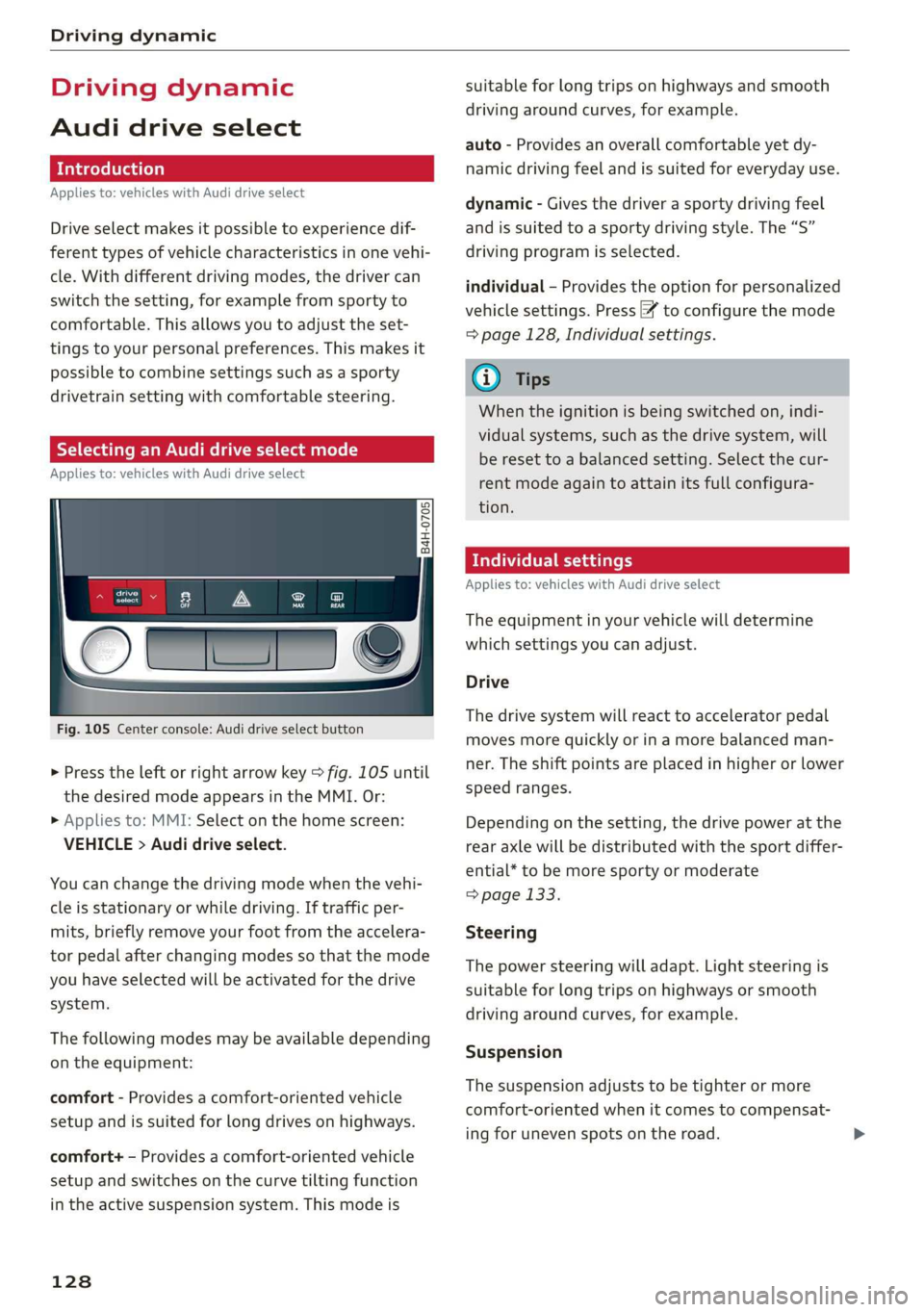
Fig. 105 Center console: Audi drive select button
> Press the left or right arrow key > fig. 105 until
the desired mode appears in the MMI. Or:
» Applies to: MMI: Select on the home screen:
VEHICLE > Audi drive select.
You can change the driving mode when the vehi-
cle is stationary or while driving. If traffic per-
mits, briefly remove your foot from the accelera-
tor pedal after changing modes so that the mode
you have selected will be activated for the drive
system.
The following modes may be available depending
on the equipment:
comfort - Provides a comfort-oriented vehicle
setup and is suited for long drives on highways.
comfort+ - Provides a comfort-oriented vehicle
setup and switches on the curve tilting function
in the active suspension system. This mode is
128
suitable for long trips on highways and smooth
driving around curves, for example.
auto - Provides an overall comfortable yet dy-
namic driving feel and is suited for everyday use.
dynamic - Gives the driver a sporty driving feel
and is suited to a sporty driving style. The “S”
driving program is selected.
individual - Provides the option for personalized
vehicle settings. Press [7 to configure the mode
= page 128, Individual settings.
(i) Tips
When the ignition is being switched on, indi-
vidual systems, such as the drive system, will
be reset to a balanced setting. Select the cur-
rent mode again to attain its full configura-
tion.
Individual settings
Applies to: vehicles with Audi drive select
The equipment in your vehicle will determine
which settings you can adjust.
Drive
The drive system will react to accelerator pedal
moves more quickly or in a more balanced man-
ner. The shift points are placed in higher or lower
speed ranges.
Depending on the setting, the drive power at the
rear axle will be distributed with the sport differ-
ential* to be more sporty or moderate
> page 133.
Steering
The power steering will adapt. Light steering is
suitable for long trips on highways or smooth
driving around curves, for example.
Suspension
The suspension adjusts to be tighter or more
comfort-oriented when it comes to compensat-
ing for uneven spots on the road.
Page 142 of 360
High-voltage system
the possible charging display colors under
=> page 140.
The charging connector is locked while charging
and cannot be removed.
If the driver's door is opened while the ignition is
switched off, the current battery charge level and
the high-voltage battery range will be displayed
in the instrument cluster. If charging is in prog-
ress, the remaining charging time will also be
displayed.
Immediate charging and timer charging
You can switch between the immediate charging
@ and charging timer @ options during the
charging process if a charging timer is set
= page 141. Press the desired button to do this.
Ending the charging process
You can interrupt the charging process at any
time.
— Unlock the vehicle or press the @/(@) button
when the vehicle is unlocked, and the LED will
turn on.
— Remove the charging connector. If the charging
connector is not removed within 30 seconds, it
will automatically relock and the charging proc-
ess may continue.
— Put the cap back on the charging port.
— Close the charging port door.
— Disconnect the charging cable from the power
supply if necessary or return it securely to the
charging station.
— Install the protective caps on the charging ca-
ble again.
— If you are transporting the charging cable in
the vehicle, store it securely > page 144.
If the charging connector cannot be removed,
you must unlock it manually > page 142.
ZA\ WARNING
— Do not disconnect the charging cable from
the socket or the vehicle charging port while
the vehicle is charging. End the charging
process before removing the charging cable
from the socket in order to reduce the risk of
damaging the connector contacts from
sparks.
—If the charging unit is damaged, do not
charge using the charging port to reduce the
risk of injury.
— If the charging unit is damaged or the
charging port door cannot close or is miss-
ing, drive immediately to an authorized Audi
dealer or authorized Audi Service Facility
and have the malfunction corrected to re-
duce the risk of injury.
() Note
If you drive with the charging unit open, both
the charging port door and the electronics in-
stalled behind it could be damaged. Check
each time after charging if the port door is
locked before you start driving the vehicle.
@) Tips
— If the parking brake is set, it could create
noises when the charging connector is con-
nected.
— Remove ice and snow in the charging unit
using a hand brush and solvent-free deicing
spray.
— The vehicle radio and TV systems may have
limited reception when charging the vehicle.
Charging display
Applies to: vehicles with plug-in hybrid drive
The charging display is an LED light on the charg-
ing unit @) > page 139, fig. 107 that indicates
the charging status. The key for the LED light is
explained in the following table.
LED on the charging unit Meaning
Vehicle charging system is in sleep mode. A timer may be active,
Off but charging has not started yet.
Charging process is interrupted. >
140
Page 152 of 360
High-voltage system
> Close the lever @) until it is resting on the con-
nector (2).
> Remove the connector (2) completely.
Attaching the cable
> Lift the lever @ up slightly.
> Insert the connector (2) into the control unit
just until you feel resistance.
> Lift the lever @ all the way up.
> Insert the connector (2) all the way into the
control unit.
> Close the lever ().
> Tighten the screw (3) using the screwdriver pro-
vided.
Z\ WARNING
— Note the warnings for charging > A\ in
Charging on page 140.
— Before switching a cable, always unplug the
power cable from the socket.
— Only change cables in a dry environment.
— The Audi charging system may only be used
as a complete unit consisting of the power
cables, the control unit, and the vehicle ca-
ble. Depending on the country, the total
length of the power cable, control panel and
vehicle cable may be restricted, for example
to 24.6 ft (7.5 m) in the USA. We recom-
mend using only cables approved by Audi.
G) Tips
The power cable with the power connector for
industrial sockets and the Audi charging sys-
tem control unit are designed to work togeth-
er. Changing the power cable to another con-
nector type may reduce the available charging
power of the entire system.
150
Wall mount clip
Applies to: vehicles with plug-in hybrid drive and wall mount
clip
[RAZ-0638|
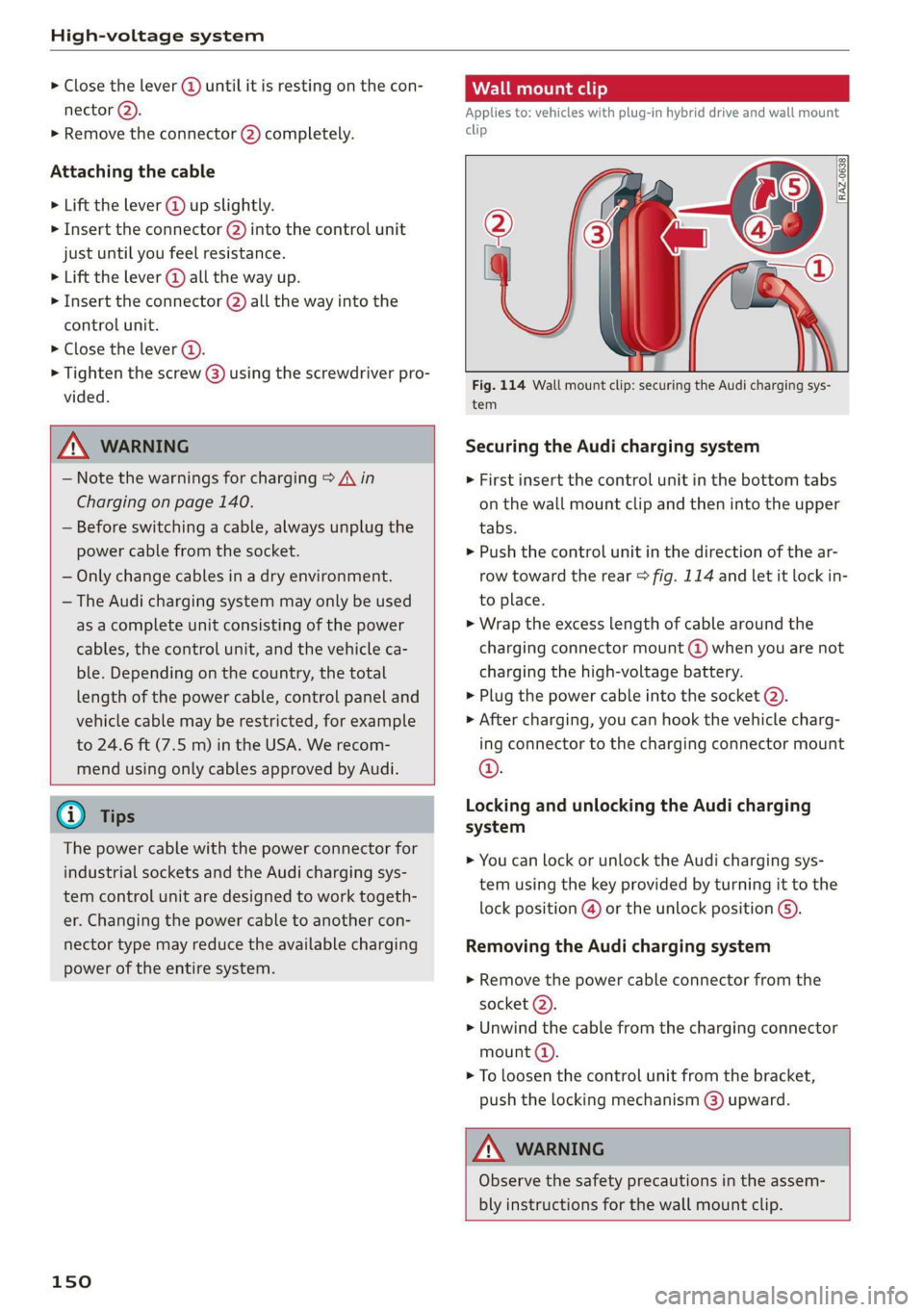
Fig. 114 Wall mount clip: securing the Audi charging sys-
tem
Securing the Audi charging system
> First insert the control unit in the bottom tabs
on the wall mount clip and then into the upper
tabs.
» Push the control unit in the direction of the ar-
row toward the rear > fig. 114 and let it lock in-
to place.
> Wrap the excess length of cable around the
charging connector mount @) when you are not
charging the high-voltage battery.
> Plug the power cable into the socket (2).
» After charging, you can hook the vehicle charg-
ing connector to the charging connector mount
©.
Locking and unlocking the Audi charging
system
> You can lock or unlock the Audi charging sys-
tem using the key provided by turning it to the
lock position @) or the unlock position @).
Removing the Audi charging system
> Remove the power cable connector from the
socket @).
> Unwind the cable from the charging connector
mount (a).
> To loosen the control unit from the bracket,
push the locking mechanism @) upward.
ZA\ WARNING
Observe the safety precautions in the assem-
bly instructions for the wall mount clip.