diagram AUDI Q3 2019 Owners Manual
[x] Cancel search | Manufacturer: AUDI, Model Year: 2019, Model line: Q3, Model: AUDI Q3 2019Pages: 280, PDF Size: 72.73 MB
Page 21 of 280
83A012721BA
Touch display
Menus and symbols
ee) Pe Sian Ics}
Maat recs
RAX-0103,
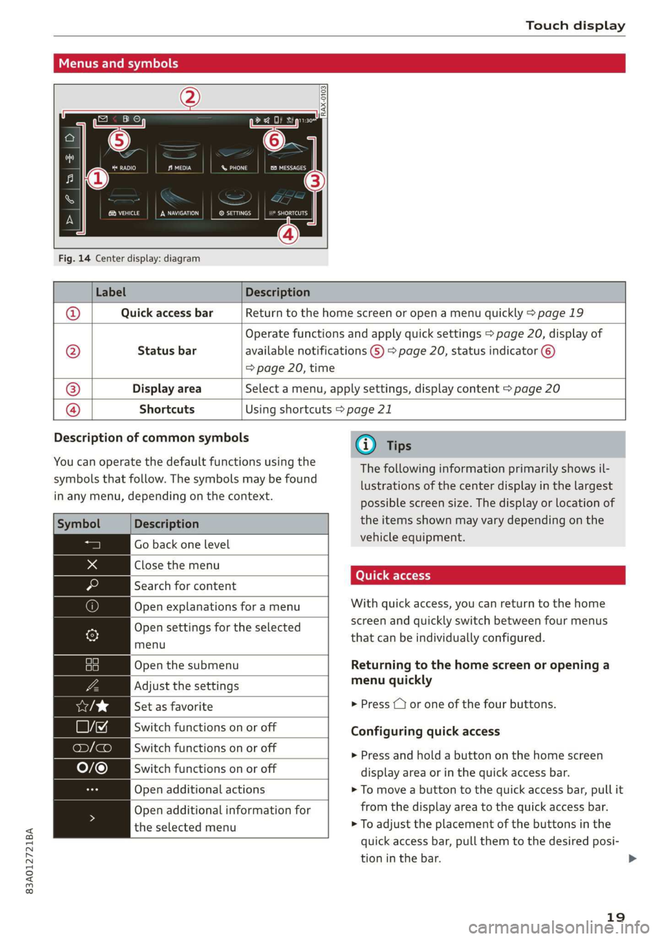
Fig. 14 Center display: diagram
Label Description
Quick access bar Return to the home screen or open a menu quickly > page 19
Status bar
Operate functions and apply quick settings > page 20, display of
available notifications G) > page 20, status indicator ©)
=> page 20, time
Display area Select a menu, apply settings, display content > page 20
®|O,
©
|O
Shortcuts Using shortcuts > page 21
Description of common symbols
You can operate the default functions using the
symbols that follow. The symbols may be found
in any menu, depending on the context.
Description
Close the menu
Search for content
menu
Open the submenu
Set as favorite
Switch functions on or off
Open additional actions
the selected menu
Go back one level
Open explanations for a menu
Open settings for the selected
Adjust the settings
Switch functions on or off
Switch functions on or off
Open additional information for
@) Tips
The following information primarily shows il-
lustrations of the center display in the largest
possible screen size. The display or location of
the items shown may vary depending on the
vehicle equipment.
With quick access, you can return to the home
screen and quickly switch between four menus
that can be individually configured.
Returning to the home screen or opening a
menu quickly
> Press ( or one of the four buttons.
Configuring quick access
» Press and hold a button on the home screen
display area or in the quick access bar.
> To move a button to the quick access bar, pull it
from the display area to the quick access bar.
> To adjust the placement of the buttons in the
quick access bar, pull them to the desired posi-
tion in the bar.
19
>
Page 22 of 280
Touch display
@) Tips
The position of © cannot be adjusted.
Display area
You can freely change the location of the buttons
on the home screen display area.
Configuring the display area
> Press and hold a button on the home screen
display area.
> To adjust the placement of the buttons, pull
them to the desired locations.
Switching between menu pages
If a menu contains multiple menu pages, Feit is
displayed in the display area. The white bar
shows the location of the current menu page.
> To switch between menu pages, swipe your fin-
ger to the right or left.
yeh mele) EN]
Of 8 68 of
8 OB OB om
[RAZ-0513,
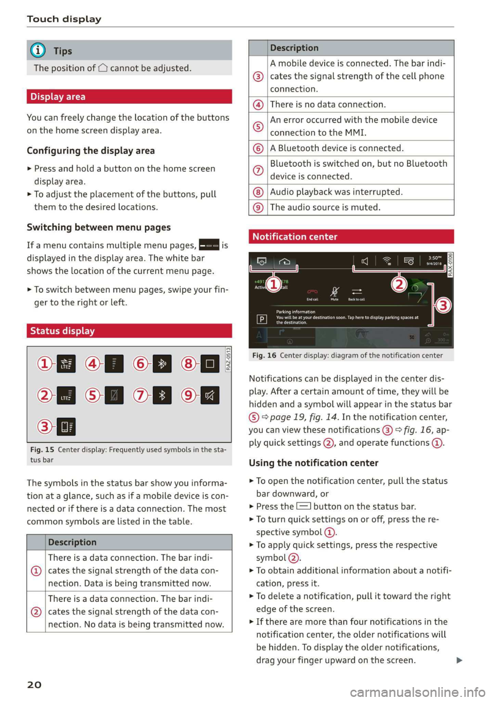
Fig. 15 Center display: Frequently used symbols in the sta-
tus bar
The symbols in the status bar show you informa-
tion at a glance, such as if a mobile device is con-
nected or if there is a data connection. The most
common symbols are listed in the table.
Description
There is a data connection. The bar indi-
@ | cates the signal strength of the data con-
nection. Data is being transmitted now.
There is a data connection. The bar indi-
@ | cates the signal strength of the data con-
nection. No data is being transmitted now.
20
Description
A mobile device is connected. The bar indi-
cates the signal strength of the cell phone
connection.
There is no data connection.
An error occurred with the mobile device
connection to the MMI.
A Bluetooth device is connected.
Bluetooth is switched on, but no Bluetooth
device is connected.
Audio playback was interrupted.
©O|©|
© |E|
©
|@|
@
The audio source is muted.
Notification center
RAX-0106
Parking information
aeons
Regier
Fig. 16 Center display: diagram of the notification center
Notifications can be displayed in the center dis-
play. After a certain amount of time, they will be
hidden and a symbol will appear in the status bar
® page 19, fig. 14. In the notification center,
you can view these notifications @) > fig. 16, ap-
ply quick settings (2), and operate functions @.
Using the notification center
> To open the notification center, pull the status
bar downward, or
> Press the E=] button on the status bar.
> To turn quick settings on or off, press the re-
spective symbol ().
> To apply quick settings, press the respective
symbol (2).
> To obtain additional information about a notifi-
cation, press it.
> To delete a notification, pull it toward the right
edge of the screen.
> If there are more than four notifications in the
notification center, the older notifications will
be hidden. To display the older notifications,
drag your finger upward on the screen.
Page 24 of 280
Touch display
acalileltia
pee
les
ae
Downtown
Coa
Downtown
Los Angeles, W
Pea)
> oo
RAZ-0700!
J John Smith ©)
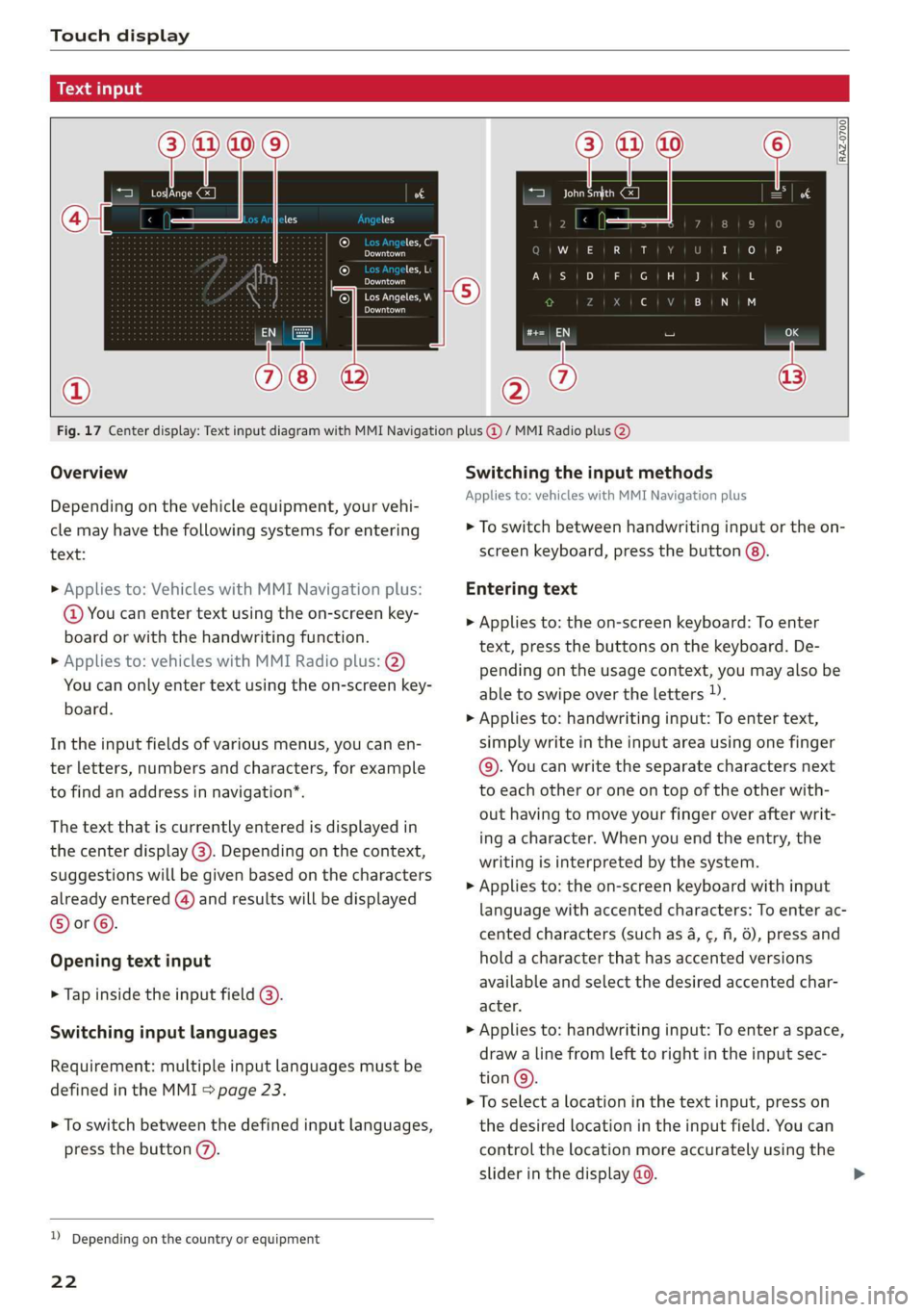
Fig. 17 Center display: Text input diagram with MMI Navigation plus @ / MMI Radio plus @)
Overview
Depending on the vehicle equipment, your vehi-
cle may have the following systems for entering
text:
> Applies to: Vehicles with MMI Navigation plus:
@ You can enter text using the on-screen key-
board or with the handwriting function.
> Applies to: vehicles with MMI Radio plus: @)
You can only enter text using the on-screen key-
board.
In the input fields of various menus, you can en-
ter letters, numbers and characters, for example
to find an address in navigation’.
The text that is currently entered is displayed in
the center display @). Depending on the context,
suggestions will be given based on the characters
already entered () and results will be displayed
®or©.
Opening text input
> Tap inside the input field @).
Switching input languages
Requirement: multiple input languages must be
defined in the MMI > page 23.
> To switch between the defined input languages,
press the button (7).
) Depending on the country or equipment
22
Switching the input methods
Applies to: vehicles with MMI Navigation plus
> To switch between handwriting input or the on-
screen keyboard, press the button (8).
Entering text
> Applies to: the on-screen keyboard: To enter
text, press the buttons on the keyboard. De-
pending on the usage context, you may also be
able to swipe over the letters )).
> Applies to: handwriting input: To enter text,
simply write in the input area using one finger
©. You can write the separate characters next
to each other or one on top of the other with-
out having to move your finger over after writ-
ing a character. When you end the entry, the
writing is interpreted by the system.
> Applies to: the on-screen keyboard with input
language with accented characters: To enter ac-
cented characters (such as 4, ¢, fi, 6), press and
hold a character that has accented versions
available and select the desired accented char-
acter.
> Applies to: handwriting input: To enter a space,
draw a line from left to right in the input sec-
tion@.
> To select a location in the text input, press on
the desired location in the input field. You can
control the location more accurately using the
slider in the display @0.
Page 26 of 280
Voice operation
Voice operation
General information
You can operate many functions in the vehicle
easily using voice commands.
Using the voice operation system effectively
> Speak clearly and distinctly at a normal volume.
Speak louder when driving faster.
> Emphasize the words in the commands evenly
and do not leave long pauses.
> Close the doors, the windows, and the sunroof*
to reduce background noise. Make sure that
passengers are not speaking when you are giv-
ing a voice command.
> Do not direct the vents toward the hands-free
microphone, which is in the roof headliner near
the front interior lights.
> Only the driver should speak to the system, be-
cause the handsfree microphone is aimed to-
ward this seating position.
ZA\ WARNING
— Direct your full attention to driving. As the
driver, you have complete responsibility for
safety in traffic. Only use the functions in
such a way that you always maintain com-
plete control over your vehicle in all traffic
situations.
— Do not use voice operation in emergencies
because your voice may change in stressful
situations. The system may take longer to
dial the number or may not be able to dial it
at all. Dial the emergency number manually.
@ Tips
There are no voice guidance* prompts when a
dialog is active.
24
Voice recognition system
Applies to: vehicles with voice recognition system
See
Dat)
Where is a
Connect
Diala
coy
Es
ea
cog
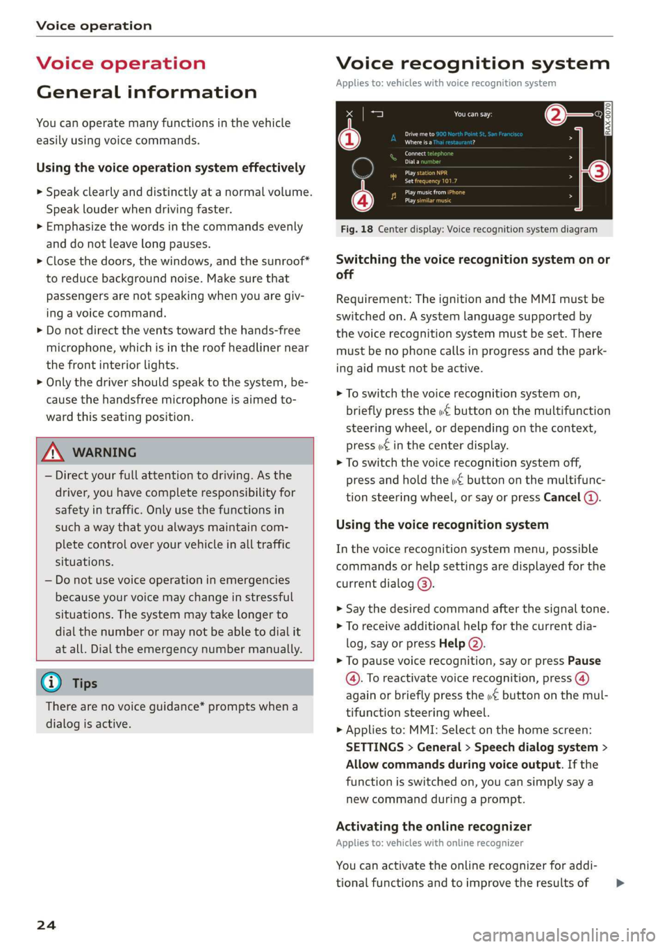
Fig. 18 Center display: Voice recognition system diagram
Switching the voice recognition system on or
off
Requirement: The ignition and the MMI must be
switched on. A system language supported by
the voice recognition system must be set. There
must be no phone calls in progress and the park-
ing aid must not be active.
> To switch the voice recognition system on,
briefly press the «€ button on the multifunction
steering wheel, or depending on the context,
press w£ in the center display.
> To switch the voice recognition system off,
press and hold the « button on the multifunc-
tion steering wheel, or say or press Cancel (a).
Using the voice recognition system
In the voice recognition system menu, possible
commands or help settings are displayed for the
current dialog @).
> Say the desired command after the signal tone.
> To receive additional help for the current dia-
log, say or press Help (2).
> To pause voice recognition, say or press Pause
@. To reactivate voice recognition, press (@)
again or briefly press the «€ button on the mul-
tifunction steering wheel.
> Applies to: MMI: Select on the home screen:
SETTINGS > General > Speech dialog system >
Allow commands during voice output. If the
function is switched on, you can simply say a
new command during a prompt.
Activating the online recognizer
Applies to: vehicles with online recognizer
You can activate the online recognizer for addi-
tional functions and to improve the results of >
Page 65 of 280
83A012721BA
Sitting correctly and safely
pred folacoy a)
RAZ-0239
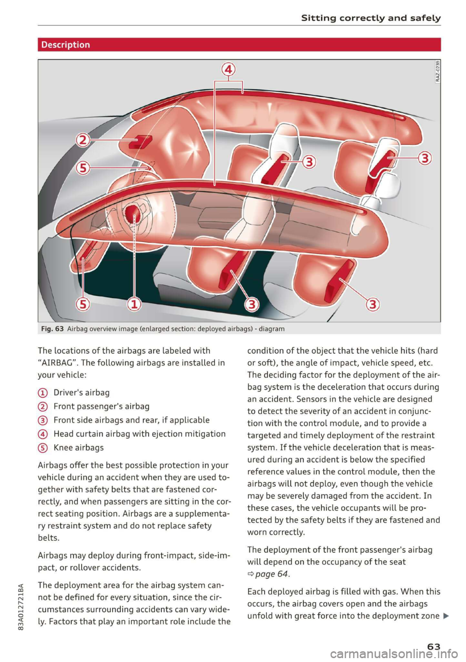
Fig. 63 Airbag overview image (enlarged section: deployed airbags) - diagram
The locations of the airbags are labeled with
“AIRBAG”. The following airbags are installed in
your vehicle:
Driver's airbag
Front passenger's airbag
Front side airbags and rear, if applicable
Head curtain airbag with ejection mitigation
Knee airbags COROTOTOTS)
Airbags offer the best possible protection in your
vehicle during an accident when they are used to-
gether with safety belts that are fastened cor-
rectly, and when passengers are sitting in the cor-
rect seating position. Airbags are a supplementa-
ry restraint system and do not replace safety
belts.
Airbags may deploy during front-impact, side-im-
pact, or rollover accidents.
The deployment area for the airbag system can-
not be defined for every situation, since the cir-
cumstances surrounding accidents can vary wide-
ly. Factors that play an important role include the
condition of the object that the vehicle hits (hard
or soft), the angle of impact, vehicle speed, etc.
The deciding factor for the deployment of the air-
bag system is the deceleration that occurs during
an accident. Sensors in the vehicle are designed
to detect the severity of an accident in conjunc-
tion with the control module, and to provide a
targeted and timely deployment of the restraint
system. If the vehicle deceleration that is meas-
ured during an accident is below the specified
reference values in the control module, then the
airbags will not deploy, even though the vehicle
may be severely damaged from the accident. In
these cases, the vehicle occupants will be pro-
tected by the safety belts if they are fastened and
worn correctly.
The deployment of the front passenger's airbag
will depend on the occupancy of the seat
=> page 64.
Each deployed airbag is filled with gas. When this
occurs, the airbag covers open and the airbags
unfold with great force into the deployment zone >
63
Page 108 of 280
Assist systems
@) Tips
— The coverage areas of the sensors > fig. 86
are diagrams and do not represent a true-
to-scale image of the sensor ranges. The ra-
dar sensors are designed to detect the left
and right adjacent lanes when the road
lanes
are the normal width.
— Make sure all the sensors are clean and free
of snow and ice, and that the visual fields
are not covered by stickers, deposits, or any
other obstructions, because this may impair
the function of the systems. Follow the in-
formation about cleaning > page 236.
— Do not use a license plate bracket different
from the one installed by the factory in the
front of the vehicle, because it may impair
the function of dependent systems.
— The sensors can shift from an accident,
manual force, impacts, or from damage to
the radiator grill, bumper, wheel housing,
or underbody. Do not continue using the as-
sistance systems if the sensors have shifted,
because this is unsafe. Have an authorized
Audi dealer or authorized Audi Service Fa-
cility check their function.
— The function of the sensors may be limited
when light and visibility conditions are poor,
for example when driving into a tunnel,
when there is glare, or when there are re-
flective objects.
— External ultrasonic sensors, such as those in
other vehicles, can interfere with the sen-
sors.
—The side area ©)* is detected and evaluated
when passing. There may have been
changes to the surrounding area after
switching the ignition off and on again, af-
ter opening the doors, or if the vehicle is left
stationary for a period of time. In this case,
the area will appear black until the area has
been detected and evaluated.
— For an explanation on conformity with the
FCC regulations in the United States and the
Industry Canada regulations, see
=> page 261.
106
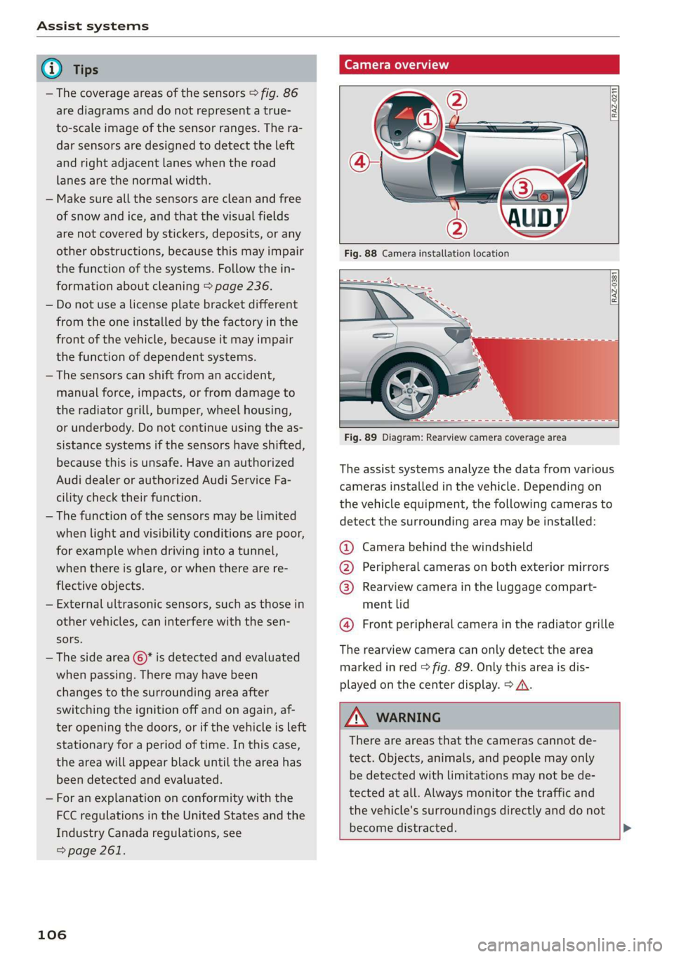
Camera overview
RAZ-0211 f
RAZ-0381 [
Fig. 89 Diagram: Rearview camera coverage area
The assist systems analyze the data from various
cameras installed in the vehicle. Depending on
the vehicle equipment, the following cameras to
detect the surrounding area may be installed:
@ Camera behind the windshield
@ Peripheral cameras on both exterior mirrors
@ Rearview camera in the luggage compart-
ment lid
@ Front peripheral camera in the radiator grille
The rearview camera can only detect the area
marked in red > fig. 89. Only this area is dis-
played on the center display. > A\.
ZA WARNING
There are areas that the cameras cannot de-
tect. Objects, animals, and people may only
be detected with limitations may not be de-
tected at all. Always monitor the traffic and
the vehicle's surroundings directly and do not
become distracted. >
Page 109 of 280
Assist systems
83A012721BA
® Note sun shining into the lens, by dirt on the
lens, or if there is a malfunction.
— Obstacles may disappear from the measure- — The camera view on the display portrays an
ment range when approaching them, even if enlarged and distorted image. Under cer-
they were already detected. Under certain
circumstances, the detection and display of
certain surfaces and objects may be limited:
tain circumstances, objects may appear dif-
ferent and unclear on the display.
— Items and objects above the coverage
area, for example cars parked bumper-to-
bumper, half-open garage doors, or hang-
ing objects that do not touch the ground
— Low obstacles
—Thin or narrow objects, such as barrier
chains, foliage, poles or fences
— Projecting objects, such as trailer draw
bars
— Objects with certain surfaces and struc-
tures, such as fabric
@ Tips
— The coverage areas of the cameras > fig. 88
and > fig. 89 are diagrams and do not repre-
sent a true-to-scale image of the camera
coverage areas.
— Make sure all the cameras are clean and free
of snow and ice, and that the lenses are not
covered by stickers, deposits, or any other
obstructions, because this may impair the
function of the systems. Follow the infor-
mation about cleaning > page 236.
— Do not use a license plate bracket different
from the one installed by the factory in the
front of the vehicle, because it may impair
the function of dependent systems.
— The camera can shift from an accident, man-
ual force, impacts, or from damage to the
radiator grill, bumper, wheel housing or un-
derbody. Have an authorized Audi dealer or
authorized Audi Service Facility check their
function.
— The function of the cameras may be limited
when light and visibility conditions are poor,
for example when driving into a tunnel,
when there is glare, or when there are re-
flective objects.
— Use the image on the display to assist you
only if it shows a good, clear picture. For ex-
ample, the image may be affected by the
107
Page 110 of 280
Driving information
Driving information
Speed warning system
Applies to: vehicles with speed warning system
The speed warning system helps the driver to
stay below a specified maximum speed. A warn-
ing threshold can be set for this purpose.
Once the speed slightly exceeds the stored
threshold, the speed warning system will alert
the driver with an indicator in the instrument
cluster and a warning tone. Once the speed drops
below the stored maximum speed, the indicator
will turn off.
Setting a threshold is recommended if you would
like to be reminded when you reach a certain
maximum speed. Situations where you may want
to do so include driving in a country with a gener-
al speed limit or if there is a specified maximum
speed for winter tires.
G) Tips
Regardless of the speed warning system, you
should always monitor your speed using the
speedometer and make sure you are following
the legal speed limit.
Setting the warning threshold
Applies to: vehicles with speed warning system
» Applies to: MMI: Select on the home screen:
VEHICLE > Driver assistance > Speed warning.
CEE Tel
Applies to: vehicles with speed warning system
cy Manually set XX speed limit warning
threshold exceeded
The stored speed was exceeded.
108
Traffic light information
Applies to: vehicles with traffic light information
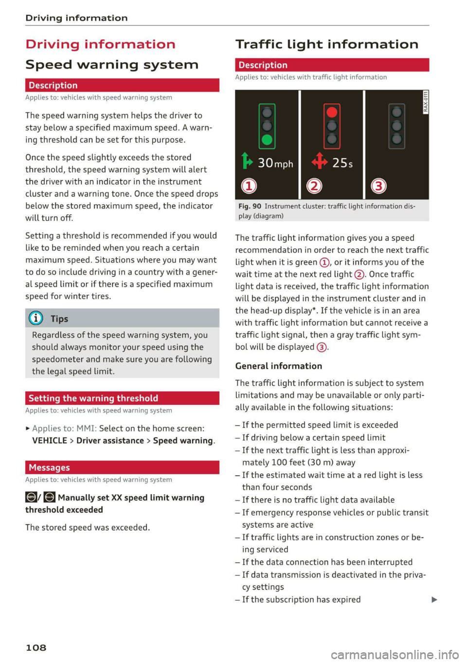
Fig. 90 Instrument cluster: traffic light information dis-
play (diagram)
The traffic light information gives you a speed
recommendation in order to reach the next traffic
light
when it is green ©, or it informs you of the
wait time at the next red light 2). Once traffic
light data is received, the traffic light information
will be displayed in the instrument cluster and in
the head-up display*. If the vehicle is in an area
with traffic light information but cannot receive a
traffic light signal, then a gray traffic light sym-
bol will be displayed @).
General information
The traffic light information is subject to system
limitations and may be unavailable or only parti-
ally available in the following situations:
— Ifthe permitted speed limit is exceeded
— If driving below a certain speed limit
—If the next traffic light is less than approxi-
mately 100 feet (30 m) away
—If the estimated wait time at a red light is less
than four seconds
—If there is no traffic light data available
— If emergency response vehicles or public transit
systems are active
— If traffic lights are in construction zones or be-
ing serviced
— If the data connection has been interrupted
— If data transmission is deactivated in the priva-
cy settings
— If the subscription has expired
Page 131 of 280
83A012721BA
Parking and maneuvering
— Sensors and cameras have spots in which
the surrounding area cannot be detected.
Objects, animals, and people may only be
detected with limitations may not be detect-
ed at all. Always monitor the traffic and the
vehicle's surroundings directly and do not
become distracted.
@) Note
— Keep enough distance from the curb to
avoid damage to the rims.
— Applies to: vehicles with park assist: If you
park in short parking spaces using park as-
sist, a continuous tone sounds from the
parking system when the distance to an ob-
ject is less than approximately 0.7 ft
(0.20 m). Do not continue driving farther.
G) Tips
— The segments in the side area* are detected
and analyzed when passing. There may have
been changes to the surrounding area after
switching the ignition off and on again, af-
ter opening the doors, or if the vehicle is left
stationary for a long period of time. In this
scenario, the side area* will appear black
until the area has been detected and evalu-
ated.
— If the distance to an obstacle remains con-
stant, the volume of the distance warning
gradually lowers after a few seconds until it
is muted (this does not apply to the continu-
ous tone). If the obstacle comes closer than
it was before the sound was muted, the
tone will sound again. If the obstacle be-
comes farther away than it was before the
sound was muted, no tone will sound. Pay
attention to the vehicle's surroundings
when you start to drive.
— There is no distance warning for the rear
and the sides* when trailer towing mode is
detected. The front sensors remain activat-
ed. The visual display switches to trailer
mode. There is no guarantee the functions
will switch off when using a retrofitted trail-
er hitch.
Rearview camera and
peripheral cameras
Introduction
Applies to: vehicles with rearview camera/peripheral cameras
B8V-0629
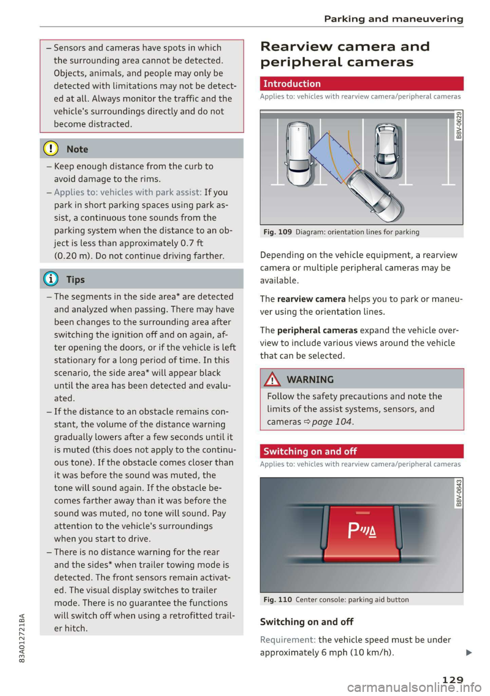
Fig. 109 Diagram: orientation lines for parking
Depending on the vehicle equipment, a rearview
camera or multiple peripheral cameras may be
available.
The rearview camera helps you to park or maneu-
ver using the orientation lines.
The peripheral cameras expand the vehicle over-
view to include various views around the vehicle
that can be selected.
Z\ WARNING
Follow the safety precautions and note the
limits of the assist systems, sensors, and
cameras > page 104.
Switching on and off
Applies to: vehicles with rearview camera/peripheral cameras
B8V-0643
Fig. 110 Center console: parking aid button
Switching on and off
Requirement: the vehicle speed must be under
approximately 6 mph (10 km/h).
129
Page 136 of 280
Parking and maneuvering
— Once an automatic brake activation occurs,
the system cannot brake automatically
again for several seconds.
—If there is an acoustic warning signal from
the rear cross-traffic assist, then the park-
ing system may not warn you of detected
obstacles under certain circumstances.
— The system is not available when the vehicle
detects that you are towing a trailer. There
is no guarantee the functions will switch off
when using a retrofitted trailer hitch. Do not
use
these functions when towing a trailer.
— For an explanation on conformity with the
FCC regulations in the United States and the
Industry Canada regulations, see
=> page 261.
Assisted parking
(er eee)
Applies to: vehicles with park assist
If your vehicle is equipped with park assist, this
system helps you find suitable parking spaces.
Parking spaces are measured using ultrasonic
sensors on the sides of the vehicle.
If a parking space is found, the system helps you
to park while the driver monitors the vehicle's
surroundings with the parking aids, cameras”,
and direct eye contact. The vehicle moves the
steering wheel autonomously.
Follow the safety precautions and note the
limits of the assist systems, sensors, and
cameras > page 104.
134
Parking options
Applies to: vehicles with park assist
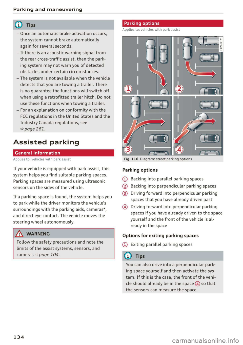
Fig. 116 Diagram: street parking options
Parking options
Backing into parallel parking spaces
Backing into perpendicular parking spaces
Driving forward into perpendicular parking
spaces that you have already driven past
®
©80
Driving forward into perpendicular parking
spaces if you have already driven to the space
yourself and the front of the vehicle is al-
ready in the space
Options for exiting parking spaces
@ Exiting parallel parking spaces
You can also drive into a perpendicular park-
ing space yourself and then activate the sys-
tem. If this is the case, the front of the vehi-
cle should already be in the space (4) so that
the sensors can measure the space.