center console AUDI Q5 2013 Owners Manual
[x] Cancel search | Manufacturer: AUDI, Model Year: 2013, Model line: Q5, Model: AUDI Q5 2013Pages: 316, PDF Size: 78.89 MB
Page 53 of 316
Canada models : The function cannot be
turned off.
It is activated a utomatica lly each
time the ignition is switched on.
Travel mod e (Canada models)*
The headlight beam is asymmetrical. This pro
vides stronge r illum ination on the s ide of the
road on which you are driving . If you are driv
ing in a co untry that drives on the opposite
side of the road from your own country, this
will cause glare for oncoming drivers. To pre
vent glare:
- Trave l mode must be selected in vehicles
with Xenon headlights*.
- In vehicles with halogen headlights, certain
areas of the head light lenses must be cov
ered with waterproof adhesive covers that
prevent light from passing through. For
more information, please see your author
ized Audi dealer or author ized repair facility .
@ Tips
When travel mode* is activated, a d isp lay
in the drive r information system ind icates
this each time you switch the ignit io n on .
Instrument lighting
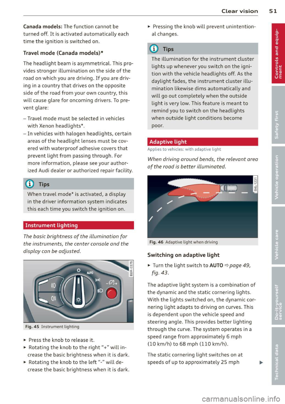
The basic brightness of the illumination for
the instruments, the center console and the
display can be adjusted .
Fig. 45 Inst rume nt lighting
.. Pres s the knob to release it.
.. Rota ting the knob to the rig ht" +" will in
c rease the basic brightness when it is dark .
.. Rotating the knob to the left"-" will de
crease the bas ic br ightness when it is dark. Clear vi
sion 51
.. Pressing the knob will p revent un intention
al changes.
(D Tips
T he ill umination for the instrument cluster
lights up w henever you switch on the igni
tion with the vehicle headlights off. As the
day light fades, the instrument cluster i llu
mination likewise dims automatica lly and
will go out completely when the outside li ght is very low. This feature is meant to
r emind you to switch on the head lights
whe n outside lig ht conditions become
p oor .
Adaptive light
Applies to vehicles: wi th adaptive light
Wh en driving around bends, the relevant area
of the road is be tter illuminated.
Fi g. 4 6 Adapt ive light w hen driv ing
Switching on adapt ive light
.. Turn t he light switch to AUTO ¢ page 49,
fig. 43 .
The adaptive lig ht system is a combin ation o f
the dynam ic and the static corneri ng lights.
Wi th the lights switched on, the dynamic cor
ner ing light adapts to driving on curves. This
is dependent upon t he vehicle speed and
steering ang le. This provides better lighting
through the curve. The system operates in a
speed range from approximate ly 6 mph
(10 km/h) to 68 mph (110 km/h) .
The static cornering light switches on at
speeds of up to approximately 25 mph
Page 76 of 316
7 4 Seats and storage
Climatized cupholders
Appl ies to vehicles: wit h clim atized beverage holders
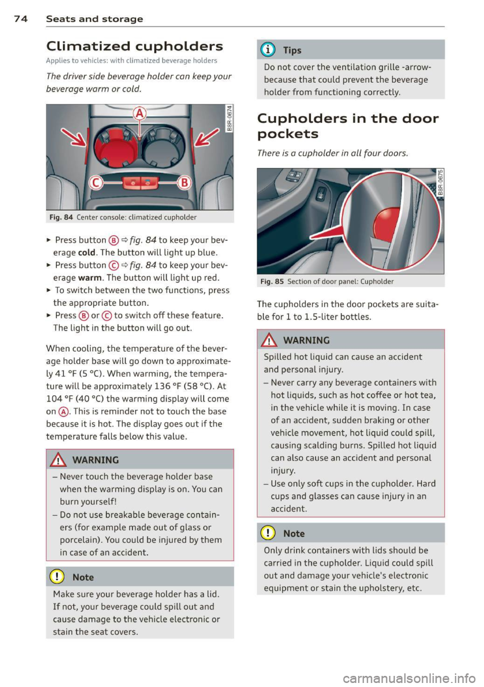
The driver side beverage holder can keep your
beverage warm or cold.
Fi g. 8 4 Center console: cl imat ized cupholder
.,. Press button ®~ fig. 84 to keep you r bev
erage
cold . The button w ill light up b lue .
.,. Press button ©~
fig. 84 to keep your bev
erage
warm . The button will light up red .
.,. To sw itch between the two func tions, press
the appropriate button.
.,. Press ® or© to switch off these feature .
The light in the button will go o ut.
When cooling, the temperature of the bever
age holde r base will go down to approximate
l y 41
°F (5 °C). When warming, the tempera
ture w ill be approximately 136
°F (58 °(). At
104
°F (40 °() the warm ing display will come
on @. This is reminder not to touch the base
because it is hot . The disp lay goes out if the
temperature falls be low this value.
_& WARNING
- Never to uch the beverage ho lde r base
when the warm ing display is on. Yo u can
burn yourse lf!
- Do not use breakable beverage con tain
ers (for example made out of glass o r
porcelain). Yo u could be injured by them
in case of an acc ident.
(D Note
Ma ke sure you r beverage holder has a lid.
I f not, yo ur beverage could spill out and
cause damage to t he ve hicle elec tronic or
stain th e seat cove rs .
-
(D Tips
Do not cover the ventilation grille -arrow
because that could prevent the beverage
ho lder from functioning correctly.
Cupholders in the door
pockets
There is a cupholder in all four doors.
F ig . 85 Sect ion of door panel: (upholder
The cupholders in the doo r pockets are suita
ble for
l to 1.5-liter bott les.
.&_ WARNING
-==
Spilled hot liquid can cause an accident
and personal injury.
-
- Never carry any beverage containers with
hot liq uids, such as hot coffee or hot tea,
in the vehicle while it is moving. In case
of an accident, sudden braking or othe r
veh icle movement, hot liquid could spill,
causing scalding burns. Spilled hot liquid
can also cause an a ccident and pe rsonal
in jur y.
- Use on ly soft cups in the cupholder . Hard
cups and glasses can cause injury in a n
accident.
0 Note
Only drink conta iners with lids should be
ca rried in the cuphold er. L iquid could spill
out and damage you r vehicle's electron ic
equipment or stain the upho lstery, etc.
Page 77 of 316
Ashtray
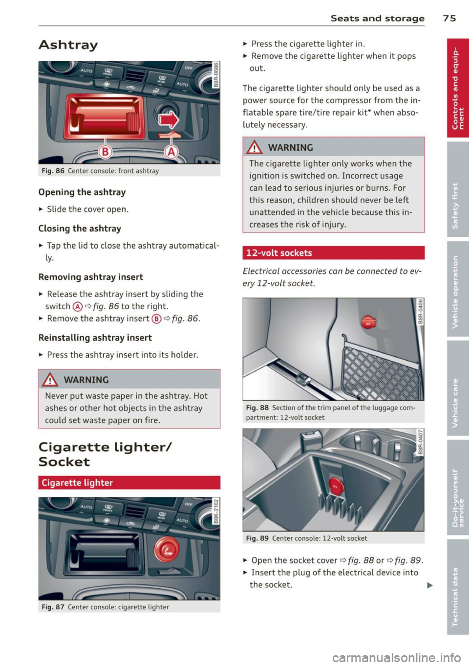
Fig. 86 Center console: front ashtray
Opening the ashtray
.,. Slide the cover open .
Closing the ashtray
.,. Tap the lid to close the ashtray automatical
ly.
Removing ashtray insert
.,. Re lease the ashtray insert by sliding the
switch @c:>
fig. 86 to the right .
.,. Remove the ashtray insert@
c:> fig. 86 .
Reinstalling ashtray insert
.,. Press the ashtray insert into its holder .
_& WARNING
Never put waste paper in the ashtray . Hot
ashes or othe r hot objects in the ashtray
cou ld set waste paper on fire.
Cigarette Lighter/
Socket
Cigarette lighter
Fig. 87 Ce nter console: c igarette lighter
Seats and storage 75
.,. Press the cigarette lighter in .
.,. Remove the cigarette lighter when it pops
out .
The cigarette lighter should only be used as a
power source for the compressor from the in
flatable spare tire/tire repair kit* when abso
lutely necessary.
_& WARNING
The cigarette lighter only works when the ignition is switched on. Incorrect usage
can lead to ser ious injuries or burns. For
this reason, ch ildren should never be left
unattended in the vehicle because this in
creases the risk of injury.
12-volt sockets
Electrical accessories can be connected to ev
ery 12-volt socket.
Fig. 88 Section of the t rim pane l of the luggage com
partme nt: 12-volt socket
Fig. 89 Center console: 12-volt socket
I er a, m
.,. Open the socket cover c:> fig. 88 or c:> fig . 89 .
.,. Insert the plug of the electrical device into
the socket. .,.
Page 78 of 316
76 Seats and storage
The 12-volt sockets can be used for electrical
accessories. The power input must not exceed
120 watts.
There is an additional 12-volt socket in the
center console. Before you purchase any accessories, always
read and follow the information in
~ page 29 7, Additional accessories and parts
replacement.
A WARNING
The power outlets and therefore the elec
trical accessories connected to them oper ate only with the ignition on. Improper use
of the outlets or of electrical accessories
can lead to serious injuries or cause a fire.
For this reason, children should never be
left unattended in the vehicle -they could
be injured!
(D Note
To avoid damaging the socket, only use
plugs that fit properly .
{D) Tips
When the engine is off and accessories are
still plugged in and are on, the vehicle bat
tery can still be drained .
Storage
General overview
There are numerous places to store items in
your vehicle.
Glove compartment 9 page 76
Cooling box in glove compart-
9 page 77
ment
Storage compartment in the
roof
Multi-use attachment
Coat hooks
Storage in the door panels
Storage net in footwell
9page 77
9page 77
9page 78
-
Storage net in the front seat
backs
Storage net in luggage com
partment
A WARNING
--
- Always remove objects from the instru
ment panel. Any items not put away
could slide around inside the vehicle
while driving or when accelerating or
when applying the brakes or when driv ing around a corner.
- When you are driving make sure that
anything you may have placed in the cen
ter console or other storage locations
cannot fall out into the footwells. In case
of sudden braking you would not be able
to brake or accelerate.
- Any pieces of clothing that you have
hung up must not interfere with the driv
er's view. The coat hooks are designed
only for lightweight clothing. Never hang
any clothing with hard, pointed or heavy
objects in the pockets on the coat hooks .
During sudden braking or in an accident -
especially if the airbag is deployed -
these objects could injure any passen
gers inside the vehicle.
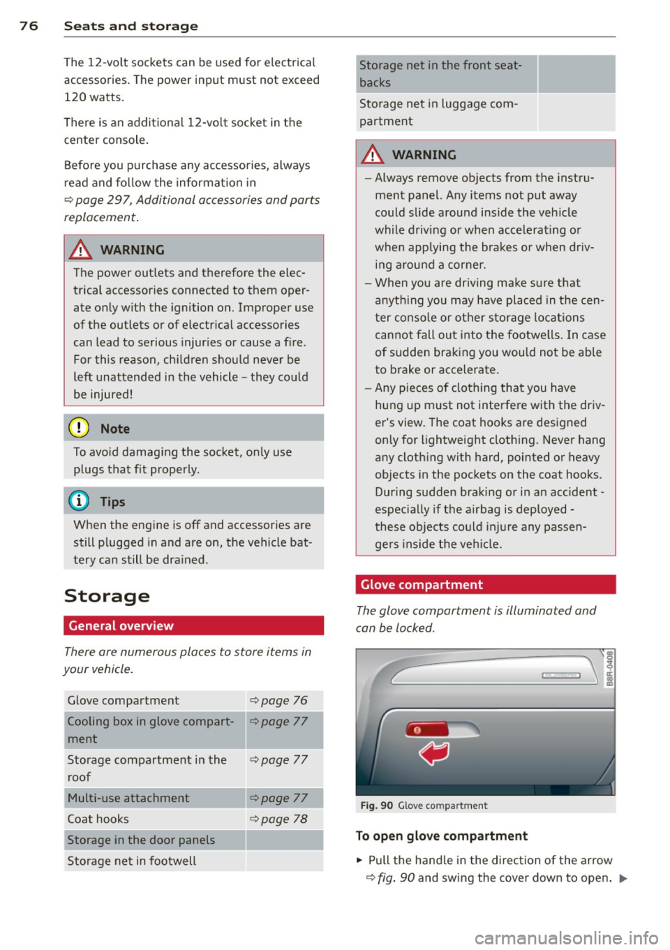
Glove compartment
The glove compartment is illuminated and
can be locked .
Fig. 90 Glov e co mpartm ent
To open glove compartment
.,. Pull the handle in the direction of the arrow
9 fig. 90 and swing the cover down to open . ..,.
Page 88 of 316
86 On the road
(D Note
If the engine has been under heavy load
for an extended period, heat builds up in
the engine compartment after the engine
is switched off -there is a risk of damaging
the engine. Allow the engine to run at idle
for about two minutes before switching it
off.
Convenience key
Starting the engine
Appl ies to vehicles: with Convenience key
The I STAR T ENGINE S TOP! button switches
the ignition on and starts the engine .
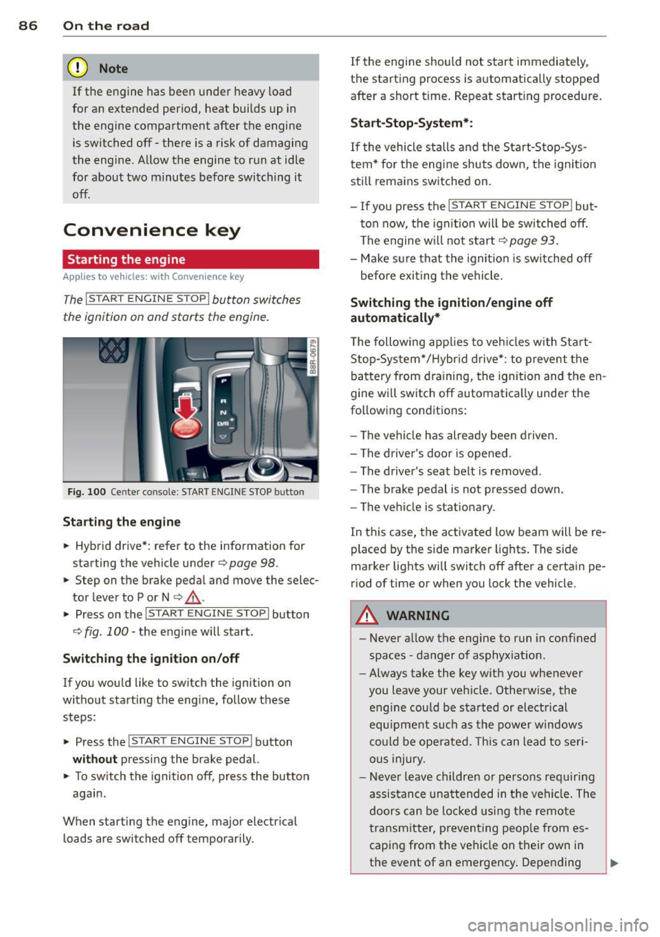
Fig. 100 Center console: START ENGINE STOP butto n
Starting the engine
.. Hybrid drive* : refer to the information for
starting the vehicle under
¢ page 98 .
.. Step on the brake peda l and move the selec
tor lever to P or N
¢ ,& .
.. Press on the r:I s==T::-:: A--=R== T=-c E=-c N:-;--:::: G-.,,.I ::-:N-;::: E-,S== T;:-; O:;--;P:cil button
c;, fig . 100 -the engine will start .
Switching the ignition on/off
If you would like to switch the ignition on
without starting the eng ine, follow these
steps :
.. Press the
!START ENGINE STOP! button
without pressing the brake pedal.
.. To sw itch the ignition off, press the button
again .
When starting the engine, major electr ical
loads are switched off temporarily . If
the engine should not start immediately,
the starting process is automatically stopped
after a short t ime. Repeat start ing procedure.
Start -Stop-System*:
If the vehicle stalls and the Start-Stop-Sys
tem* for the eng ine shuts down, the ignition
still remains switched on.
- If you press the
I START ENGINE STOP I but
ton now, the ignitio n will be switched off.
The engine w ill not start
¢page 93.
-Make sure that the igni tion is sw itched off
befo re exiting the vehicle.
Switching the ignition /engine off
automatically*
T he following app lies to veh icles with Start
Stop-System*/Hybrid drive*: to prevent the
battery from draining, the ignition and the en
gine wi ll switch off automatically unde r the
following conditions:
- The vehicle has already been driven.
- The driver's door is opened .
- The driver 's seat belt is removed .
- The brake pedal is not pressed down .
- The vehicle is stat ionary.
In this case, the activated low beam will be re
placed by the side marker lights. The side
marker lights wi ll switch off after a certain pe
riod of time or when you lock the vehicle.
A WARNING
--Never allow the engine to run in conf ined
spaces -danger of asphyx iat ion.
- Always take the key with you whenever
you leave your veh icle. Otherw ise, the
engine could be sta rted or electrical
equ ipment such as the power windows
could be operated. This can lead to seri
ous injury.
- Never leave children or persons requiring
assistance unattended in the vehi cle. The
doors can be locked us ing the remote
transmitter, preventing people from es
caping from the veh icle on their own in
the event of an emergency . Depending
Page 95 of 316
- After engaging the reverse gear.
er.
Engine automatically restarts
The stop phase is interrupted in the following
situations, for example . The engine restarts
without any act ion by the driver .
- The interior temperature varies from the
temperature selected in the A/C system.
- The windshield is beeing defrosted
Q page 81.
-The brake pedal is pressed several times in a
row.
- The battery charge level becomes too low.
- High power consumption .
@ Tips
If you shift into the 0/5 or N positions af
ter shifting into reverse, the vehicle must
be driven faster than 6 mph (10 km/h) in
order for the engine to switch off again.
Switching the Start-Stop-System on/off
manually
Applies to vehicles: with Sta rt-Stop-System
If you do not wish to use the system, you can
switch it off manually .
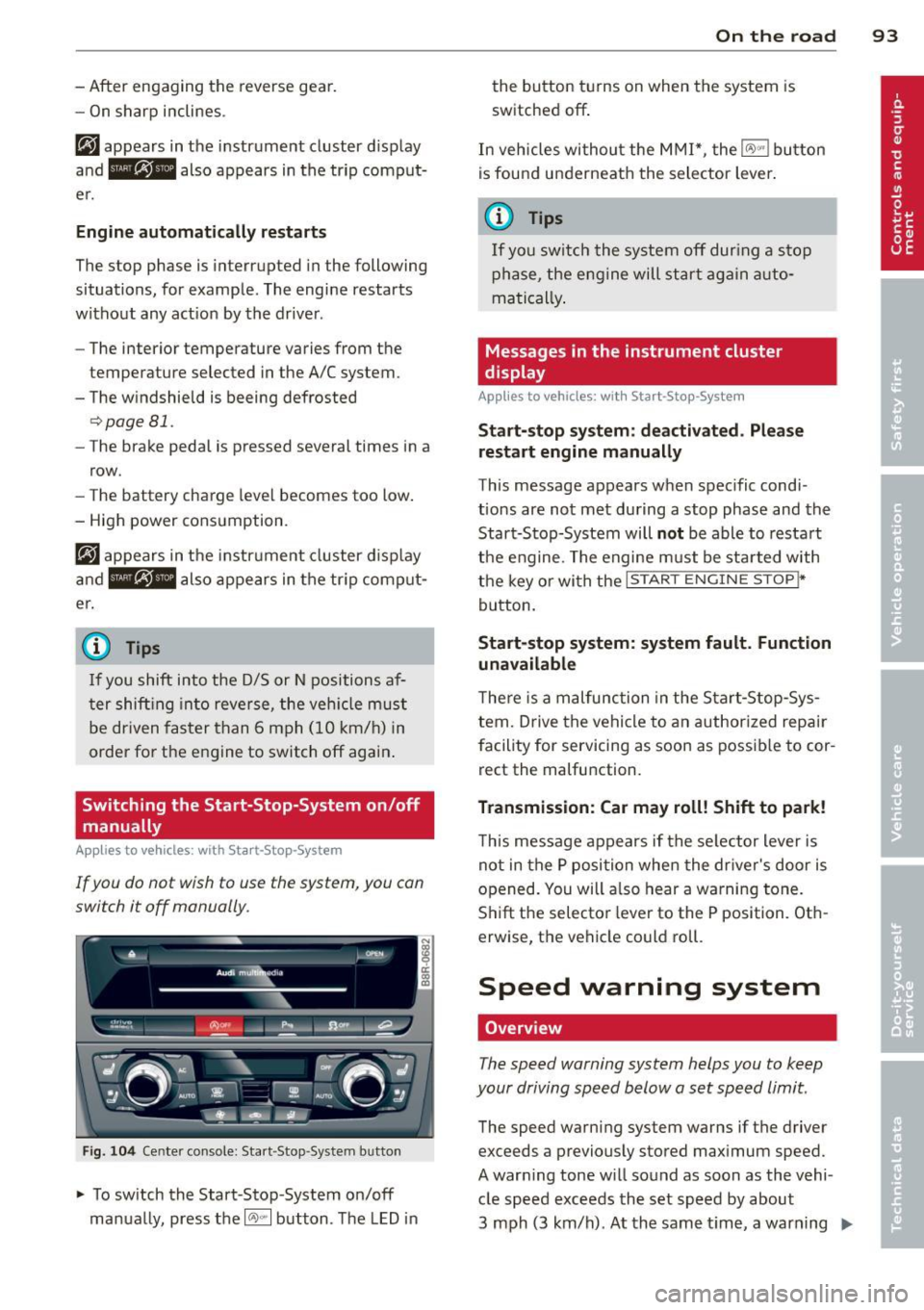
Fig. 104 Center console: Start -Stop -System button
.,. To switch the Start-Stop -System on/off
manually, press the
1 (1;)~ 1 button . The LED in
On the road 93
the button turns on when the system is
switched off .
In vehicles without the MMI*, the
IO\> .. j button
is found underneath the selector lever .
(j} Tips
If you switch the system off during a stop
phase, the engine will start again auto
matically.
Messages in the instrument cluster
display
App lies to vehicles: wit h Start-Stop-Syste m
Start-stop system: deactivated . Please
restart engine manually
This message appears when specific condi
tions are not met during a stop phase and the
Start-Stop-System will
not be able to restart
the engine. The engine must be started with
the key or with the
I STAR T ENGINE STOP t*
button.
Start-stop system: system fault. Function
unavailable
There is a malfunction in the Start-Stop-Sys
tem. Drive the vehicle to an authorized repair
facility for servicing as soon as possible to cor
rect the malfunction.
Transmission: Car may roll! Shift to park!
This message appears if the selector lever is
not in the P position when the driver's door is
opened. You will a lso hear a warning tone.
Shift the selector lever to the P position . Oth
erw ise, the vehicle could roll.
Speed warning system
Overview
The speed warning system helps you to keep
your driving speed below a set speed limit.
The speed warning system warns if the driver
exceeds a previously stored maximum speed.
A warning tone will sound as soon as the vehi cle speed exceeds the set speed by about
3 mph (3 km/h) . At the same time, a warning
IJJ,,
Page 102 of 316
100 Hybrid
Hybrid battery: Low battery charge.
B attery will be charged while driving.
This message appears if the high voltage bat
tery charge level has fa llen below a certain
range. If this message turns off after a little
while, the high voltage battery charged
enough while dr iv in g.
If the message does not turn off, have an au
thorized repair fac ility correct the malfunction
as soon as possible.
EV mode is currently unavailable .
This message appears if the conditions
¢
page 100 for enhanced e lectric driving are
not met. Try again at a later time.
Hybrid functions and operating modes
App lies to vehicles: with hybrid dr ive
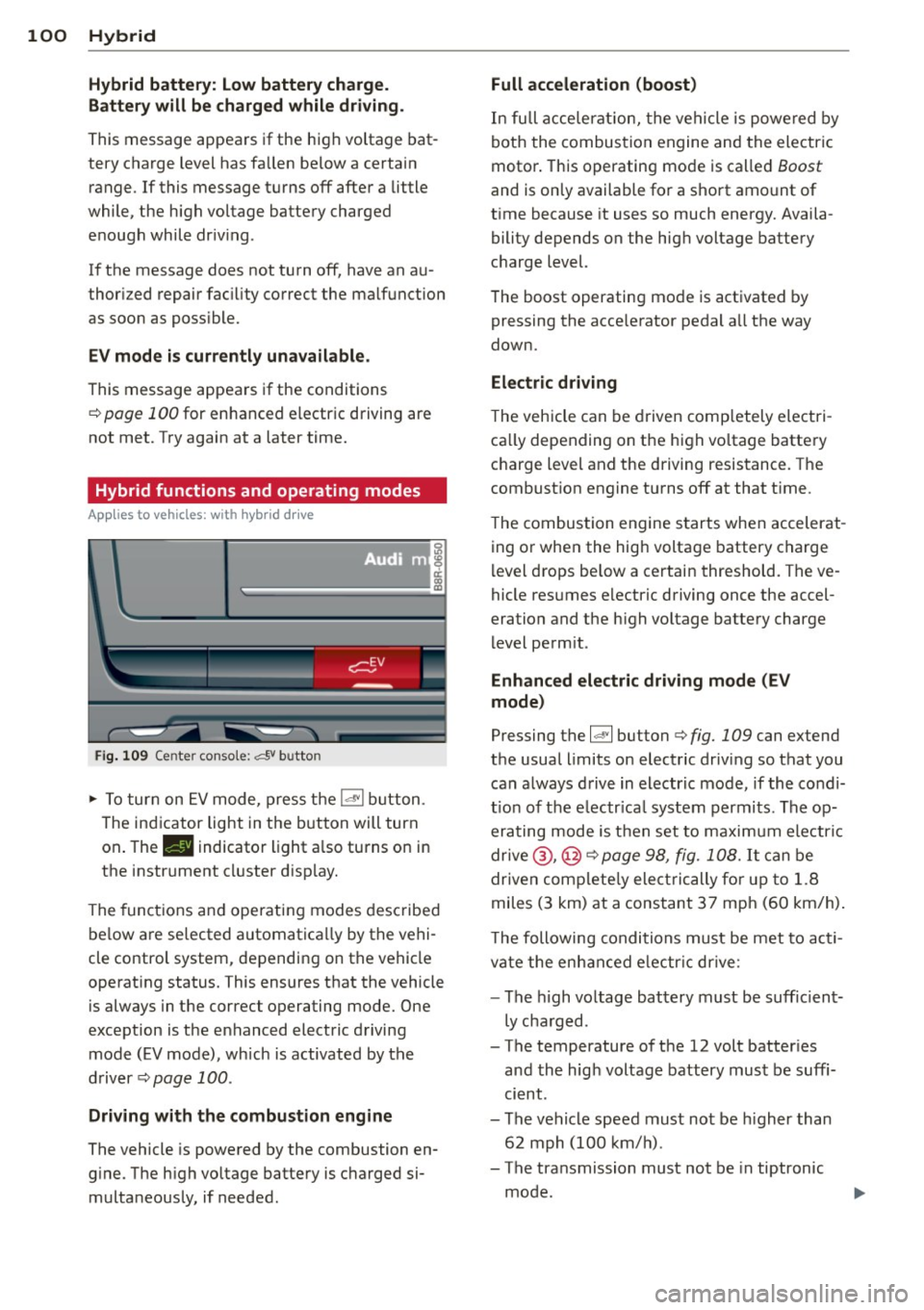
Fig. 109 Center console: c:f,V button
.,. To turn on EV mode, press the ld"I button .
The indicator light in the button will turn
on . The. indicator light a lso turns on in
the instrument cluster display.
The functions and operating modes described
be low are se lected automatica lly by the vehi
cle control system, depending on the vehicle
operat ing status. This ensures that the vehicle
is always in the correct operating mode. One
exception is the enhanced electric driving
mode (EV mode), which is activated by the
driver
¢pag e 100.
Driving with the combustion engine
The vehicle is powered by the combustion en
gine. The h igh voltage battery is charged si
multaneously, if needed.
Full acceleration (boost)
In full acceleration, the vehicle is powered by
both the combustion engine and the electric
motor . This operating mode is called
Boost
and is on ly available for a short amount of
time because it uses so much energy. Availa
bility depends on the high voltage battery
charge level.
The boost operating mode is activated by
pressing the accelerator pedal all the way
down.
Electric driving
The vehicle can be driven completely electri
ca lly depending on the high vo ltage battery
charge level and the driving resistance. The
combust ion eng ine turns off at that t ime.
The combustion engine starts when accelerat
ing or when the high voltage battery charge
level drops be low a certain threshold. The ve
hicle resumes e lectric driving once the accel
eration and the high voltage battery charge
level permit.
Enhanced electric driving mode (EV
mode)
Pressing the 1~ 1 button ¢ fig. 109 can extend
the usual limits on electric driving so that you
can always drive in electric mode, if the condi
t ion of the e lectr ica l system permits . The op
erating mode is then set to maximum electric
drive @,@ ¢
page 98, fig. 108. It can be
driven complete ly elec trically for up to 1.8
miles (3 km) at a constant 37 mph (60 km/h) .
T he following conditions must be met to act i
vate the enhanced e lectr ic drive:
- The high voltage battery must be suffic ient
ly charged.
- The temperature of the 12 volt batter ies
and the hig h voltage battery must be suffi
cient.
- The vehicle speed must not be higher than
62 mph (100 km/h).
- The transmission must not be in tiptronic
mode.
Page 133 of 316
Switching on and off
Applies to vehicles: with Audi parking system p lus with
rea rview camera
The reorview camera switches on automati
cally together with the acoustic and visual
pork assist when you put the vehicle in re verse .
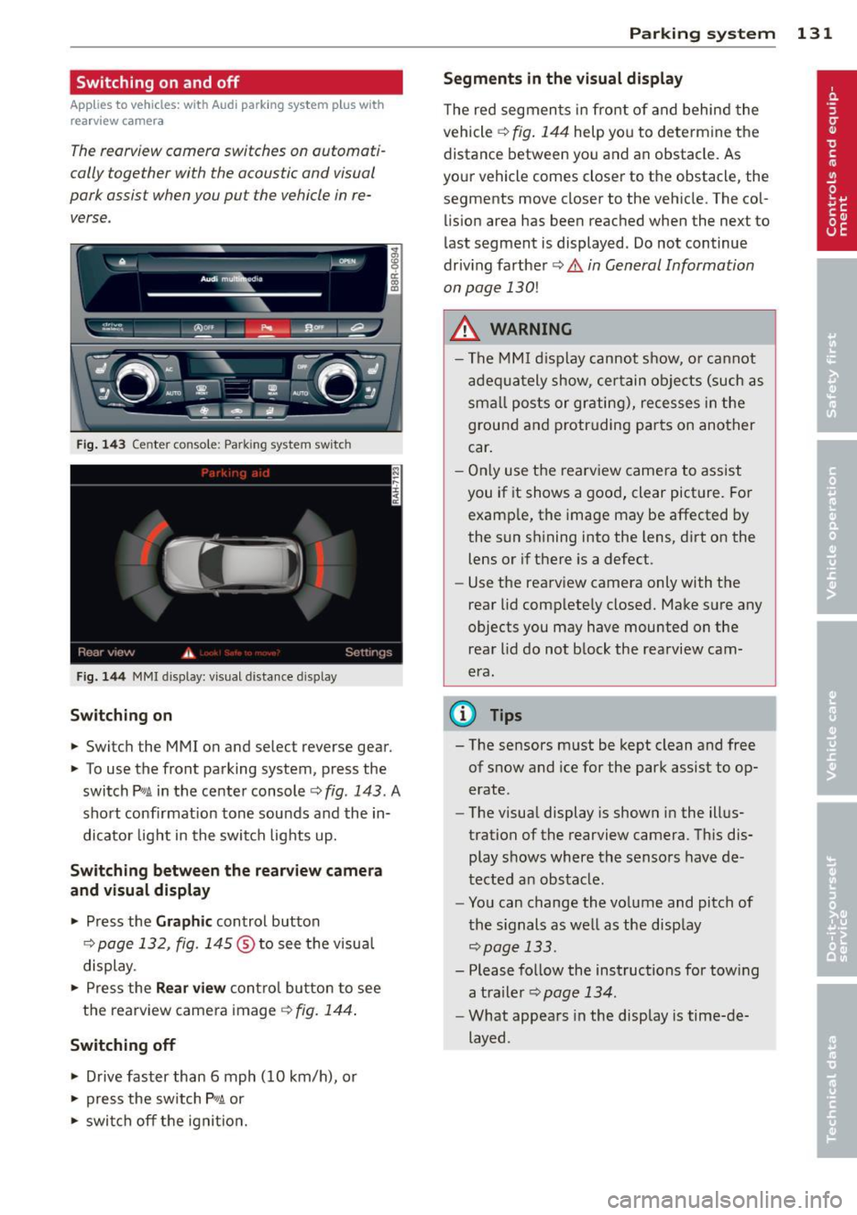
Fig. 14 3 Center co nsole ; Pa rk ing syste m switc h
Fig. 144 MMI disp lay: visu al dista nce display
Switching on
.,. Switch the MMI on and select reverse gear.
.,. To use the front parking system, press the
switch
P w.A in the center console c> fig . 143. A
sho rt confirmat ion tone sounds and the in
dicato r light in the switch lights up.
Switching between the rear view came ra
and visual display
.,. Press the Graphic control button
¢ page 132, fig . 145 ® to see the visua l
display.
.,. Press the
Rear view con trol bu tton to see
the rearview came ra image
¢ fig. 144 .
Switching off
.,. Drive faster than 6 mph (10 km/h), or
.,. press the sw itch
p ,q .A or
.,. swi tch off the ignit io n.
Par king system 131
Segm ents in the vi sual display
T he red segmen ts i n fro nt of and behind the
vehicle
c> fig . 144 help you to determ ine the
distance between yo u and an obstacle. As
you r vehicle comes close r to the obstacle, the
segments move closer to the vehicle. The col lision area has been reached when the next to
l ast segment is displayed . Do not continue
driv ing farther
c> .&. in General Information
on page
130!
A WARNING
- T he MMI display cannot s how, o r ca nnot
a dequa tely show, certain o bje cts (such as
smal l posts or gr ating), recesses in the
ground and p rotruding parts on another
car .
- On ly use the rearv iew came ra to assist
you if it shows a good, clear pict ure. For
examp le, the image may be affected by
the sun sh ining into the lens, d irt on the
lens or if there is a defect.
- Use the rearv iew camera only with the
rear lid comp lete ly closed. Make sure any
o bjects you may have mounted on the
rea r lid do not b lock the rearview cam
era.
(D Tips
- The sensors m ust be kept clean and free
of snow and ice for the park assist to op
erate .
- The visua l display is shown in the illus
tration of the rearview camera. Th is dis
play shows where the sensors have de
tected an obstacle .
- You can change the vo lume and pitch of
t he s ignals as we ll as the disp lay
<=>page 133.
- Please fo llow the instructions for tow ing
a tra iler
c> page 134.
-What appears in the display is time-de
layed .
Page 174 of 316
172 Airbag system
dealer is familiar with these requirements
and we recommend that you have your
dealer perform this service for you.
Other things that can affect Advanced
Airbag performance
Changing the vehicle's suspension system can
change the way that the Advanced Airbag Sys
tem performs in a crash. For example, using
tire-rim combinations not approved by Audi, lowering the vehicle, changing the stiffness of
the suspension, including the springs, suspen
sion struts, shock absorbers etc. can change
the forces that are measured by the airbag
sensors and sent to the electronic control
unit. Some suspension changes can, for exam ple, increase the force levels measured by the
sensors and make the airbag system deploy in
crashes in which it would not deploy if the
changes had not been made . Other kinds of
changes may reduce the force levels meas
ured by the sensors and prevent the airbag
from deploying when it should.
The sensors in the safety belt buckle for the
driver and front passenger seat tell the elec
tronic control module if the safety belt is
latched or not.
If the safety belt is being used,
the front airbag will deploy at a slightly high
er rate of vehicle deceleration than if the safe
ty belt is not being used. Therefore, in a par
ticular collision, it is possible that an airbag
will not deploy at a seating position where the
safety belt is being used but will inflate at the
position where the safety belt is not being
used. It is important that nothing interfere
with the safety belt buckles so that the sen
sors can send the correct information about
safety belt use to the electronic control unit.
A WARNING
Changing the vehicle's suspension includ
ing use of unapproved tire-rim combina
tions can change Advanced Airbag per
formance and increase the risk of serious
personal injury in a crash.
- Never install suspension components
that do not have the same performance characteristics as the components origi
nally installed on your vehicle.
- Never use tire-rim combinations that
have not been approved by Audi.
A WARNING
= -
Items stored between the safety belt
buckle and the center console can cause
the sensors in the buckle to send the
wrong information to the electronic con
trol module and prevent the Advanced Air
bag System from working properly.
- Always make sure that nothing can inter
fere with the safety belt buckles and that
they are not obstructed.
Side airbags
Description of side airbags
The airbag system can provide supplemental
protection to properly restrained occupants.
Fig. 170 S ide a irbag location in the driver's seat
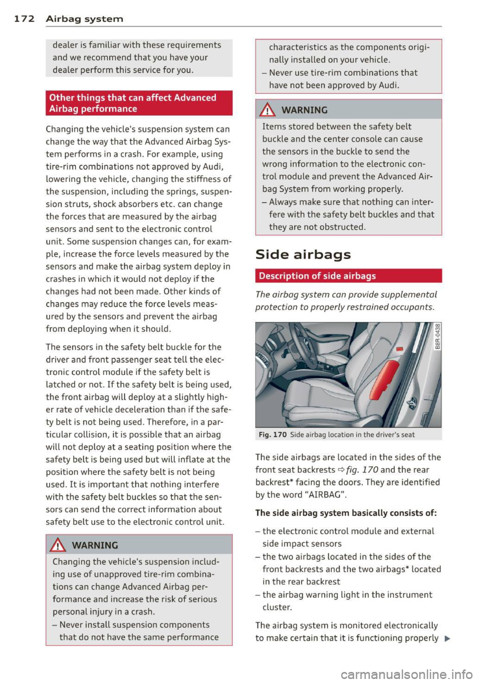
The side airbags are located in the sides of the
front seat backrests¢
fig. 170 and the rear
backrest* facing the doors. They are identified
by the word "AIRBAG".
The side airbag system basically consists of:
-the electronic control module and external
side impact sensors
- the two airbags located in the sides of the
front backrests and the two airbags* located
in the rear backrest
- the airbag warning light in the instrument
cluster.
The airbag system is monitored electronically
to make certain that it is functioning properly ..,.
Page 200 of 316
198 Intelligent technology
Dynamic ste ering *
On vehicles with dynamic stee ring* , ES C helps
stabilize the st eering in critical s ituations .
Selective wh eel torque c ontrol
The selective whee l torque control operates
when dr iv ing through curves . T he front wheel
on the inside of the curve or both wheels on
the inside of the curv e are braked selective ly
as needed. This m inimizes sliding in the front
wheels and allows for more pr ecise driving
through curves . T he system may not act ivate
when driving in wet or snowy cond itions .
A WARNING
-ESC, ABS, ASR, EDL dynamic steering"
and the se lective wheel torque control
cannot overcome the laws of physics .
Th is is especially important on slippery
or wet roads.
If the systems begin act ing
to stabilize yo ur vehicle , you sho uld im
med iately change your speed to ma tch
the road and traffic condit ions. Do not
let the increased safety provided by
these systems tempt you to take risks. Do ing so wi ll increase the risk of a loss of
vehicle control, collision and serious per
sonal injuries .
- Always adapt your speed to road, traff ic
and weather condit ions. The risk of Los-
-
ing cont ro l of the veh icle increases when
dr iv ing too fast, especially th rough
c u rves and on slippery o r wet roads, and
when d riving too close to vehi cles up
ahead. ESC, A BS, the brake assis t sys
tem, AS R, EDL, dynamic steering* and
the se lective wheel torque control can
not prevent collis ions.
-Always acce lerate with specia l care on
even, smooth surfaces s uch as those that
are wet or covered with ice and snow.
The drive wheels can spin even with
these ass istance systems that cannot al
ways help to reduce the risk of loss of ve
hicle control.
(D Tips
- ABS and ASR only wo rk correctly when
all four wheels are equipped with identi
cal tires. Different tire si zes can lead to a
reduction in engine power .
- Yo u may hear noises when the systems
described are working.
- If the ind icator light
DJ or E (USA
mode ls)/ m] (Canada models) appears,
there may be a malfunction
q page 15 ,
q page 17.
-When i nstalling a factory -supplied roof
rack system on the roof railing, the ESC
will adapt itse lf to a different center of
gravity .
Switching on/off
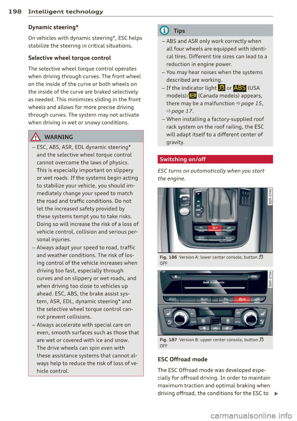
ESC turns on automatically when you start
the engine.
F ig. 1 86 Vers ion A: l owe r ce nte r con so le, butto n YJ
OFF
Fig. 1 87 Version B: upper cente r console, button YJ
OFF
ESC Offroad mode
The ESC Off road mode was developed espe
c ia lly for offroad driving . In o rder to maintain
max imum trac tion and optimal b raking when
driv ing offroad, the cond it ions for the ESC to
IJII,