AUDI Q5 2015 Owner's Manual
Manufacturer: AUDI, Model Year: 2015, Model line: Q5, Model: AUDI Q5 2015Pages: 302, PDF Size: 75.01 MB
Page 21 of 302
M N
co
a:
co
,...., \!) ..,.,
N ..,., ,....,
A WARNING ,~
- If the 1111 (USA models)/ . (Canada mod
els) brake system indicator light turns on to
gether with the ABS and ESC indicator
lights, the ABS/ESC regulating function may
have failed. Functions that stabilize the ve
hicle are no longer available. This could
cause the vehicle to swerve and increase the
risk of sliding. Drive carefully to the nearest
authorized Audi dealer or other qualified
workshop and have the malfunction correct
ed.
- If the brake warning/indicator light does
not go out after a few seconds and the park
ing brake is released, or lights up while you
are driving, the fluid level in the brake fluid reservoir is too low. If you believe that it is
safe to do so, proceed immediately at low
speed to the nearest authorized Audi dealer
or qualified repair facility and have the
brake system inspected.
- Always keep in mind that after several brake
applications, you will need greater pressure
on the brake pedal to stop your vehicle. Do
not rely on strained brakes to respond with
maximum stopping power in critical situa
tions. You must allow for increased braking
distances. The extra distance used up by
fading brakes could lead to an accident.
Instruments and indicator lights
19
Page 22 of 302
Driver information system
Driver information
system
Introduction
General notes
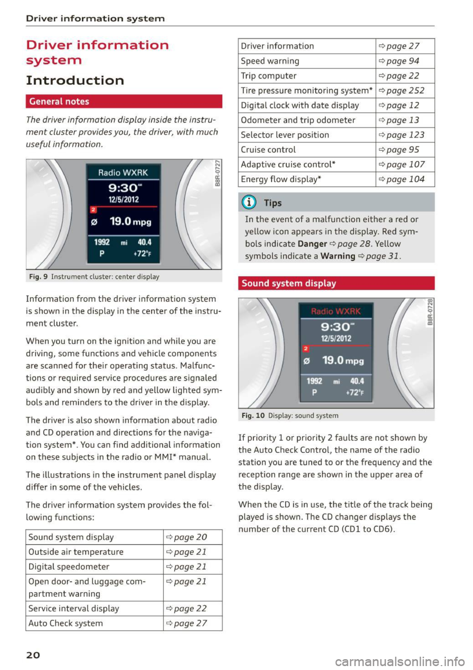
The driver information display inside the instru
ment cluster provides you, the driver, with much
useful information .
Fig. 9 Instrument cluster: center display
Information from the driver information system
is shown in the display in the center of the instru
ment cluster .
When you turn on the ignition and while you are driving, some functions and vehicle components
are scanned for their operating status. Malfunc
tions or required service procedures are s ignaled
aud ibly and shown by red and yellow lighted sym
bols and reminders to the driver in the display.
The driver is also shown information about radio
and CD operation and directions for the nav iga
tion system* . You can find additional informat ion
on these subjects in the radio or
MMI" manual.
The illustrations in the instrument panel display
differ in some of the vehicles.
The driver information system provides the fol
lowing functions :
Sound system disp lay ¢
page20
Outside air temperature ¢page 21
Digital speedometer ¢
page 21
Open door- and luggage com- ¢page 21
partment warning
Service interval display ¢page22
Auto Check system ¢page27
20
Driver information ¢
page 27
Speed warn ing ¢
page94
Trip computer ¢page22
Tire pressure monitoring system* ¢page
252
Digital clock with date display ¢page 12
Odometer and trip odometer ¢
page 13
Selector lever position r::>page 123
Cruise control ¢
page95
Adapt ive cruise control* ¢page 107
Energy flow disp lay* r::>
page 104
@ Tips
In the event of a malfunction either a red or
ye llow icon appears in the display. Red sym
bols indicate
Danger¢ page 28. Yellow
symbols ind icate a
Warning r::>page 31.
Sound system display
Fig. 10 D isplay: sou nd system
If priority 1 or priority 2 faults are not shown by
the Auto Check Contro l, the name of the radio
station you are tuned to or the frequency and the
reception range are shown in the upper area of
the d isplay .
When the CD is in use, the tit le of the track being
played is shown. The CO changer d isplays the
number of the current CO (CDl to CD6).
Page 23 of 302
M N
co ~ co
rl I.O
"' N
"' rl
Outside temperature display
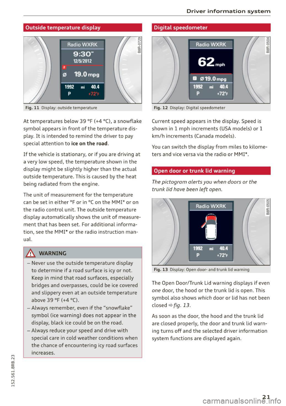
Fig. 11 Display: outside temperature
~ ,.._
9 a:
lll
At temperatures below 39 °F (+4 °C), a snowf lake
symbol appears in front of the temperature dis
play.
It is intended to rem ind the driver to pay
specia l attent ion to
ic e on the r oad .
If the vehicle is stationary, or if you are driving at
a very low speed, the temperature shown in the
d isplay m ight be slightly higher than the actual
outside temperature. This is caused by the heat be ing radiated from the eng ine.
The unit of measurement for the temperature
can be set in either °For in °Con the
MMI* or on
the radio control unit. The outs ide temperature
d isp lay automatically shows the unit of meas ure
ment that has been set. For add itional info rma
tion, see the
MMI * or the radio instruction man
ua l.
_& WARNING
-Never use the outside temperature d isp lay
to determine if a road surface is icy or not.
Keep in m ind that road surfaces, especially
br idges and overpasses, could be ice covered
and slippery even at an outs ide temperature
above 39 °F (+4 °C).
- Always remember, even if the "snowflake"
symbol ( ice warn ing) does not appear in the
display, black ice could be on the road.
-Always reduce your speed and dr ive with
special care in cold weather conditions when
the chance of encounteri ng icy road surfaces
in creases.
Dr iver inform atio n sy stem
Digital speedometer
Fig. 12 Display: Digital speedometer
Current speed appears in the display. Speed is
shown in
1 mph increme nts (USA models) or 1
km/h increments (Canada models).
You can switch the display from miles to kilome
ters and vice versa via the radio or
MMI*.
Open door or trunk lid warning
The pictogram alerts you when doors or the
trunk lid have been left open.
Fig. 13 Display: Open door· a nd trunk lid wa rning
~.., 0 .,, 0 er. 0) m
The Open Door/Trunk L id war ning displays if even
one doo r, the hood or the t runk lid is open. This
symbol a lso shows
which door or lid has no t been
closed
~fig. 13.
As soon as the doo r, the hood and the trun k lid
are closed properly, the door and trunk lid warn
ing turns off and the selected driver information
system f unctions are displayed aga in .
21
Page 24 of 302
Drive r in formation syste m
Service interval display
The service interval display reminds you when
your next service is due.
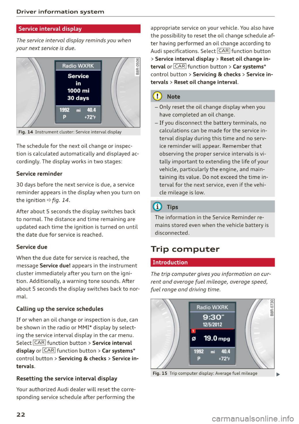
Fig . 14 Instrument cluste r: Serv ice inte rva l display
The sched ule for the next oil change or inspec
tion is calculated automatically and displayed ac cording ly . The display works in two stages :
Service remind er
30 days before the next service is due, a serv ice
reminder appea rs in the display when you tu rn on
the ignition
i=:> fig. 14.
Afte r about 5 seconds the d isplay switches back
to normal. The dis tance and time rema ining are
updated each time the ignition is turned on unti l
the date due for serv ice is reached .
Service due
When the due date for service is reached, the
message
Ser vice d ue! appears in the instrument
cluste r immediately after you tu rn on the igni
tion. Additionally, a warning tone so unds. After
about 5 seconds the disp lay switches back to nor
mal.
Calling up the service schedule s
If or when an oil change o r inspection is due, ca n
be shown in the radio or
MM I* display by se lect
ing the service interva l display in the car menu.
Select ICARI function button
> Se rvice inte rv a l
di spl ay
or I CAR I function button > C ar sys tems*
control button > Serv icin g & check s > Ser vic e in
ter val s.
Res etting the ser vice int erv al display
Your authorized Audi dealer wi ll reset the corre
sponding service schedu le after performing the
22
appropriate service on your vehicle . You also have
the possibility to reset the oil change schedule af
ter having performed an oi l change according to
Audi spec ifications. Select
I CAR I function button
> S er vice inter val di spla y> Reset o il change in
ter val
or! CAR I function button> Ca r sy ste ms *
control button > Ser vicing & check s > Service in
t e rv al s
> Reset oil change int erval.
(D Note
- Only reset the oil change display when you
have completed an oil change .
-If you disconnect the battery terminals, no
calculations can be made for the serv ice in
terval disp lay dur ing th is time and no serv
ice remi nder w ill appea r. Remember that
observing the proper service intervals is v i
tally important to extend ing the life of yo ur
vehicle, particularly the engine, and main
ta ining its value . Do not exceed the time in
terval for the next service, even if the veh i
cle mileage is low.
(D Tips
The information in the Service Reminder re mains stored even when the vehicle battery is
disconnected.
Trip computer
Introduction
The trip computer gives you information on cur
rent and average fuel mileage , average speed,
fuel range and driving time .
Fig. 15 Trip computer d isp lay: Average fue l m ileage
Page 25 of 302

M N
co
a:
co
,...., \!) 1.1'1
N 1.1'1 ,....,
The following information is continuo usly evalu
ated by the trip computer and can be displayed
seq uent ia lly in the instrument cl uster display:
Fue l range
The estimated cruising range in m iles (km) ap
pears in t he disp lay . This te lls you how fa r your
vehicle wi ll be able to travel on the current tank
of fuel and with the same driving style. The dis
p lay changes in increments of 5 mi les (10 km) .
Average fuel mileage
The average fue l economy in M PG (l/ 100 km)
since yo u last cleared the memory appears in this
disp lay . You can use this display to adjust your
driving technique to achieve a desired mileage .
Current fuel mileage
The instantaneous fuel consumption in miles per
ga llon (l/100 km) is shown in this display . Yo u
can use th is disp lay to adjust your d riving techni
q ue to achieve a desi red mileage .
F ue l consumption is reca lcula ted at interva ls of
33 yards (30 meters). This d isplay switches to
ga llons/ho ur (lite rs/hour) when the vehicle is not
moving.
Average speed
The average speed in mph (km/h) since the last
time the display was reset appears in the display.
Elapsed time
T he length of time that you have been driving
since you last reset the memory appears in this
d isp lay .
Distance
The distance that has been covered s ince the last
t ime the memory was cleared appears in the dis
p lay .
@ Tips
-Fuel consumptions (average and current),
range and speed are disp layed in metric
units on Canadian models .
- All stored va lues w ill be lost if the veh icle
battery is disconnected.
Dri ver information s ystem
Memories
The trip computer is equipped with two fully au
tomatic memories as well as an efficiency pro
gram* .
Fig. 1 6 Trip comput er dis play: m emory lev el 1
You can switch between the trip computer 1 and
2 and the effici ency program* by pressing the
I RESET I button @ c> page 24, fig. 17 .
You can tell wh ich memory leve l is cu rrently ac
t ive by the number or the sign in the display
c> fig. 16. The data from the single-trip memory
(memory level 1) is being displayed if a
D ap
pears in the display. If a fJ is shown, then the da
ta from the total-trip memory is being d isplayed
(memory level 2) . The fue l pump nozzle
iii ind i
cates the eff ic iency p rog ram *
c> page 25 .
Single-trip memory (Trip compute r 1)
The sing le-tr ip memory stores the tr ip info rma
t ion from the time the ignition is turned on until
i t is turned off . If the trip is continued
within 2
hours
from the t ime the ignition was turned off,
the new data will be included in the calcu lation of
t h e curren t trip informat io n. If the trip is inter
rupted for
more than 2 hour s the memory is re
set automatically .
Total-trip memory (Trip computer 2)
Unlike the single-tr ip memo ry, the total-trip
memo ry is not reset automat ica lly. This permits
you to eva luate yo ur dr iv ing da ta fo r the ent ire
per iod between m anual resets.
Efficiency program*
T he efficiency program ca n he lp you to use less
fuel
c> page 25 .
23
Page 26 of 302
Driver information system
Operation
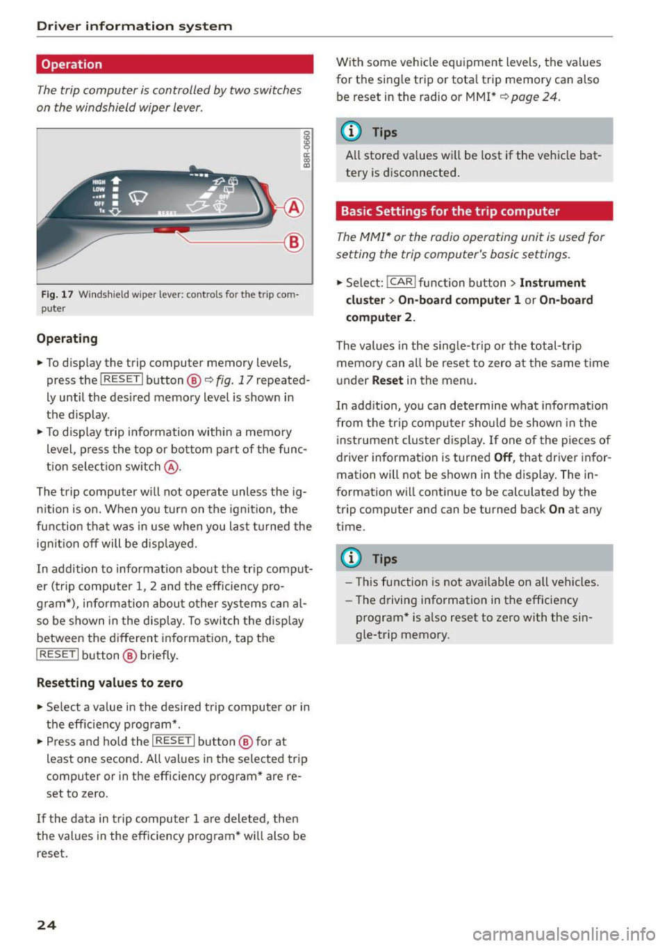
The trip computer is controlled by two switches
on the windshield wiper lever.
g
~ a: (0 a,
~-- @
Fig. 17 Windshield w iper lever: controls fo r the trip co m
puter
Operating
.. To display the trip computer memory levels,
press the
I RESET I button ®<=> fig. 17 repeated·
Ly until the desired memory level is shown in
the display.
.. To display trip information within a memory
level , press the top or bottom part of the func
tion selection switch @.
The trip computer will not operate unless the ig·
nition is on. When you turn on the ignition , the
f unc tion that was in use when you last turned the
ignit ion off will be displayed.
In addition to information about the trip comput
er (trip computer 1, 2 and the efficiency pro
g ram*), information about other systems can al
so be shown in the display. To switch the display
between the different information, tap the
I RESET I button® briefly.
Resetting values to zero
.. Select a value in the desired trip computer or in
the efficiency program* .
.,. Press and hold the
I RESE T I button @ for at
least one second. All values in the selected trip
computer or in the efficiency program* are re
set to zero .
If the data in trip computer 1 are deleted, then
the values in the efficiency program * wi ll also be
reset.
24
With some vehicle equipment levels, the values
for the single trip or tota l trip memory can also
be reset in the radio or MMI*
¢page 24.
(D Tips
All stored values wi ll be lost if the vehicle bat
tery is disconnected.
Basic Settings for the trip computer
The MMI* or the radio operating unit is used for
setting the trip computer's basic settings .
.. Select: !CAR ! function button > Instrument
cluster > On-board computer 1
or On-board
computer
2.
The values in the single-trip or the total-trip
memory can all be reset to zero at the same time
under
Reset in the menu.
In add ition, you can determine wha t infor mation
from the trip computer should be shown in the
i nst rument cluster display. If one of the pieces of
driver information is turned
Off, that driver infor
mation will not be shown in the display. The in
formation will continue to be calculated by the
trip computer and can be turned back
On at any
time .
(D Tips
-Th is function is not available on all vehicles.
- Th e driving information in the efficiency
program* is also reset to zero with the sin
gle-trip memory.
Page 27 of 302

M N
co ~ co
rl I.O
"' N
"' rl
Efficiency program
Description
Applies to vehicles: with efficiency program
Fig. 18 Display : efficiency program
" Press the I RESET I button @¢ page 24, fig. 17
repeatedly until the efficiency program appears
in the d isplay.
The efficiency program can help you to use less
fuel. It evaluates driving information in reference
to fuel consumption and shows other equipment in fluencing consumption. Fuel economy messag
es¢
page 25 provide t ips fo r eff icient driving.
The efficiency program uses distance and con
sumption data from trip computer
1. If the data
are deleted in the efficiency program, those val
ues are also reset in trip computer
1.
Other equipment
A ppl ies to vehicles: with efficiency program
Fig. 19 Display: other equ ipment
" In the efficiency program, press the function
selection switch¢
page 24, fig. 17@ repeat
edly until the other equipment appears in the
display.
Dri ver information system
Other equipment that is currently affecting fuel
consumption is listed in the efficiency program.
The display shows up to three other items of
equipment @. The equipment using the most
fuel is listed first. If more than three items using
fuel are switched on, the equipment that is cur rently using the most fuel is displayed.
A scale @also shows the current total consump
tion of all other equipment.
Fuel economy messages
Applies to vehicles: wit h efficiency program
Fig. 20 Display: fuel economy message
Fuel economy messages are displayed when fue l
consumption is increased by certain conditions. If
you follow these fuel economy messages, you can reduce your vehicle's consumption of fuel. The
messages appear automatically and are only dis
played in the efficiency program . The fuel econo
my messages turn off automatically after a cer
tain period of time.
" To turn a fuel economy message off immediate
ly after it appears, press the
I RESET ! button
¢ page 24, fig. 17@, or
" Press the func tion select io n switch ¢
page 24,
fig. 17@.
(D Tips
-Once you have turned a fuel economy mes
sage off, it will only appear again after you
turn the ignition on again.
- T he fuel economy messages are not dis
played in every instance, but rather in inter
vals over a period of time .
25
Page 28 of 302
Driver information system
On Board Diagnostic
System (OBD)
Malfunction Indicator Lamp (MIL)
The Malfunction Indicator Lamp (MIL) ¢• in the
instrument cluster
c:::> page 14, fig. 8 is part of the
On-Board Diagnostic (OBD II) system.
The warning/indicator light i lluminates when the
ignition is switched on and goes out after the en
gine starts and the idle has stabilized. This indi
cates that the MIL is working properly.
If the light does not go out after the engine is
started, or illuminates while you are driving, a
malfunction may exist in the engine system. If
the light illuminates, the catalytic converter
could be damaged.
Continue driving
with reduced power (avoiding
sustained high speeds and/or rapid acce lerations)
and have the condition corrected. Contact your
authorized Audi dealer.
I f the light illuminates, the electronic speed lim
iter may also be malfunctioning. For more infor
mation
c::> page 26, Electronic speed limiter.
An improperly closed fuel filler cap may also
cause the MIL light to illuminate (only vehicles
with gasoline engine)
c:::> page 216.
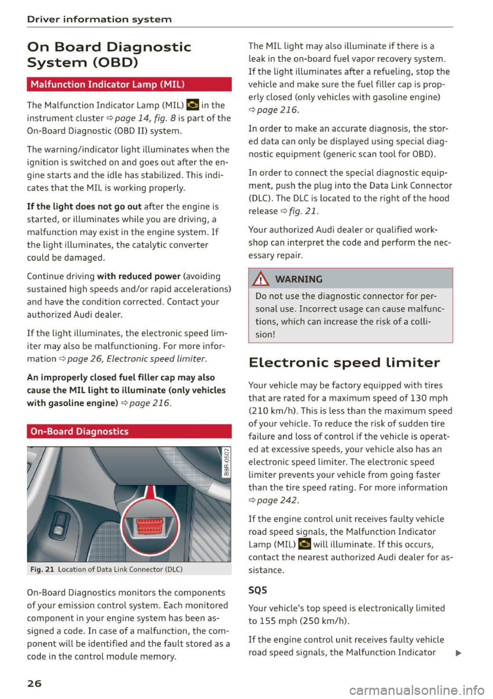
On-Board Diagnostics
F ig . 21 Locat ion of Data link Connector (DLC)
On-Board Diagnostics monitors the components
of yo ur emission control system. Each monitored
component in your engine system has been as
signed a code . In case of a malfunction, the com
ponent will be identified and the fault stored as a
code in the control module memory.
26
The MIL light may also illuminate if there is a
l eak in the on-board fuel vapor recovery system.
If the light illuminates after a refueling, stop the
vehicle and make sure the fuel filler cap is prop
erly closed (only vehicles with gasoline engine)
c::> page 216.
In order to make an accurate diagnosis, the stor
ed data can only be displayed using specia l diag
nostic equipment (generic scan tool for OBD).
In order to connect the specia l diagnostic equip
ment, push the plug into the Data Link Connector
(DLC) . The DLC is located to the right of the hood
release
c::> fig. 21.
Your authorized Audi dealer or qualified work shop can interpret the code and perform the nec
essary repair .
A WARNING
Do not use the diagnostic connector for per
sonal use. Incorrect usage can cause malfunc
tions, which can increase the r isk of a coll i
sion!
Electronic speed limiter
Your vehicle may be factory equ ipped with tires
that are rated for a maximum speed of 130 mph
(210 km/h) . Th is is less than the max imum speed
of your veh icle. To reduce the risk of sudden tire
failure and loss of control if the vehicle is ope rat
ed at excessive speeds, your vehicle also has an
electronic speed limiter . The electronic speed
limiter prevents your vehicle from going faster
than the tire speed rating. For more information
c::> page 242.
If the engine contro l unit receives faulty vehicle
road speed signals, the Malfunction Indicator
Lamp (MIL) ¢•will illuminate. If this occurs,
contact the nearest authorized Audi dealer for as
sistance.
SQS
Your vehicle's top speed is electronically limited
to 155 mph (250 km/h).
If the engine contro l unit receives faulty vehicle
road speed s ignals, the Malfunction Ind icator ..,_
Page 29 of 302
M N
co ~ co
rl I.O
"' N
"' rl
Lamp (MIL) ¢..ffi will il luminate. If this occurs,
contact the nea rest authorized Audi dea ler for as
sistance.
.&_ WARNING
Always observe the posted speed limits and adjust your speed to suit prevailing road, traf
fic and weather cond it ions . Never drive your
vehicle faster than the maximum speed rating
of the tires installed .
Auto Check Control
Introduction
The Auto-Check control monitors the function of
certain vehicle features and components .
It sim
ply makes sure these features and components
are working properly . The Auto-Check control
works as long as the ignition is on, as well as
whenever the veh icle is driven .
-
If a component is malfunctioning or if the need
for an urgent repair has been detected, this will appear in the instrument cluster display . You w ill
also hear an audible warning tone . The displays
are color coded in either red or ye llow depending
on their level of prior ity.
A red symbol means
Danger , a yellow symbol in
dicates
Warning . In certain situations, informa
tion message for the dr iver appear in addition to
the red and yellow symbols.
Note about automatic transmission
The Auto-Check Control will automat ically per
form a test each time you switch o n the ignition .
With the selector lever in P or N, the following
message appears in the display :
When stationary apply brake pedal while select
ing gear
When you select a different gear (for example: R,
D, etc.), the message will disappear and the Au
to -Check function is d isplayed.
If there is a malfunction, then the malfunction
message will appear about 15 seconds after you
start the vehicle. At the same time you will hear a
warning tone.
Dri ver information system
Dr iver information messages
Driver information messages are shown in the in
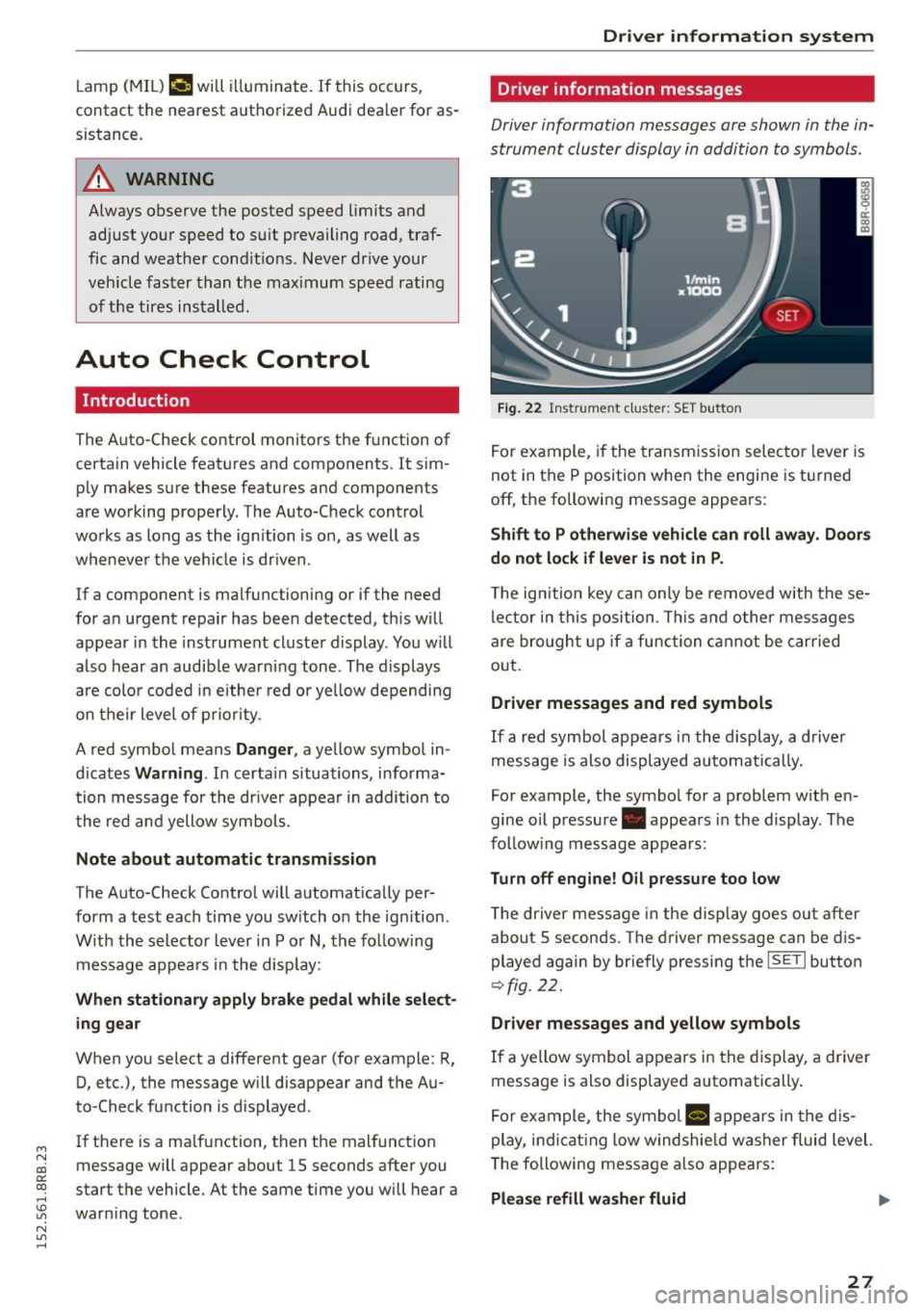
strument cluster display in addition to symbols .
Fig. 22 Inst rume nt clust er: SET button
For example, if the transmission selector lever is
not in the P position when the engine is turned
off, the following message appears :
Shift to P otherwise vehicle can roll away. Doors
do not lock if lever is not in P .
The ign ition key can only be removed w ith these
lector in this position . This and other messages
are bro ught up if a function cannot be carried
out .
Driver messages and red symbols
If a red symbol appears in the display, a driver
message is also displayed automatically.
For example, the symbol for a problem w ith en
gine oil pressure . appears in the display . The
fo llow ing message appears:
Turn off engine! O il pressure too low
T he driver message in the display goes out after
about S seconds . The dr iver message can be dis
played again by briefly press ing the
ISETI button
9 fig . 22.
Driver messages and yellow symbols
If a yellow symbol appears in the display, a driver
message is also displayed automatically .
For example, the symbol
Ill appears in the dis
play, indicat ing low windshie ld washer fluid level.
The following message also appears :
Please refill washer fluid ..,_
27
Page 30 of 302

Driver inform ation system
The driver message disappears after a few sec
onds. The driver m essage can be displayed again
by briefly pressing the
I SETI button.
Red symbols
F ig. 23 Display: Dang er symbol
W ith a priority 1 malfunction, a red symbol ap
pears in the upper center area of the disp lay
0 ~
"' 0 ci: a, al
¢ fig . 23. A driver message appears as well to ex
p lain the ma lfunction in more detail. When this
symbo l appears,
three warning tones sound in
success ion . The symbol continues to flash until
the fault has been corrected .
If
several pr iority 1 malfunctions are present, the
symbo ls appear in succession and remain for
about 2 seconds.
The driver warning goes out after about 5 sec
onds, but it can be brought up again at any time by pressing the
! SET ! button ¢ page 2 7.
28
Alternator fa i Lu re
¢ page28
Electromechanica l steering
¢ page 195
USA m odels : Brake system
malfunct ion
¢ page28
Canada models: Brake system
malfunct ion
¢page28
E ng ine coolant leve l too low/
engine coolant temperature
too high
¢ page29
Eng ine oi l pressure too low
¢ page30
Refi ll eng ine oi l now
¢ page 30
Refill Ad Blue*
¢ page 218
AdBlue malfunction*
¢ page 218
Steering malfunction
¢page30
Ign it ion lock malfunction
¢ page 30
Hybrid dr ive*
¢ page 100, ¢ page 1 OS
0 Alternator malfunction
If the . symbo l in the instr ument pane l display
flashes, then there is a malf unction in the alter
nator or the vehicle electronics . A warning to t he
driver will appear, too . The driver warning goes
out after about 5 seconds, but it can be brought up at any t ime by pressing the
ISE TI button again.
Usually, yo u can sti ll drive to the next dealership.
Turn off a ll but the most necessary electrica l con
sumers, s ince these dra in the veh icle 's battery .
CJ) Note
If the . warning symbo l (coo lant system
malfunction) also lights up on the instrument
panel during the trip
¢ page 29, then you
have to stop immediately and turn off the en
gine . The coolant pump is not working a ny
more -da nger of damage to the eng ine !
BRAKE /C(D ) Brake system malfunction
A malfunction in the brake sy stem mus t be re
paired as soon as possible .
If the warning/indicator light 1111 (USA mod
els)/ . (Canada models) in the instrument clus
ter flashes, there is a brake system malfunction .
A d river message appea rs as well to expla in the
malfunction in more detail. The d river war ning
goes out after about S seconds, but it can be
brought up a t any time by pressing the
ISE TI but-
ton again. .,.