fuel pressure AUDI Q5 2017 Owners Manual
[x] Cancel search | Manufacturer: AUDI, Model Year: 2017, Model line: Q5, Model: AUDI Q5 2017Pages: 296, PDF Size: 74.43 MB
Page 5 of 296
CD
CD
.... N ,-... N ..... 0 0 C<'. 00
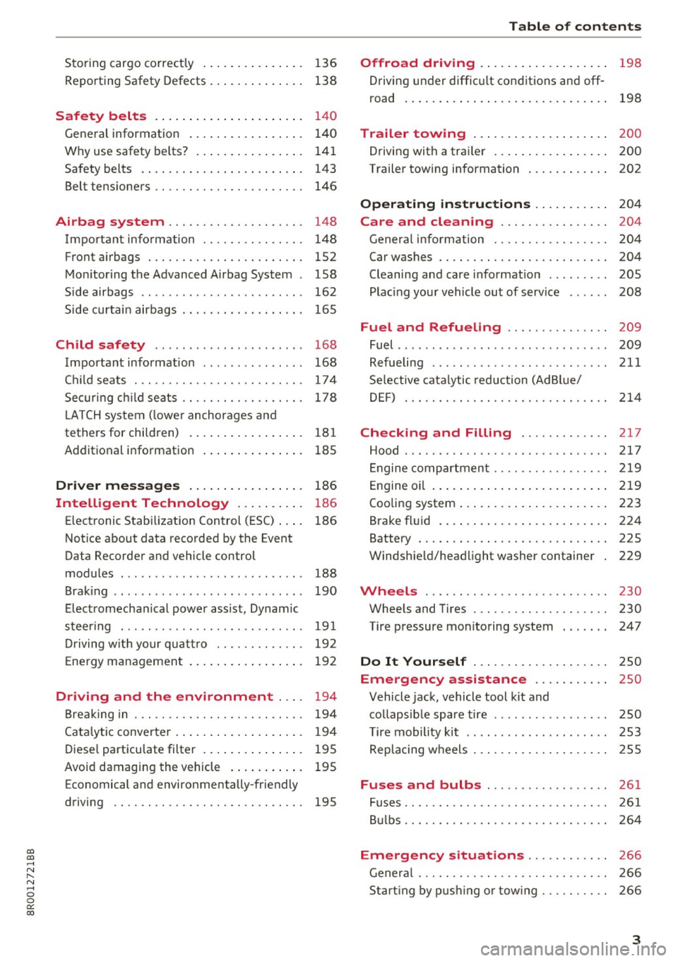
Storing cargo correctly . . . . . . . . . . . . . . . 136
R epo rting Safety Defects . . . . . . . . . . . . . . 138
Safety belts . . . . . . . . . . . . . . . . . . . . . . 14 0
General information . . . . . . . . . . . . . . . . . 140
Why use safety belts? . . . . . . . . . . . . . . . . 141
Safety belts . . . . . . . . . . . . . . . . . . . . . . . . 143
Belt tensioners . . . . . . . . . . . . . . . . . . . . . . 146
Airbag system . . . . . . . . . . . . . . . . . . . . 148
Important information . . . . . . . . . . . . . . . 148
Front airbags . . . . . . . . . . . . . . . . . . . . . . . 1S2
Monitoring the Advanced Airbag System . 158
Side airbags . . . . . . . . . . . . . . . . . . . . . . . . 162
Side curtain airbags . . . . . . . . . . . . . . . . . . 165
Child safety . . . . . . . . . . . . . . . . . . . . . . 168
Important information . . . . . . . . . . . . . . . 168
Ch ild seats . . . . . . . . . . . . . . . . . . . . . . . . . 174
S ecur ing ch ild seats . . . . . . . . . . . . . . . . . . 178
L ATCH system (lower anchorages and
tethers for chi ldren) . . . . . . . . . . . . . . . . . 181
Additional in fo rma tion
185
Driver messages . . . . . . . . . . . . . . . . . 186
Intelligent Technology . . . . . . . . . . 186
Elect ronic Stabilization Control (ESC) . . . . 186
Notice about data recorded by the Event
Data Recorder and vehicle control
modules . . . . . . . . . . . . . . . . . . . . . . . . . . . 188
B rak ing . . . . . . . . . . . . . . . . . . . . . . . . . . . . 190
E lect romechanical power assist, Dynamic
steering . . . . . . . . . . . . . . . . . . . . . . . . . . . 191
Dri ving with your quattro . . . . . . . . . . . . . 192
En erg y management . . . . . . . . . . . . . . . . . 192
Driving and the environment . . . . 194
Br eak ing in . . . . . . . . . . . . . . . . . . . . . . . . . 194
Catalytic converter . . . . . . . . . . . . . . . . . . . 194
Di ese l particulate filter . . . . . . . . . . . . . . . 195
Avoid damaging the vehicle . . . . . . . . . . . 195
Economical and environmentally-friendly
driving . . . . . . . . . . . . . . . . . . . . . . . . . . . . 195
Table of contents
Offroad driving . . . . . . . . . . . . . . . . . . .
198
Driving under difficult conditions and off-
ro ad . . . . . . . . . . . . . . . . . . . . . . . . . . . . . . 198
Trailer towing . . . . . . . . . . . . . . . . . . . . 200
Driving with a traile r . . . . . . . . . . . . . . . . . 200
Trailer towing information . . . . . . . . . . . . 202
Operating instructions . . . . . . . . . . . 204
Care and cleaning . . . . . . . . . . . . . . . . 204
Genera l information . . . . . . . . . . . . . . . . . 204
Car washes . . . . . . . . . . . . . . . . . . . . . . . . . 204
Cleaning and care information . . . . . . . . . 205
Plac ing your vehicle out of service . . . . . . 208
Fuel and Refueling . . . . . . . . . . . . . . . 209
Fuel .. .. .. .. .. .. .. ... .. ..... ... .. .. 209
Refueling ... .. .. .. .... .. ... .... .. .. 211
Selective catalytic reduct ion (Ad Blu e/
DEF) . . . . . . . . . . . . . . . . . . . . . . . . . . . . . . 214
Checking and Filling ........... .. 2 17
Hood ..... .. .. .. ................. .. 217
Eng ine compartm ent . . . . . . . . . . . . . . . . . 219
Eng ine oil . . . . . . . . . . . . . . . . . . . . . . . . . . 219
Cooling system . . . . . . . . . . . . . . . . . . . . . . 223
Brake fluid . . . . . . . . . . . . . . . . . . . . . . . . . 224
Battery . . . . . . . . . . . . . . . . . . . . . . . . . . . . 225
Windshield/headlight washer container
229
Wheels ........................... 230
Wheels and Tires . . . . . . . . . . . . . . . . . . . . 230
Tire pressure monitoring system 247
Do It Yourself . . . . . . . . . . . . . . . . . . . . 250
Emergency assistance . . . . . . . . . . . 250
Vehicle jack, vehicle tool kit and
collapsible spare tire . . . . . . . . . . . . . . . . . 250
T ire mobility kit . . . . . . . . . . . . . . . . . . . . . 253
Replacing wheels . . . . . . . . . . . . . . . . . . . . 255
Fuses and bulbs . . . . . . . . . . . . . . . . . . 261
Fuses . . . . . . . . . . . . . . . . . . . . . . . . . . . . . . 261
Bulbs . . . . . . . . . . . . . . . . . . . . . . . . . . . . . . 264
Emergency situations . . . . . . . . . . . . 266
General . . . . . . . . . . . . . . . . . . . . . . . . . . . . 266
Starting by pushing or tow ing . . . . . . . . . . 266
3
Page 12 of 296
Instruments and indicator lights
The number of keys programmed to the vehicle is
also displayed. The display
L2 3/3 in dicates that
three keys have been programmed. This a llows
you to make sure you have received all of the keys
when you purchase a used vehicle.
For examp le, if you on ly receive two keys, you
should take those keys to your authorized Audi
dealer to have the missing key deactivated so it
cannot be used. You should also report the miss
ing key to your insurance company .
Calling up the driver information
A yellow or red symbol appears in the instrument
cluster display, usually with a driver message.
The driver message display disappears after about 5 seconds. The dr iver message can be dis
played again by briefly pressing the
ISETI button.
Setting the speed warning
By pressing the !SET ! button briefly, you can set
thresho ld
1 of the speed warning while you are
driving
c::;,page 92. By maintaining pressure on
the
! SET I button, you delete the warning thresh
old.
Digital clock with date display
Depending on the vehicle equipment level, you
may choose between the quartz clock or the
GPS
controlled clock* l!j in the radio or in the MMI* .
You can learn more about this in the MMI manual
or in the radio user's manual.
(Di Tips
-When you sw itch off the ignition or open
the driver door, the time, date, odometer
and temperature are displayed for an addi
tiona l
30 seconds.
- You can also call up the display with the
ISET I button c::;, page 9 while the ignition is
switched
off.
Fuel gauge
The fuel gauge works only when the ignition is
on.
When the needle reaches the reserve mark, the
c::;, page 30 Ii') symbol appears in the instru-
10
ment cluster display as well as the message
Please refuel. This message is meant to remind
you to
refuel.
The total tank capacity of your ve hicle is listed in
¢ page 273.
(D Note
Never run the tank completely dry! An ir regu
lar supply of fuel can cause engine misfiring
and fuel could enter into the exhaust system.
The catalytic converter could then overheat
and be damaged.
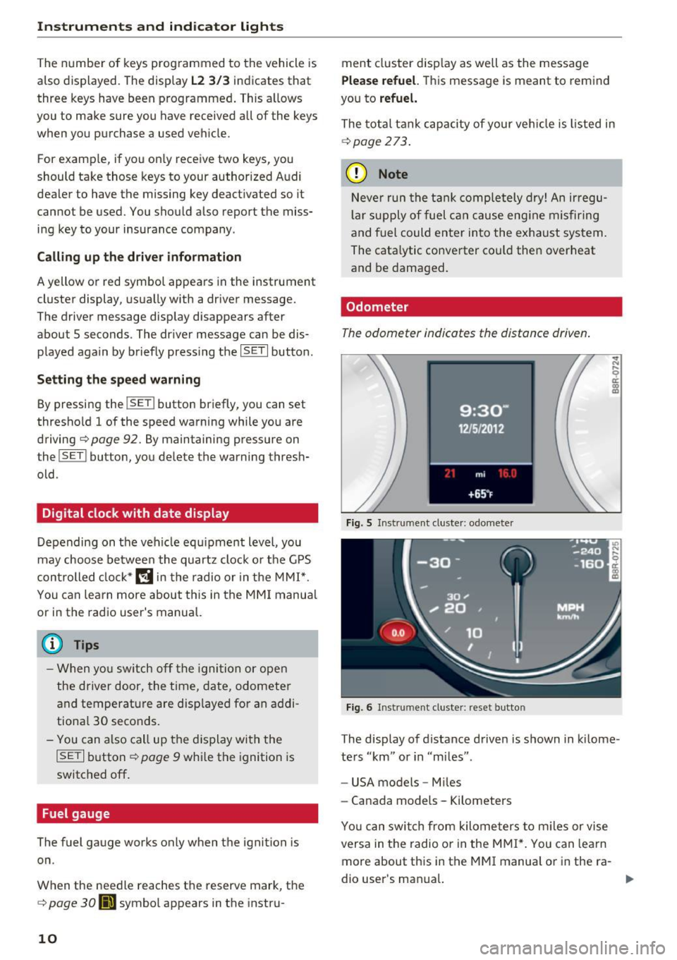
Odometer
The odometer indicates the distance driven.
Fig. 5 Instrument cluster: odometer
Fig. 6 Instrument cluster: reset button
The display of distance driven is shown in kilome
ters "km" or in "m iles".
- USA models -Miles
- Canada models - Kilometers
Yo u can switch from kilometers to miles or vise
versa in the radio o r in the MMI*. You can lea rn
more about this in the MMI manual or in the ra
dio user's man ual.
Page 29 of 296
CD
CD
.... N ,-... N .... 0 0 C<'. 00
(D Note
Do not continue d riving if the. sym bol ill u
m inates . There is a mal function in the en gine
coo ling system -you could damage your en
gi ne.
't=?: Engine oil pressure malfunction
The red engine oil pressure warning symbol re
quires immediate service or repair. Driving with a
low oil pressure indication is likely to cause se
vere engine damage .
If the . symbol on the display flashes, the en
g ine oi l pressure is too low. A d river message ap
pears as well to explain t he malfunction in mo re
deta il. Th e d river war ning goes ou t afte r abo ut 5
s econds, but it can be b ro u gh t up at any time by
p ressing the
ISET I button again.
Turn off engine! Oil pressure too low
• Stop t he ve hicle .
• Turn the eng ine
off.
• Check the eng ine oi l level ¢ page 221.
• Co ntact yo ur autho rized Aud i dea le r for assis-
tance if necessary.
Engine oil level too low
If the engine o il level is too low, add eng ine oi l
¢page 221.
Engine oil level correct
If th e sym bol. flashes even thoug h the en gin e
oil leve l is correct, p lease contact your nea rest
author ized Audi Dealer for assistance. Do not
continue dr iv ing .
Do not leave the eng ine running
idle, either .
@ Tips
- The engine oil pressure symbol. is not
an indicator for a low engine oil level. Do
not rely on it. Instead, check the oil level in
your engine at regular intervals, preferably
each time you refuel, and always before
going on a long trip.
- The yellow oil level warning indication
Ill
requires oil refill or workshop service with
out delay. Do not wait until the red oil
Driver information system
pressure warning. starts to flash before
you respond to the low oil level warning
II. By then, your engine may already have
suffered serious damage .
~ ""' Fill engine oil now
WARNING : Please add oil immediately
If the. sym bo l lights up, then t he oi l has to be
r ep le ni shed right now
¢page 221.
@-Steering malfunction
If there is a malfunction in the electronic steer
ing column lock, the steering cannot be un
locked.
If the . symbo l in the disp lay bli nks, t here is a
malfunction in t he electronic stee ring col umn
l ock. A driver message appears as we ll to exp la in
t h e malfunction i n mo re detail. The dr ive r warn
ing goes out afte r about 5 seconds , but it can be
broug ht up a t any time by press ing the
ISETI but
ton aga in.
Steering defective! Do not drive vehicle!
• Contact your nea rest a uthorized Audi dea ler .
• Do
not tow your ve hicle.
A WARNING
Your ve hicle m ust not be towed in t he event
of a ma lfunction in t he e lectron ic stee ring
col um n loc k becaus e it can not be st ee red due
to the loc ked steering . If i t is towed w ith th e
st eer ing lo cked , the re is the r isk o f an acci
d en t.
©-Ignition lock malfunction
A malfunction in the ignition lock must b e re
paired immediately .
If the . symbo l in the display b links , there is a
malfu nction in t he e lectron ic ignition lock. A d riv
er m essage a ppears as well to expla in the ma l
f unct ion in mo re det ail. The driv er warning go es
out a ft er abou t 5 se cond s, but it can b e broug ht
up at an y ti me by pressing the
!SE T! bu tt o n ag ain .
Ignition lock defective. Contact dealer! .,.
27
Page 106 of 296
Hybrid
Start-Stop function
The combustion engine is operated on ly as need
ed . Generally, the combustion engine turns off
when the vehicle is stationary and the high volt
age battery powers the electrical vehicle sys
tems.
The purpose o f automatica lly shutting the com
bustion engine off in hybrid drive mode is to save
fuel. All of the important vehicle systems, such
as steering, brakes and the A/C system, continue
to remain active. In some cases , systems may re
qu ire the combustion eng ine to continue running
when the vehicle is stationary . When dr iv ing in
congested traff ic for long per iods of t ime, the
combustion eng ine will cycle on when the veh icle
is stationary to keep the high voltage battery
charged.
Gliding
If the gas pedal is not pressed and the D posit ion
is selected, the combustion engine remains
turned off up to speeds of approximately 99 mph
(160 km/h) . Driving conservative ly like th is can
reduce fuel con5umption .
Energy recovery (recuperation)
When braking, the electric motor will act as a
generator creating e lectr ic energy that is then
sto red in the high voltage battery. This also oc
curs when the vehicle is coasting or driving down
hi ll. The combustion engine is automat ica lly
turned off in this case .
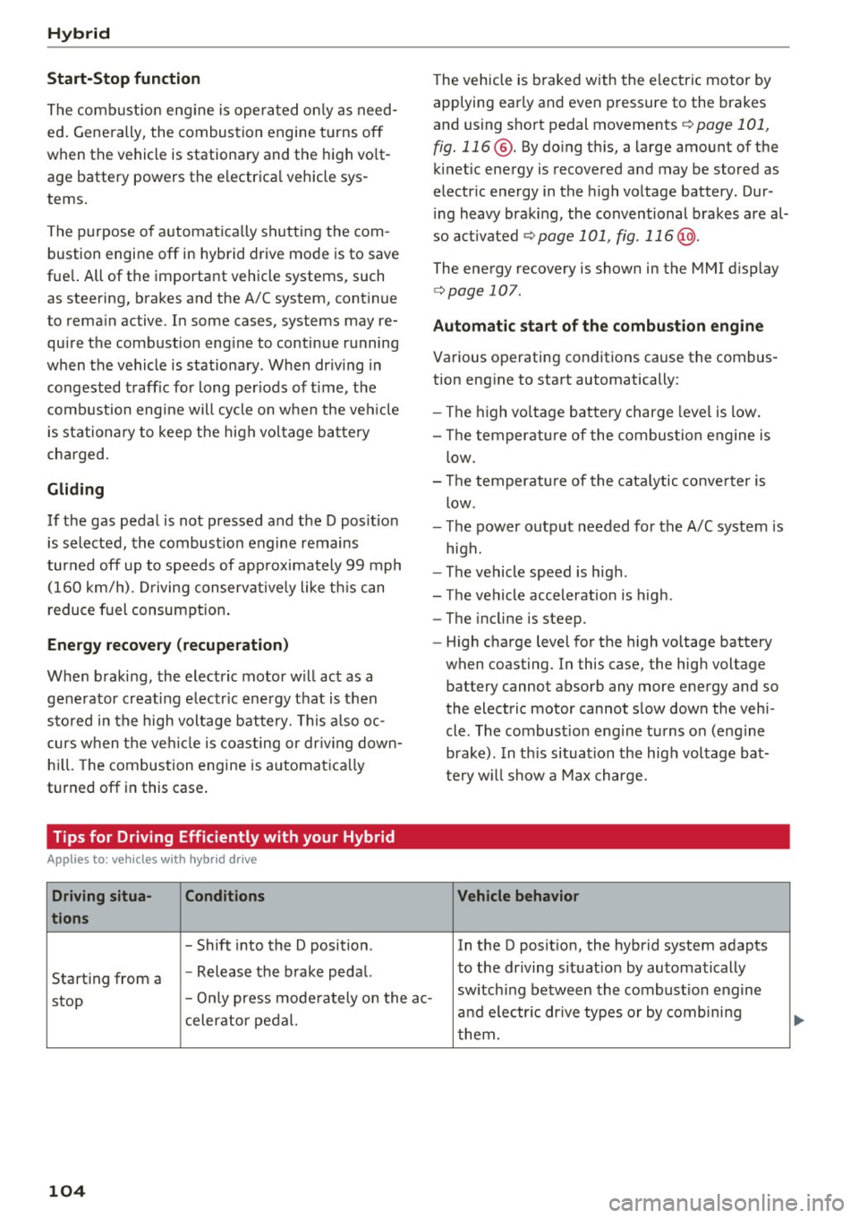
Tips for Driving Efficiently with your Hybrid
Appl ies to: ve hicles w ith hyb rid drive
Driving situa- Conditions
tions
- Shift into the D position .
Starting from a -
Release the brake pedal. The vehicle is braked with
the electric motor by
applying early and even pressure to the brakes
and using short pedal movements
¢ page 101,
fig. 116 @. By doing this, a large amount of the
kinet ic energy is recovered and may be stored as
electric energy in the high voltage battery. Dur
i ng heavy brak ing , the conventional brakes are al
so act ivated
¢ page 101, fig . 116 @.
The energy recovery is shown in the MMI display
¢page 107 .
Automatic start of the combustion engine
Various operating conditions cause the combus
tion eng ine to start automatically:
- Th e high voltage battery charge level is low.
- Th e temperature of the combustion engine is
low .
- Th e temperature of the catalytic converter is
low .
- T he power output needed for the A/C system is
high.
- The vehicle speed is high .
- The vehicle acceleration is high .
- The incline is steep .
- High charge level for the high voltage battery
when coasting. In this case, the high voltage battery cannot absorb any more energy and so
the electric motor cannot slow down the veh i
cle. The combust ion engine turns o n (engine
brake) . In this situation the high voltage bat
t ery w ill show a Max charge.
Vehicle behavior
In the D posit ion, the hybrid system adapts
to the driving situat ion by automatically
stop -
Only press moderately on the ac- sw
itch ing between the combustion engine
and e lectr ic drive types or by combining
celerator pedal.
them.
104
...
Page 223 of 296
CD
CD
.... N ,-... N .... 0 0 C<'. 00
(D Note
Driving with an insufficient oil leve l is likely to
cause severe damage to the engine .
@ Tips
-The oil pressure warning display. is not
an indicator of the oil level. Do not rely on
it. Instead , check the oil level in your en
gine at regular intervals, preferably each
time you refuel, and always before going
on a long trip.
- If yo u have the impression your engine con
sumes excessive amounts of oil, we recom
men d that you cons ult an autho riz ed Au di
dealer to hav e the ca use of your conce rn
properly diagnosed. Keep in mind that the
a ccu ra te measurement of oil consump tion
r equi re s gre at care and m ay ta ke some
time. An a uthorized Audi de aler has instr uc
tions about how to measure oil consump
tion acc urately.
Checking the engine oil level
Read oil level
"' Park your vehicle so that it is hor izonta lly level.
"' Shu t the engine off when it is at operat ing tem-
perature.
"' Switch only the ignition back on .
"' Wai t approx. two mi nutes .
"' Se lect:
I CARI funct ion button > Oil lev el. Or
"' Se le ct:
ICARI f u n ct ion butto n> Car sy stem s*
contro l button > Servicing & checks > Oil level.
"' Read the oil level in the r adio or M MI* Disp lay.
Add engine oil if the ba r of the o il level indica
tor is near "Min"
¢ page 221.
The o il level needs to be c heck ed at reg ular i nter
va ls. The bes t times to do this are w henever you
refuel and pr io r to long trips .
D epending on t he way t he ve hicle is dr iven and
the operat ing cond itions, o il cons umption can be
up to a 1 /2 q uart per 600 m iles ( O.S li ter per
1,000 km) . Cons umption may be hig he r within
the first 3,000 miles (5,000 km).
Checking and Filling
{!) Tips
The oil leve l indicator in t he radio o r MMI*
D isp lay is only an i nfo rmation disp lay. If the
oi l level is too low, a minimum o il wa rning ap
pears in the instrument cl uster. Add oil
¢ page 221. If the hood has been o pened ,
t he cur rent oi l level is show n in the inst ru
ment clust er the n ext time t he igni tion is
swi tched o n.
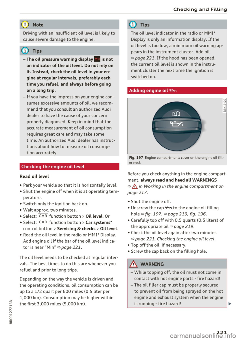
Adding engine oil~
Fig. 197 En gin e co mpa rt m ent: cove r o n th e eng ine o il fill
e r neck
Befo re yo u check any thing in the engine compa rt
ment,
always read and heed all WARNINGS
¢ A in Working in the engine compartment on
page 217.
"' Shu t the eng ine off .
"' Unscrew the cap
9=;1: to the engine oil f illing
hole
¢ fig.197, ¢page 219, fig.196 .
"'Carefully top off with 0.5 quarts (0. 5 liters) of
the appropriate oil¢
page 219.
"' Check the oil level again after two minutes
~ page 221, Checking the engine oil level .
"'Top off th e oil, if nec essary.
"' Scr ew the cap ba ck on the fi lling hole.
_&. WARNING
- Whi le toppin g off , the o il mus t no t come in
con tact w ith ho t en gine parts -fir e hazard !
- Th e oi l filler c ap must b e pr oper ly sec ure d
t o p reve nt o il from being spraye d on t he ho t
e ngine an d exha ust system whe n the engi ne
-
is run ning -fi re hazard ! Ill>-
221
Page 235 of 296
Bead separa tion
means a breakdown of the bond
between components in the bead.
Cord
means the strands forming the
plies in the tire .
Cold tire inflation pressure
means the tire pressure recom
mended by the vehicle manufac
turer for a tire of a designated size that has not been driven for
more than a couple of miles (kilo
meters) at low speeds in the
three hour period before the tire
pressure is measured or adjusted .
Curb weight
means the weight of a motor ve
hicle with standard equipment in
cluding the maximum capac ity of
fuel, oi l, and coolant, a ir condi
tioning and add itional weight of
optional equipment.
E xtra load tire
means a tire designed to operate
at higher loads and at h igher in
flation pressures than the corre sponding standard tire. Extra load
tires may be identified as "XL",
g; "xl", "E XTRA LOAD" , or "RF" on
-~ the sidewal l.
-0 0 0: a:,
Wheels
Gross Axle Weight Rating
(" GAWR")
means the load-carrying capacity
of a single axle system, measured
at the tire -ground interfaces.
Gross Vehicle Weight Rating
(" GVWR ")
means the max imum total loaded
weight of the vehicle.
Groove
means the space between two ad
jacent tread ribs .
Load rating (code)
means the maxim um load that a
tire is rated to carry for a given in
flat ion pressure . You may not f ind
this informat ion on all tires be
cause it is not required by law.
Maximum load rating
means the load rating for a tire at
the maximum permissible infla
tion pressure for that tire .
Maximum loaded vehicle
weight
means the sum of:
(a) Curb weight
(b) Accessory weight
(c) Vehicle capacity we ight , and
(d) Production options we ight
233
Page 243 of 296
a,
a,
-N r-N
-0 0 0: a:,
and follow the important safe
ty precautions inc:::>
page 242,
Tires and vehicle load limits .
-The tire must flex more if the
tire pressure is too low or if
the vehicle speed or load are
too high . This heats the tire up
too much. This increases the risk of an accident because it
can cause the tire to burst and result in loss of vehicle con
trol.
- Incorrect tire pressure in
creases tire wear and has a negative effect on driving and
Tire pressure table
Please note that the information
contained in the following table
was correct at the time of print ing, and the information is sub
ject to change . If there are differ
ences between this information
and the tire pressures specified
on the label on the driver's side B
pillar, always follow the specifica
tion on the B-pillar label
c:::> page 240, fig. 204.
Wheels
braking behavior, which in
creases the risk of an accident.
Replace lost valve caps to re
duce the risk of damage to the
tire valves.
Tire pressure that is too low in creases fuel consumption.
Audi recommends using the
tire pressure specified for a
normal load
c:::> table on
page 242
or for a full load
when the vehicle is partially
loaded .
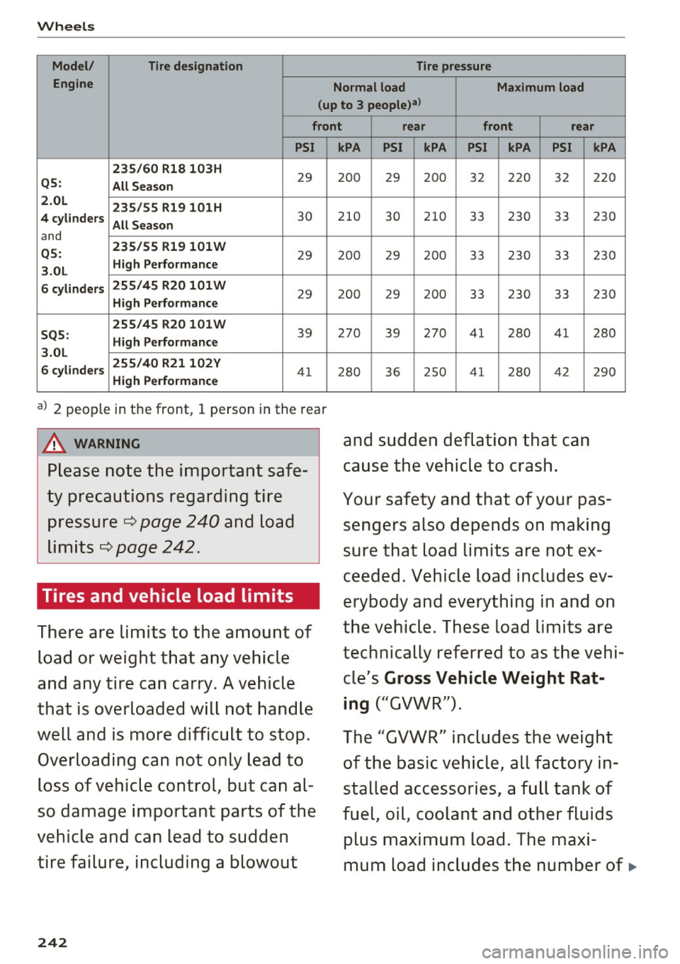
Make sure that the tire designa
tion on your tire matches the des
ignation on the tire pressure label
and the tire pressure table .
The following table lists recom
mended tire pressures in cold
tires according to the load and
the size of the tires installed .
241
Page 244 of 296
Wheels
Model/ Tire designation Tire pressure
Engine Normal load
Maximum load
(up to
3 people)a)
front rear front rear
PSI
235/60 Rl8 103H
29 Q5:
All Season
2.0L 235/55 Rl9 101H
4 cylinders
All Season
30
and
Q5: 235/55 Rl9
101 W 29 High Performance
3.0L
6 cylinders 255/45 R20 101W
29 High Performance
255/45R20101W
39 SQ5:
High Performance
3.0L
6 cylinders 255/40
R21102Y
41 High Performance
a) 2 people in the front, 1 perso n in the r ear
A WARNING
Please note the important safe
ty precautions regarding tire pressure ¢
page 240 and load
limits ¢
page 242.
Tires and vehicle load limits
There are limits to the amount of
load or weight that any vehicle
and any tire can carry . A vehicle
that is overloaded will not handle
well and is more difficult to stop.
Overloading can not only lead to
loss of vehicle control, but can al
so damage important parts of the
vehicle and can lead to sudden
tire failure, including a blowout
242
kPA PSI kPA PSI kPA PSI
200 29 2 00 32 220 32
210 30 210 33 230 33
200 29 200 33 230 33
2 00 29 2 00 3 3 230 33
270 39 270 41 280 41
2 80
36 2
50 41
28 0 42
and sudden deflation
that can
cause the vehicle to crash.
kPA
220
230
230
230
280
2 9 0
Your safety and that of your pas
sengers also depends on making
sure that load limits are not ex
ceeded. Vehicle load includes ev
erybody and everything in and on
the vehicle. These load limits are
technically referred to as the vehi
cle's
Gross Vehicle Weight Rat
ing
("GVWR") .
The "GVWR" includes the weight
of the basic vehicle, all factory in
stalled accessories , a full tank of
fuel, oil, coolant and other fluids
plus maximum load. The maxi
mum load includes the number of
11-
Page 250 of 296
Wheels
check your tires as soon as possible, and inflate
them to the proper pressure. Driving on a signifi
cantly under-inflated tire causes the tire to overheat and can lead to tire failure. Under-inflation
also reduces fuel efficiency and tire tread life,
and may affect the vehicle's handling and stop
ping ability.
Please note that the TPMS is not a substitute for
proper tire maintenance, and it is the driver's re
sponsibility to maintain correct tire pressure,
even if under-inflation has not reached the level
to trigger illumination of the TPMS low tire pres
sure telltale.
Your vehicle has also been equipped with a TPMS malfunction indicator to indicate when the sys
tem is not operating properly. The TPMS mal
function indicator is combined with the low tire pressure telltale. When the system detects a
malfunction, the telltale will flash for approxi
mately one minute and then remain continuously
illuminated. This sequence will continue upon
subsequent vehicle start-ups as long as the mal
function exists .
When the malfunction indicator is illuminated,
the system may not be able to detect or signal low tire pressure as intended . TPMS malfunctions
may occur for a variety of reasons, including the
installation of replacement or alternate tires or
wheels on the vehicle that prevent the TPMS from functioning properly . Always check the
TPMS malfunction telltale after replacing one or
more tires or wheels on your vehicle to ensure
that the replacement or alternate tires and
wheels allow the TPMS to continue to function
properly.
248
· If the Tire Pressure Monitoring System
indicator appears
Applies to: vehicles with Tire Pressure Monitoring System
The tire pressure indicator in the instrument
cluster informs you if the tire pressure is too low
or if there is a system malfunction.
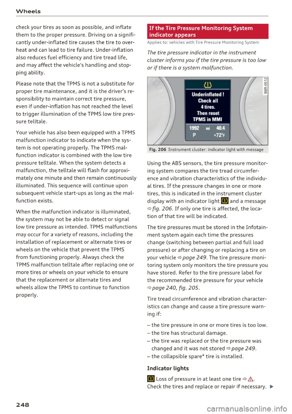
Fig. 206 Instrument cl uster: i ndic ator ligh t with message
Using the ABS sensors, the tire pressure monitor
ing system compares the tire tread circumfer
ence and vibration characteristics of the individu
al tires . If the pressure changes in one or more
tires , this is indicated in the instrument cluster
display with an indicator light
IE and a message
c>fig. 206. If only one tire is affected, the loca
tion of that tire will be indicated.
The tire pressures must be stored in the Infotain
ment system again each time the pressures
change (switching between partial and full load
pressure) or after changing or replacing a tire on
your vehicle
c> page 249. The tire pressure moni
toring system only monitors the tire pressure you have stored. Refer to the tire pressure label for
the recommended tire pressure for your vehicle
c> page 240, fig . 205.
Tire tread circumference and vibration character
istics can change and cause a tire pressure warn
ing if:
- the tire pressure in one or more tires is too low.
- the tire has structural damage.
- the tire was replaced or the tire pressure was
changed and it was not stored
c> page 249 .
-the collapsible spare* tire is installed.
Indicator lights
IE Loss of pressure in at least one tire c> &.
Check the tires and replace or repair if necessary . .,.
Page 264 of 296
Fuses and bulbs
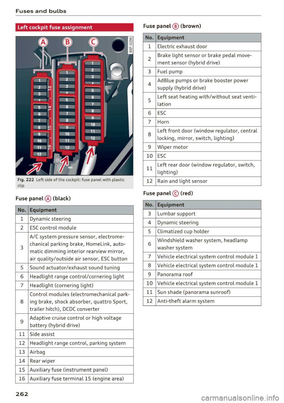
Left cockpit fuse assignment
Fig. 222 Left side of the cockp it: fuse panel with p lastic
clip
Fuse panel @ (black)
No . Equipment
1 Dynamic steering
2 ESC control module
A/C system pressure sensor, electrome-
3 chanical parking
brake, Homelink, auto-
matic dimming interior rearview mirror,
air quality/outside air sensor, ESC button
s Sound actuator/exhaust sound tuning
6 Headlight range control/corner ing light
7 Headlight (cornering light)
Control modules (electromechanical park-
8 ing brake, shock absorber, quattro Sport,
trailer hitch), DCDC converter
9
Adaptive cruise control or high voltage
battery (hybrid dr ive)
11 Side assist
12 Headlight range control, parking system
13 Airbag
14 Rear wiper
15 Auxiliary
fuse (instrument panel)
16 Auxiliary fuse te rm inal 15 (engine area)
262
Fuse panel ® (brown)
No. Equipment
1 Electric exhaust door
2 Brake
light sensor or brake pedal move-
ment sensor (hybrid drive)
3 Fuel pump
4 Ad
Blue pumps or brake booster power
supply (hybrid dr ive)
s
Left seat heating with/without seat venti-
lation
6 ESC
7 Horn
8
Left front doo r (window regulator, central
locking, mirror, switch, lighting)
9 Wiper motor
10 ESC
11 L
eft rear doo r (window regulator, switch,
li ght ing)
12 Rain and light sensor
Fuse panel
© (red)
No. Equipment
3 Lumbar support
4 Dynamic steering
5 Climatized cup holder
6 Windshie
ld washer system, headlamp
washer system
7 Vehicle electrical system control module 1
8 Vehicle electrical system control module 1
9 Panorama roof
10 Vehicle electrical system control module 1
11 Sun shade (panorama sunroof)
12 Anti-theft alarm system