technical data AUDI Q7 2010 Owner´s Manual
[x] Cancel search | Manufacturer: AUDI, Model Year: 2010, Model line: Q7, Model: AUDI Q7 2010Pages: 390, PDF Size: 93.04 MB
Page 165 of 390
______________________________________________ A_ u_ t_ o_ m_ a_ t_ ic_ t_r _a _n_ s_m _ i_s _s_ i_o _n _ ___.lJII
Select R only when the vehicle is at a full stop and the eng ine is
running at id le speed ~
& in "Driving the automatic transmission"
on
page 161 .
Before you move the selector lever to R, press both the button in the
hand le of the selector lever
and the brake pedal at the same t ime.
When the ignition is on, the backup lights illuminate when the
selector lever is moved into
R.
N -Neutral
The transmission is in neutral in this position . Shift to this position
for standing with the brakes applied~
page 163.
When the vehicle is stationary or at speeds below 3 mph (S km/h),
you must always apply the footbrake before and wh ile moving the
lever out of
N .
D -Normal position for driving forward
Position D is for normal city and highway driving. It ranges from zero
to top speed and all gears shift automatically, depending on engine
load, driving speed and automatically selected shift programs.
When the vehicle is stationary or at speeds below 3 mph (S km/h),
you must always apply the foot brake before and while moving the
lever to
D out of N.
In certa in circumstances it may be advantageous to temporarily
switch to the manual shift program to manua lly select gear ratios to
match specific driving conditions~
page 165.
S -Sport position
Select this position for sportier performance. In this position, the
transmission will not upshift as soon, allowing the vehicle to use the
increased power available at higher engine speeds to achieve livelier
acceleration.
When the vehicle is stat ionary or at speeds be low 3 mph (5 km/h),
you must always apply the foot brake before and while moving the
lever to
S out of N.
Con tro ls a nd e quip
m en t Vehicle
OP-eration
& WARNING
Read and follow all WARNINGS~ & in "Driving the automatic
transmission" on
page 161.
0 Note
Coasting downh ill with the transmission in N and the engine not
running will result in damage to the automatic transmission and
possibly the cata lytic converter. •
Automatic Shift lock (ASL)
The Automatic Shi~ Lock safeguards you against acci
dentally shifting into a forward or the reverse gear and
causing the vehicle to move unintentionally.
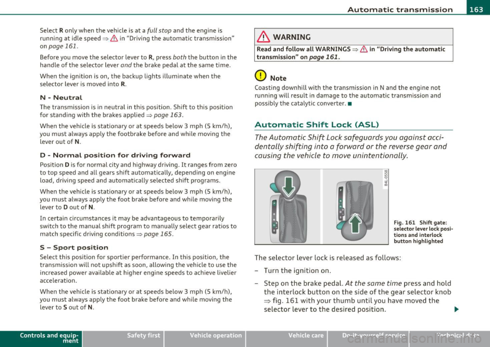
Fig. 161 Shift gate:
selector lever lock posi
tions and interlock
button highlighted
The selector lever lock is released as follows:
- Turn the ignition on.
- Step on the brake pedal.
At the same time press and hold
the interlock button on the side of the gear selector knob
~ fig. 161 with your thumb until you have moved the
selector lever to the desired position . _..
Vehicle care Do-it-yourselt service iTechnical data
Page 167 of 390
______________________________________________ A_ u_ t_ o_ m_ a_ t_ ic_ t_r _a _n_ s_m _ i_s _s_ i_o _n _ ___.1111
driver presses the brake pedal on a downhill gradient . This makes use
of the braking effect of the engine without the need to shift down
manually .•
Manual shift program
Using the manual shift program you can manually select
gears.
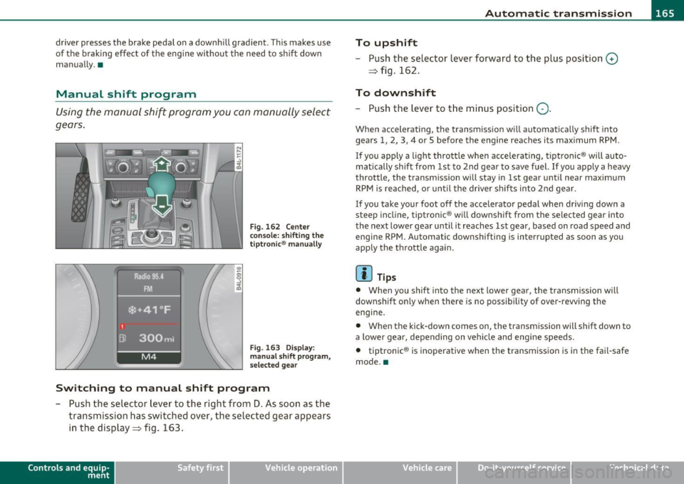
Fig. 162 Center
console : shifting the
tiptronic ® manually
Fig . 163 Display:
manual shift program,
selec ted gear
Switching to manual shift program
-Push the selector lever to the right from D. As soon as the
transmission has switched over, the selected gear appears
in the display => fig . 163.
Con tro ls a nd e quip
m en t Vehicle
OP-eration
To upshift
-Push the selector lever forward to the plus position 0
=> fig . 162.
To downshift
- Push the lever to the minus position Q.
When accelerating, the transm ission w ill automatically shift into
gears 1, 2, 3, 4 or 5 before the engine reaches its maximum RPM .
I f you apply a light throttle when accelerating, tiptronic ® will auto
matically shift from 1st to 2nd gea r to save fuel. If you apply a heavy
throttle, the transmission will stay in 1st gear until near maximum
RPM is reached, or until the driver shifts into 2nd gear.
If you take your foot off the accelerator pedal when driv ing down a
st eep incline, tiptronic ® will downshift from the selected gear into
the next lower gear until it reaches 1st gear, based on road speed and
e ngine RPM. Automatic downsh ifting is interrupted as soon as you
apply the throttle again.
[ i ] Tips
• When you shift into the next lower gear, the transmission will
downshift on ly when there is no possibility of over-rewing the
engine.
• When the kick -down comes on, the transmission will shift down to
a lower gear, depending on vehicle and engine speeds.
• tiptronic ® is inoperative when the transmission is in the fail-safe
mode. •
Vehicle care Do-it-yourselt service iTechnical data
Page 169 of 390

______________________________________________ A_ u_ t_ o _ m_ a_ t_ ic_ t_r_a _ n_ s_m_ i_ s _s_ i_ o _ n __ ffllll
- Now press the inter lock an d mov e the sel ector lever to the
N pos ition.
Th e se lecto r leve r ca n only be moved from the P position if the ign i
tion key is in the lock and the ign it ion is turned on. If the vehicle has
t o be pushed or towed if the power supp ly fai ls (e .g. battery is
discharged), the selector lever must be moved to the
N position using
t he emergency lock ing devi ce. •
Controls and equip
ment Safety first
Vehicle care Technical data
Page 171 of 390
______________________________________________ _:P_ a=.:... r:.:k ;.:in :..:.;;; g!.....:: s.,?.y .=s :..:t :.:e :.: m...:..:.._..J_
Parking system advanced
App lies to veh icles: wit h pa rk ing syste m advanced
Introduction
0, g ~ ..!J
~================- i
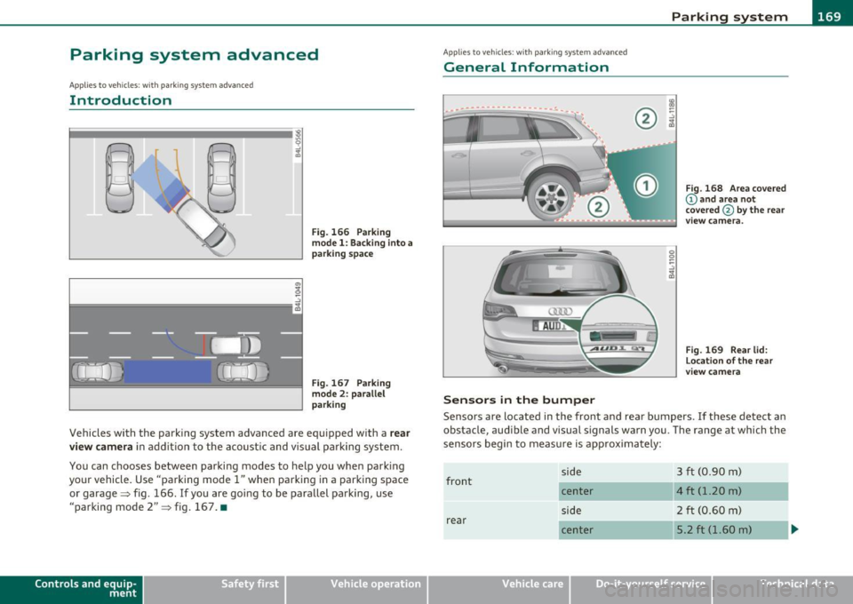
Fig. 166 Parking
model: Backing into a
parking space
Fig. 167 Parking
mode 2: parallel
parking
Vehicles with the parking system advanced are equipped with a rear
view camera
in addition to the acoustic and visual parking system.
You can chooses between parking modes to help you when parking
your vehicle. Use "parking mode
1" when parking in a parking space
or garage~ fig. 166 .
If you are going to be parallel parking, use
"parking mode
2" ~ fig. 167. •
Contro ls a nd e quip
m en t Vehicle
OP-eration
Applies to vehicles : w ith par kin g system advanced
General Information
Sensors in the bumper
Fig. 168 Area covered
@ and area not
covered @
by the rear
v iew camera.
Fig. 169 Rear lid:
Location of the rear
view camera
Sensors are located in the front and rear bumpers . If these detect an
obstacle, audible and visual signals warn you. The range at which the
sensors begin to measure is approximately:
front
rear side
center
side
center
Vehicle care
3 ft (0
.90 m)
4 ft (1.20 m)
2 ft (0.60 m)
5.2 ft (1.60 m)
Do-it-yourselt service iTechnical data
Page 173 of 390

Parking system -
----------------=-------'
Applies to veh icles : w ith par king system advanced
Switching on and off
Th e rear view camera switches on automatically together
with the acoustic and visual park assist when you put the
vehicle in reverse.
Switching on
F ig. 170 Cente r
c on sole: Pa rki ng
sys tem swi tch
Fig . 171 MMI display:
v is ual d istance disp la y
- Switch the MMI on and select reverse gear.
- Switch on the Adaptive Air Suspension * comfort or auto-
matic mode .
Contro ls a nd e quip
m en t Vehicle
OP-eration
-To use the front parking system , press the switch P11.1A in the
center console ~ fig . 170 . A short confirmat ion tone
sou nds an d the indicator light in the sw itch lights up.
Switching between the rear view camera and
visual display
- Press the Graphic control button~ page 172, fig. 172 ®
to see the visual dis pla y.
- P ress the
Rear view control button to see the rear view
camera image~ fig . 171.
Switching off
Drive faster than 6 mph ( 10 km/h), or
- press th e swi tch
P111 A or
- switch off the ignition .
Segments in the visual display
The red segments i n front of and behind the vehicle=> fig . 171 help
you to determine the distan ce between you and an obstacle . As your
vehicle comes closer to the obstacle, the segm ents move closer to the
veh icle . The co llision area has been reached when t he next to last
segmen t is displayed . Do not cont inue dr iv ing farthe r=>
& in
"Ge neral Information " on
page 169!
& WARNING
• The MMI display cannot show , or cannot adequately show ,
c ertain objects (such a s small posts or grating ), reces ses in the
ground and protruding parts on another car.
• Onl y use the rear view camera to a ssist you if it show s a good ,
clear picture. For e xample, the image may be affected by the sun
shining into the lens , dirt on the len s or if there is a defect. .,_
Vehicle care Do-it-yourselt service iTechnical data
Page 175 of 390
Parking system -
----------------=-------'
& WARNING (continued )
you should not use the help lines to help with parking, which
poses danger of an accident!
0 Note
In the MMI display , the direction of travel of the vehicle rear is repre
sen te d dependin g on the s teering wheel ang le . The vehicle fron t
swings out more than the vehicle rear. Maintain plenty of distance so
that your outside mirror or a corner of your vehicle does not collide
with any obstacles. This can damage to your vehicle. •
Applies to ve hicles : w ith pa rk ing system advanced
Parallel Parking
Use parking mode 2 to help you parallel pork along the
side of a street.
Con tro ls a nd e quip
m en t
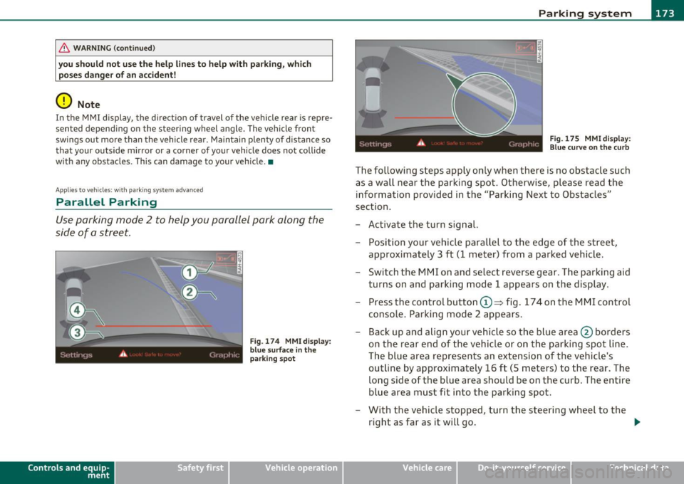
Fig . 174 MMI display:
blue surface in the
parking spot
Vehicle OP-eration
Fig. 175 MMI display:
Blue curve on the curb
The following steps apply only when there is no obstacle such
as a wall near the parking spot. Otherwise, please read the information provided in the "Parking Next to Obstacles"
section.
- Activate the turn signal.
- Position your vehicle parallel to the edge of the street,
approximately 3 ft (1 meter) from a parked vehicle.
- Switch the MMI on and select reverse gear . The parking aid
turns on and parking mode 1 appears on the display .
Press the control button©~ fig. 174 on the MMI control
console. Parking mode 2 appears.
- Back up and align your vehicle so the blue area @ borders
on the rear end of the vehicle or on the parking spot line.
The blue area represents an extension of the vehicle's
outline by approximately 16 ft (5 meters) to the rear. The
long side of the blue area should be on the curb. The entire
blue area must fit into the parking spot.
- With the vehicle stopped, turn the steering wheel to the
right as far as it will go. _.,
Vehicle care Do-it-yourselt service iTechnical data
Page 177 of 390

Parking system -
--------------=--=---
[I) Tips
• The warn ing tones can also be adjusted d irectly by the v isua l
display* or the picture from the rear view camera* . Simply press t he
S ettings * control butto n.
• Changed settings are activated when park ing system is switched
on again.
• T he settings are automatically stored and assigned to the remote
control key. •
Applies to veh icles: w ith rear park assist/park ing system advanced and t ra iler h itch
Trailer hitch
For vehicles with a factory installed trailer hitch, or a trailer hitch
ins talled a cco rding to factory specifica tions, the p arking sys tem rear
sensors do not come on whenever you shift into reverse gear or when
you p ress the
P,.,1~ swit ch*. If yo u install a hitch yourse lf, this f unction
may not work. In genera l the follow limitations may come up:
Rear park assist*
There is no warning for distances to the rear.
Parking system advanced *
There is no warning for d istances to the rear. The front sensors
remain act ivated. The v isua l display sw itches to the trailer tow ing
mode. The p icture from the rear v iew camera will not show the orien
tat ion li nes nor the bl ue surfaces. •
Applies to veh icles: with rear park ass ist/park ing sys tem advanced
Error messages
There is an erro r in the system if the LED on the Pwi switc h* is blink ing
and you he ar a continuous alarm for a few se con ds afte r swi tching on
Controls and equip
ment Safety first
the parking system or when the parking system
is a lready activated.
Have your au thor ize d Aud i deale r co rrec t th e error.
[I) Tips
If the er ror is not corrected befo re yo u switch off the ignition, when
you sw itch on the parking system again, the LED in the
P'#A sw itch * will
blink. •
Vehicle care Technical data
Page 179 of 390
____________________________________________ A_ d_a_ p ,_ t_iv _ e_ A _ i_ r _ S_ u_s_, p __ e_n _ s_ i _o_ n __ ffllll
A pp lies to ve hicles : with A dap tive Air Su spen sion
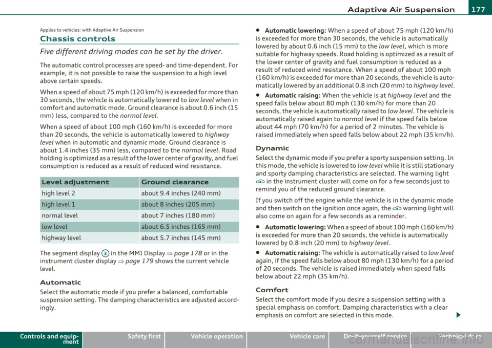
Chassis controls
Five different driving modes can be set by the driver.
The automatic control processes are speed- and time-dependent. For
example, it is not possible to raise the suspension to a high level
above certain speeds.
When a speed of about 75 mph (120 km/h) is exceeded for more than
30 seconds, the vehicle is automatically lowered to
low level when in
comfort and automatic mode. Ground clearance is about 0.6 inch (15
mm) less, compared to the
normal level.
When a speed of about 100 mph (160 km/h) is exceeded for more
than 20 seconds, the vehicle is automatically lowered to
highway
level
when in automatic and dynamic mode . Ground clearance is
about 1.4 inches (35 mm) less, compared to the
normal level. Road
holding is optimized as a resu lt of the lower center of gravity, and fuel
consumption is reduced as a result of reduced wind resistance .
Level adjustment
high level 2
normal level
highway level
Ground clearance
about 9.4 inches (240 mm)
about 8 inches (205 mm)
about 7 inches (180 mm)
about 6.5 inches (165 mm)
about 5. 7 inches (145 mm)
The segment display @ in the MMI Display =>
page 178 or in the
instrument cluste r display =>
page 179 shows the current vehicle
level.
Automatic
Select the automatic mode if you prefer a balanced, comfortable
suspension setting. The damp ing characteristics are adjusted accord
ing ly .
Controls and equip
ment Safety first •
Automatic lowering: When a speed of about 75 mph (120 km/h)
is exceeded for more than 30 seconds, the veh icle is automatically
lowered by about 0 .6 inch (15 mm) to the
low level, which is more
suitable for highway speeds. Road holding is optimized as a result of
the lower center of gravity and fuel consumpt ion is reduced as a
result of reduced wind resistance . When a speed of about 100 mph
(160 km/h) is exceeded fo r more than 20 seconds, the vehicle is auto
matically lowered by an additional 0.8 inch (20 mm) to
highway level.
• Automatic raising: When the vehicle is at highway level and the
speed falls below about 80 mph (130 km/h) for more than 20
seconds, the vehicle is automat ically raised to
low level. The vehicle is
automatically raised again to
normal level if the speed falls below
about 44 mph (70 km/h) for a period of 2 minutes. The vehicle is
raised immediately when speed falls below about 22 mph (35 km/h).
Dynamic
Select the dynamic mode if you prefer a sporty suspension setting . In
this mode, the vehi cle is lowe red to
low level wh ile it is still stationary
and sporty damp ing characteristics a re selected . The warning light
c.:> in the instrument cluster wi ll come on for a few seconds just to
remind you of the reduced ground clearance.
If you switch off the engine whi le the vehicle is in the dynamic mode
and then switch on the ignition once again, the
c.:> warning light will
also come on again for a few seconds as a reminder .
• Automatic lowering : When a speed of about 100 mph (160 km/h)
is exceeded fo r more than 20 seconds, the vehicle is automatically
lowered by 0.8 inch (20 mm) to
highway level.
• Automatic raising: The vehicle is automatically raised to low level
again, if the speed falls below about 80 mph (1 30 km/h) for a per iod
of 20 seconds. The vehicle is raised immediately when speed falls
below about 22 mph (35 km/h).
Comfort
Select the comfort mode if you desire a suspension setting with a
special emphasis on comfort. Damping characteristics with a clear
emphasis on comfort are selected in this mode.
~
Vehicle care Technical data
Page 181 of 390
____________________________________________ A_ d_a ..... p,__ t_iv _ e_ A_ i_r _ S_ u_s__, p_ e_n _ s_ i_ o _ n _ __.ffl'I
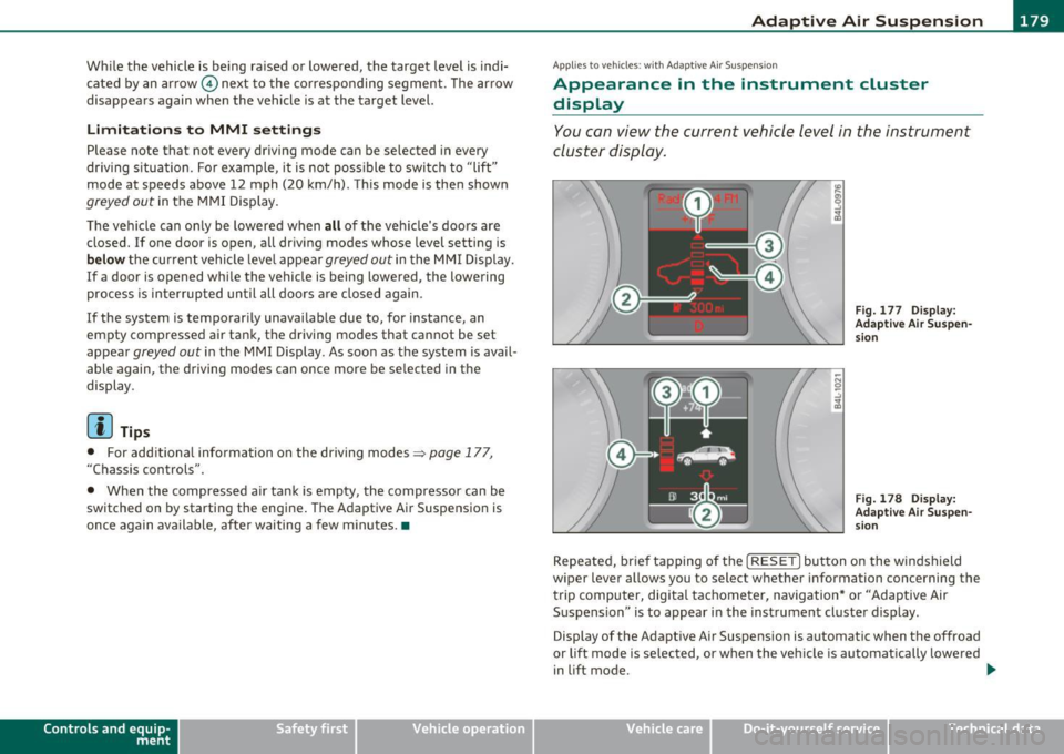
While the vehicle is being raised or lowered, the target level is indi
cated by an arrow © next to the corresponding segment. The arrow
disappears again when the vehicle is at the target level.
Limitations to MMI settings
Please note that not every driving mode can be selected in every
dr iving s ituation . For example , it is not poss ible to switch to "lift"
mode at speeds above 12 mph (20 km/h) . This mode is then shown
greyed out in the MMI Display .
The vehicle can on ly be lowered when
all of the veh icle's doors are
closed.
If one doo r is open, all driving modes whose level setting is
below the current vehicle level appear greyed out in the MMI Display.
If a door is opened whi le the vehicle is being lowered , the lowering
process is interrupted until all doo rs are closed again.
I f the system is temporarily unavailable due to, for instance, an
empty compressed air tank, the driving modes that cannot be set
appear
greyed out in the MMI Display . As soon as the system is avail
able aga in, the driv ing modes can once more be selected in the
display .
(I] Tips
• For additional information on the driving modes=> page 177,
"Chassis controls".
• When the compressed air tank is empty , the compressor can be
switched on by starting the engine. The Adaptive Air Suspension is
once again available, after waiting a few minutes. •
Contro ls a nd e quip
m en t Vehicle
OP-eration
Applies to vehicles : w ith Adapt ive A ir Sus pens ion
Appearance in the instrument cluster
display
You can view the current vehicle level in the instrument
cluster display.
Fig. 177 Display:
Adaptive Air Suspen sion
Fig. 178 Display:
Adaptive Air Suspen
s ion
Repeated, br ief tapping of the [ RESET] button on the windshield
wiper lever allows you to selec t whether information concerning the
trip computer, digita l tachometer, navigation* or "Adaptive Air
Suspension " is to appear in the instrument cluster display .
Display of the Adaptive Air Suspension is automatic when the offroad
or lift mode is se lected, or when the vehicle is automat ically lowered
i n lift mode.
~
Vehicle care Do-it-yourselt service iTechnical data
Page 183 of 390

____________________________________________ A_ d_a_ p ,_ t_iv _ e_ A _ i_ r _ S_ u_s_, p __ e_n _ s_ i _o_ n __ _
ically raised to high level 1 again when the traveling speed falls below
approximately 25 mph (40 km/h) .
Restrictions when operating with a trailer
When operating with a trailer, the lift mode can only be selected up
to about 12 mph (20 km/h). Lift mode is automatically canceled
agai n when a speed of about 25 mph (40 km/h) is exceeded.
If the vehicle is in automatic , comfort, offroad or lift mode before the
trailer towing mode is activated, the dynamic mode cannot be acti
vated .
If the vehicle is in dynam ic mode before towing operation is acti
vated, it can be driven in this mode. If the suspension is switched
from th is mode to another mode, dynamic mode cannot be re
selected.
[I) Tips
• For vehicles with a factory installed towing hitch or a trai ler hitch
that was installed later according to factory specifications, the
system recognizes "Trailer towing mode" and activates this specia l
mode automat ically , as soon as the electr ical connection on the
trailer socket is connected. The mode ceases automatically when the
electrical connection to the trailer socket is disconnected.
• If the trai ler towing mode has been activated, the vehicle will not
drop to the low o r highway level. •
Controls and equip
ment Safety first
A
pp lies to vehicles : w ith Adapt ive Air Sus pens ion
Cargo mode
The rear of the vehicle can be lowered to make it easier to
load .
Fig. 179 Luggage
compartment detail:
Cargo mode switch
Activating cargo mode in the MMI
-Select: Function button [CARI> function button [SETUP)
> Lower for loading.
Using switch for activating cargo mode
- Close all vehicle doors.
- Open the trunk lid.
- Press the lower part of the switch ®~ fig. 179. The rear
of the vehicle is lowered.
- Press the upper part of the switch
(D. The rear of the
veh icle is raised again.
In cargo mode, the rear axle is lowered by 2.2 inches (55 mm),
compa red to the normal level.
While the vehicle is in cargo mode, the segments do not appear as
filled in the segment d isplay. .,,
Vehicle care Technical data