air suspension AUDI Q7 2012 Owner´s Manual
[x] Cancel search | Manufacturer: AUDI, Model Year: 2012, Model line: Q7, Model: AUDI Q7 2012Pages: 342, PDF Size: 86.42 MB
Page 5 of 342
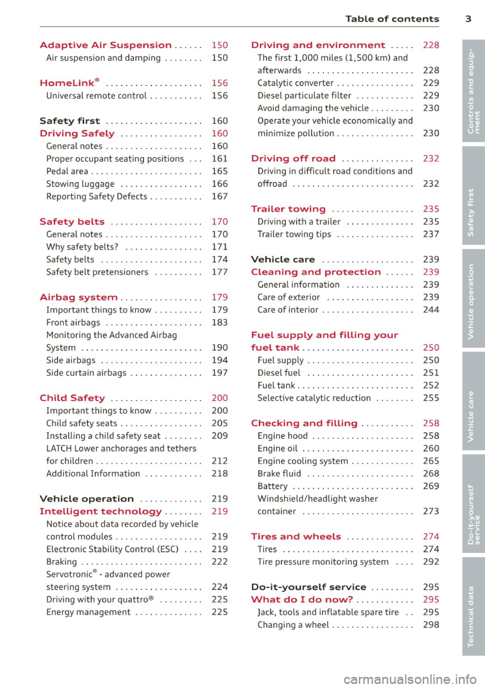
Adaptive Air Suspension .. .. . .
Air suspension and damping 150
150
Homelink ® . . . . . . . . . . . . . . . . . . . . 156
Universal remote control . . . . . . . . . . . 156
Safet y fir st . . . . . . . . . . . . . . . . . . . . 160
Driving Safely . . . . . . . . . . . . . . . . . 160
Gene ral notes . . . . . . . . . . . . . . . . . . . . 160
Proper occupant seating posit ions . . . 161
Ped al area . . . . . . . . . . . . . . . . . . . . . . . 165
Stowing luggage . . . . . . . . . . . . . . . . . 166
Report ing Safety Defects . . . . . . . . . . . 167
Safety belts . . . . . . . . . . . . . . . . . . . 170
General notes . . . . . . . . . . . . . . . . . . . . 170
Why safety belts? . . . . . . . . . . . . . . . . 171
Safety belts . . . . . . . . . . . . . . . . . . . . . 17 4
Safety bel t pretens ioners . . . . . . . . . . 177
Airbag system .......... ... ... .
Important things to know .. .. .. .. . .
Fr ont airbags ............ .... .. . .
M on itoring the A dvanced Airbag
System .... .. ... .. ..... ... .. .. . .
Side airbags . ... ...... ... .. .. .. . .
Side curtain airbags .... ... .. .. .. . .
Child Safety .. .. .... ... .. .. .. . .
Important th ings to know . ... .. .. . .
Ch ild safety seats ......... .... .. . .
Instal ling a child safety seat .. .. .. . .
LATC H Lower ancho rages and tethers
for chi ldren .... .. .. ...... .. .. .. . .
Addit ional Information
Vehicle operation ..... .. .. .. . .
Intelligent technology .. .. . .. .
179
179
183
190
194
197
200
200
205
209
212
218
219
219
Not ice about data recorded by vehi cle
con trol mod u Les . . . . . . . . . . . . . . . . . . 2 19
E lect ronic S tabili ty Control ( ES C) . . . . 219
Braking . . . . . . . . . . . . . . . . . . . . . . . . . 222
Servotronic ® -advanced power
steering system . . . . . . . . . . . . . . . . . . 224
Driving w ith your quattro ® . . . . . . . . . 225
Energy management . . . . . . . . . . . . . . 225
Table of contents 3
Driving and environment . . . . .
228
The first 1,000 miles (1,SOO km) and
afterwa rds . . . . . . . . . . . . . . . . . . . . . . 228
Catalytic co nverter . . . . . . . . . . . . . . . . 229
Diesel particulate filter . . . . . . . . . . . . 229
Avoid damaging the vehicle . . . . . . . . . 230
Operate your vehicle eco nomically and
min imize poll ution . . . . . . . . . . . . . . . . 230
Driving off road . . . . . . . . . . . . . . . 232
Driving in d ifficult road conditions and
offroad . . . . . . . . . . . . . . . . . . . . . . . . . 232
Trailer towing . . . . . . . . . . . . . . . . . 235
D riving with a trailer . . . . . . . . . . . . . . 235
T rai le r tow ing tips . . . . . . . . . . . . . . . . 237
Vehicle care . . . . . . . . . . . . . . . . . . . 239
Cleaning and protection . . . . . . 239
General information . . . . . . . . . . . . . . 239
Care of ex terior . ... .. .. .. .... ... .
Care of inte rior ... .. . .. .. ..... ... .
Fuel supply and filling your
fuel tank ... .... .. . .. .. ..... ... .
Fuel supply ...... .. . .. .. ..... ... .
Diesel f uel .. .. .. .. .. ... ..... ... .
Fuel tank .. .. .. .. .... ........... .
Se lective cata lytic reduction ..... .. .
Checking and filling .......... .
Engine hood ... .. ............... .
E n gine oi l ... .... ... .. .... ...... .
Engine cooling system .. .. ... ..... .
B rake fluid ....... ...... ........ .
B attery ... .. .. .. .. . ............ .
Windsh ie ld/headl ight washer
conta iner . .. .. .. .. ............. . 239
244
25
0
250
251
252
255
258
258
260
265
268
2 69
2 73
Tires and wheels . . . . . . . . . . . . . . 274
T ires . . . . . . . . . . . . . . . . . . . . . . . . . . . 274
T ire pressure monitoring system 292
Do -it -yourself service . . . . . . . . . 295
What do I do now? . . . . . . . . . . . . 295
Jack , tools and inflatab le spare tire . . 295
Changing a wheel . . . . . . . . . . . . . . . . . 298
•
•
Page 16 of 342
14 Instruments and warning/indicator lights
Warning/indicator lights
Overview
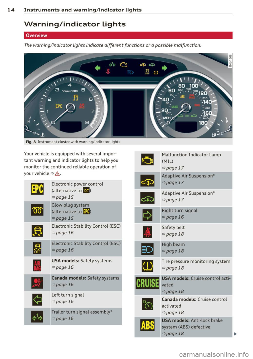
The warning/indicator lights indicate different functions or a possible malfunction.
Fig . 8 Instrument duster w ith warning/indicator ligh ts
Your veh icle is equipped with several impor·
a
Malfunction Indicator Lamp
tant warning and indicator lights to help you (MIL)
monitor the continued reliable operation of
<=:>page 17
your veh icle c:> _& .
•
Adaptive Air Suspension*
rm
Electron ic power control <=:>page 17
(alternative to l,;I) -
•
Adaptive Air Suspension*
<=:>page 15
<=:>page 17
II
Glow plug system ~
(alternative to~
rl
Right turn signal
<=:>page 15 <=:>page
16
•
Electron ic Stability Control (ESC)
Safety belt
<=:>page 16
<=:>page 18
I
Electronic Stability Control (ESC)
•
High beam
<=:>page 16
¢page 18
USA models: Safety systems
[g
Tire pressure monitoring system
<=:>page 16
<=:>page 18
Canada models : Safety systems
gm
USA models: Cruise control acti·
<=:>page 16 vated
<=:>page 18 j
Left turn signal
E
Canada models: Cruise control <=:>page 16
•
activated
•
Trailer turn signal assembly* c:>pafe 18
<=:>page 16
~
USA models: Anti-lock brake
system (ABS) defective
¢page 18
Page 19 of 342
Instruments and warning/indicator lights 17
o Malfunction Indicator Lamp (MIL)
The Malfunction Indicator Lamp (M IL) is part
of the On-Board Diagnostic (OBD II) system.
The symbol
f• lights up when the ignition is
turned on and will turn off after the engine
has started and has sett led at a constant idle
speed. Th is ind icates that the MIL is working
properly.
The warning light illuminates when there is a
malfunction in the engine electronic system .
Contact your author ized Audi dealer and have
the ma lfunction corrected.
An improperly closed fuel filler cap may also
cause the MIL light to illuminate (only vehi
cles with gasoline engine)
c:> page 253.
For more informat ion c:> page 2 7.
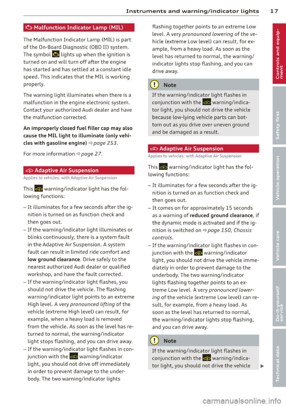
0 Adaptive Air Suspension
Applies to vehicles: with Adaptive Air Suspension
This II warning/indicator light has the fol
l owing functions:
- It illuminates for a few seconds after the ig
nition is turned on as function check and
then goes out .
- If the warning/ind icator light illuminates or
blinks continuously, there is a system fau lt
in the Adaptive A ir Suspension . A system
fault can result in limited ride comfort and
low ground clearance . Drive safely to the
nearest authorized Aud i dealer or qualified
workshop, and have the fault corrected .
- If the warning/ind icator light flashes, you
should not drive the vehicle. The flash ing
warning/ind icator light po ints to an extreme
High level. A very
pronounced lifting of the
vehicle (extreme High level) can resu lt, fo r
example, when a heavy load is removed
from the vehicle. As soon as the leve l has re
turned to normal, the warning/indicator
light stops flashing, and you can drive away.
- If the warning/ind icator light flashes in con
junction with the
II warning/indicator
light, you sho uld not drive off immediately
i n order to prevent damage to the under
body. The two warning/ind icator lights flashing together points to an extreme Low
level. A very
pronounced lowering of the ve
hicle (extreme Low leve l) can result, for ex
ample, from a heavy load. As soon as the
level has retu rned to normal, the warning/
ind icator lights stop flashing, and you can
drive away.
(D Note
If the warning/indicator light flashes in
conjunction with the
II warni ng/indica
tor light, you should not dr ive the veh icle
because low-lying vehicle parts can bot
tom out as you drive over uneven ground
and be damaged as a result.
~ Adaptive Air Suspension
Applies to vehicles: with Adaptive Air Suspension
This II warning/ indicator light has the fol
lowing functions:
- It illuminates for a few seconds after the ig
nition is turned on as function check and
then goes out.
- It comes on for approximately 15 seconds
as a warning of
reduced ground clearance , if
the dynamic mode is activated and if the ig
nition is switched on
r:!;> page 150, Chassis
controls.
- If the warning/indicator light flashes in con
junction with the
II warning/indicator
light, you should not drive the vehicle imme
diately in order to prevent damage to the
underbody. The two warn ing/ indicator
lights flashing together points to an ex
treme Low level. A very
pronounced lower
ing
of the vehicle (extreme Low level) can re
sult, for example, from a heavy load. As
soon as the level has returned to normal,
the warning/indicator lights stop flashing,
and you can drive away.
(D Note
If the warning/indicator light flashes in
conjunction with the
II warning/indica
tor light, you should not drive the vehicle
Page 23 of 342
Driver information
display
Introduction
General notes
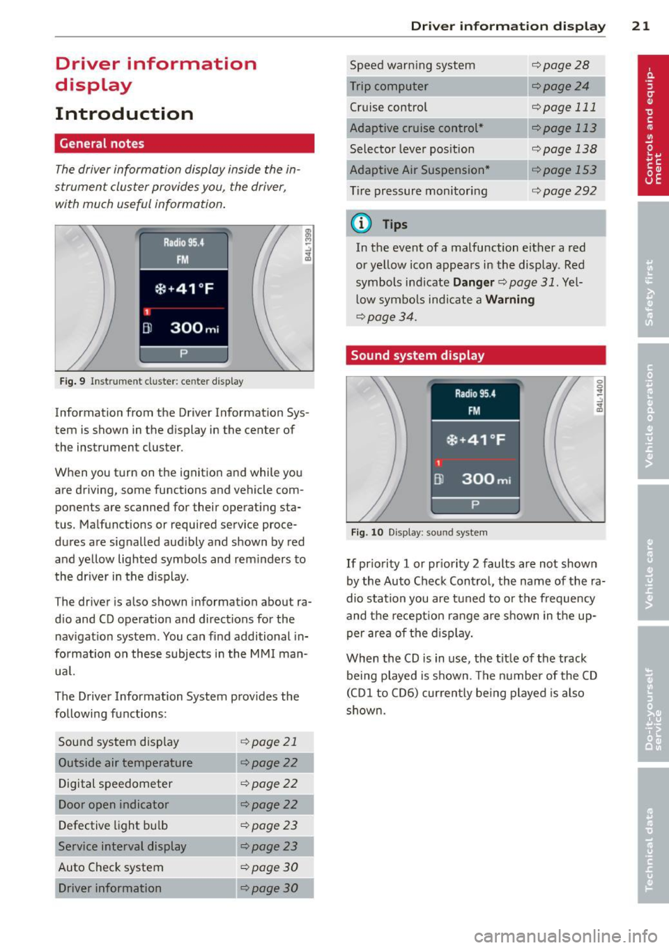
The driver informa tion display inside the in
strument cluster provides you, the driver,
with much useful information.
Fig. 9 Instr ument cluster: ce nter display
Information from the Driver Information Sys
tem is shown in the display in the center of
the instrument cluster.
When you turn on the ignition and while you
are driving, some functions and vehicle com
ponents are scanned for their operating sta
tus. Malfunctions or required service proce
dures are signalled aud ibly and shown by red
and yellow lighted symbols and rem inders to
the dr iver in the display.
The driver is also shown information about ra
d io and CD operation and directions for the
nav igation system . You can f ind additional in
formation on these subjects in the MMI man
ua l.
The Driver Information System prov ides the
following functions:
Sound system disp lay ¢
page 21
Outside air temperature ¢page22
Digital speedometer ¢page
22
Door open indicator ¢page22
Defective light b ulb ¢poge23
Service interval display ¢page23
Auto Check system ¢
page 30
Driver information ¢page30
Dri
ver inform ation di spl ay 21
Speed warn ing system
Cruise control
Adaptive cruise control *
Selector lever pos ition
Adaptive Air Suspension *
T ire pressure monitori ng
(D Tips
¢page28
--·--¢page24
¢page 111
--..--
¢page 113
¢page 138
¢page292
In the event of a malfunction either a red
or ye llow icon appears in the display . Red
symbols indicate
Dang er ¢ page 31. Yel
l ow symbo ls indicate a
Warning
¢ page 34.
Sound system display
Fig. 10 Display: sound syste m
If priority 1 or pr iority 2 faults are not shown
by the Auto Check Control, the name of the ra
dio station you are tuned to or t he frequency
and the recept ion range are shown in the up
per area of the d isplay.
When the CD is in use, the tit le of the track
being played is shown. The number of the CD
(CDI to CD6) cur rently be ing played is also
s h own.
Page 148 of 342
146 Parking system
Switching on and off
Applies to vehicles: with Audi parking system plus w ith
rea rview camera
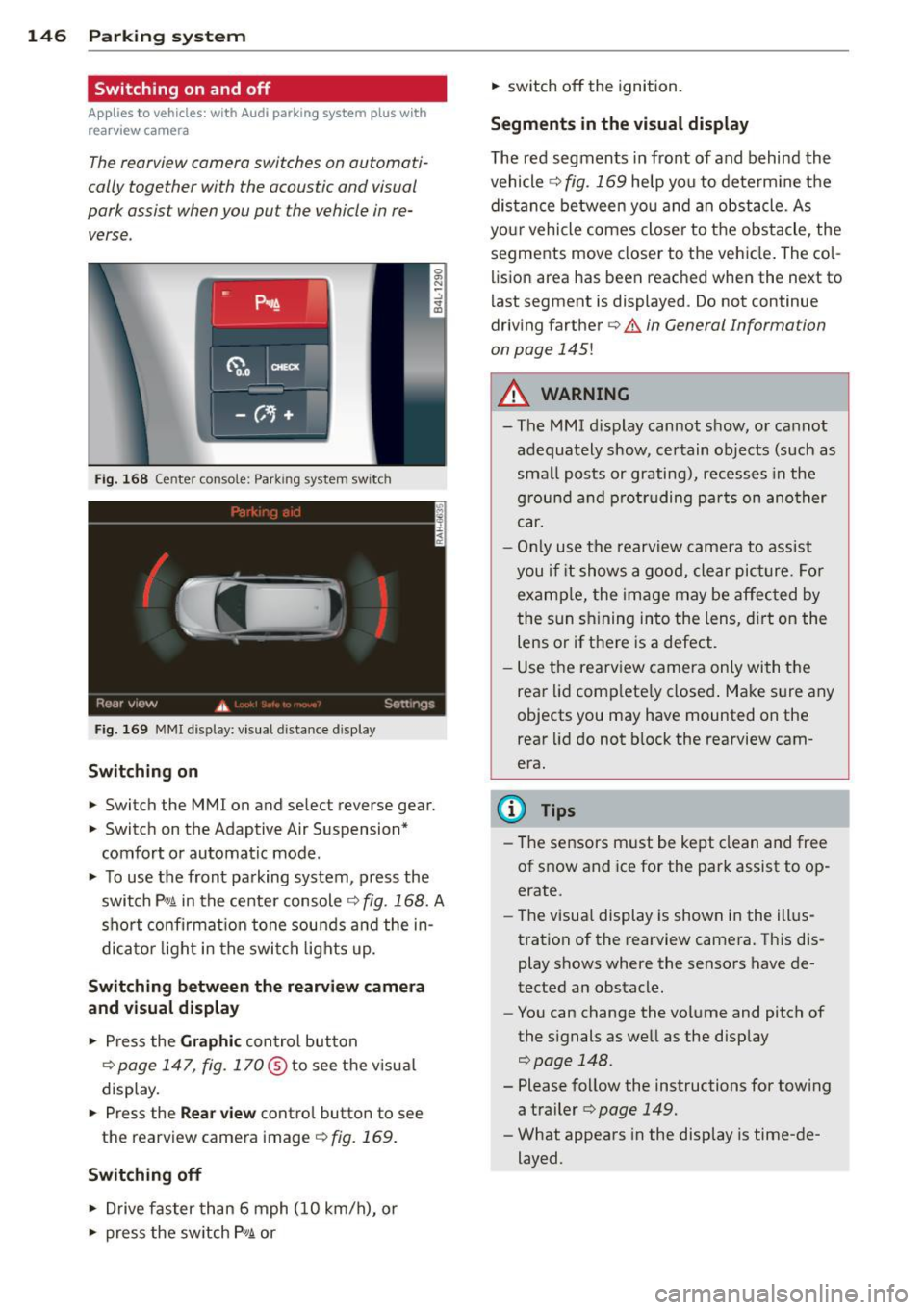
The reorview camera switches on automati
cally together with the acoustic and visual
pork assist when you put the vehicle in re verse .
Fig. 168 Ce nter console: Park ing system switc h
Fig. 169 MMI display: visual d istance d isplay
Switching on
> Switch the MMI on and se lect reverse gear.
> Switc h on the Adaptive Air Suspension*
comfort or automatic mode.
> To use the front pa rking system , press the
switch P"1t in the center console
c:> fig. 168. A
short confirmat ion tone sou nds a nd the in
di ca to r li ght in the swi tch lights up.
Switching betwe en the r earview camera
and visual display
> Press the Graphi c control button
¢
page 147, fig. 170@to see the v isua l
display.
> Press the Rea r view contro l button to see
the rearview camera image
<=:> fig. 169.
Switching off
> Drive faster than 6 mph (10 km/h), or
> press the sw itch P 1t or
> switch off the ignition.
Segm ents in the visual display
The red segments in fro nt of and behind the
vehicle
<=:> fig. 169 help you to determ ine t he
distan ce between yo u and an obstacle. As
your vehicle comes close r to the obstacle, the
segments move closer to the vehicle . The co l
lision area has been reached when the next to
l ast segment is displayed . Do not continue
driving farther ¢
& in General Information
on page
145!
A WARNING
-
- The MMI d isplay cannot show, or ca nnot
adequately show, certain objects (such as
sma ll posts or grating), recesses in the
g rou nd a nd p rot ruding pa rts on ano ther
car.
- Onl y use t he rearview camera to ass ist
you i f it shows a good, clear pic ture. For
examp le, the image may be affec ted by
the sun s hining into the lens, d irt on the
lens or if there is a defect.
- Use the rearv iew came ra only wi th the
rear lid comp lete ly closed . Make s ure any
objects you may have mounted on the
rear lid do not b lock the rearview cam
era.
(D Tips
- The sensors m ust be kept clean and free
of snow and ice for the park assist to op
erate.
- The visua l display is shown in the ill us
tration of the rearview camera. Th is dis
play shows where the sensors have de
tected an obstacle.
- You can change the volume and pitch of
the s ignals as we ll as the disp lay
c:> page 148.
- Please follow the instructions for tow ing
a trailer
c:> page 149.
- What appears in the display is time-de
layed.
Page 152 of 342
150 Adapti ve Air Susp en sion
Adaptive Air
Suspension
Air suspension and damping
Description
App lies to vehicles: with Adapt ive Air Suspe nsion
Air suspension and damping can be adjusted
separately.
Adaptive Air Suspension is an electronically
controlled springing and damping system .
This chassis system makes it easier on the
driver by adapt ing to the particular situat ion
through imperceptible control processes.
The
Ad apti ve Air Su sp ension component reg
ulates ground clearance depending on vehicle
speed and driver input. It functions independ
ently from the load condition . Accelerating to
a speed above a predetermined limit will make the vehicle lower itself . On the other
hand, driving more slowly results in the vehi
cle raising aga in at specific speeds.
The
d am ping component provides individual
control of the damping forces. For example,
with damping characterist ics set to prov ide
greater comfort, damping is set somewhat
harder for a brief per iod only as required, for
example, when going around a curve or when brak ing .
Set tings
Adapt ive A ir Suspension provides the driver
with the opportun ity to set the chassis charac
teristics also to their individual prefe rence.
W ith the dr iv ing modes
Comfort, Automatic
and Dynamic the driver has three chassis set
tings available, ranging from comfort to spor
ty. The
Offrood mode can be selected for driv
ing on poor quality stretches of road. In addi
tion,
Lift provides a fifth mode, which can be
selected when exceptionally high ground
clearance is needed
c::> page 150, Chassis con
trols.
The modes are set in MMI r:::;, poge 152.
A WARNING
The height of the parked vehicle can
change due to temperature fluctuations or
changes in load.
([) Note
- Whenever you park your vehicle, a lways
make sure there is adequate clearance
above and below the vehicle. The he ight
of the parked vehicle can change as the
result of temperature f luctuations,
changes in load cond ition and changes in
the driving mode (ground clearance).
- If the vehicle is being t ransported (e.g.
by tow truck, train, sh ip, etc.), mount the
tie-down chains/cables over the running
surface (circumference) of the tires. Nev
er secure the vehicle by the axle, the sus
pension struts or the front or rear tow
line eye. For technical reasons, the pres
sure in the suspens ion struts may change
during the transport, which could result
in the vehicle no longer be ing secured
properly .
- If you are going to tow a trailer with a trailer hitch that was
not installed ac
cording to factory specif ications, you
must activate the tra iler operation mode
manually
c;, page 154.
(D Tips
- Before you can raise your vehicle us ing
the vehicle jack (for example, when
changing a f lat t ire) or a veh icle lift, yo u
must activate the jac king mode
c::>poge 154.
-On some mode ls, the vehicle can reach
its maxim um speed only in the
Automat
ic
and Dynamic modes.
Chassis controls
Applies to vehicles: wit h Adaptive A ir Suspensio n
Five different driving modes con be set by the
driver.
The automatic control processes are speed
and t ime -dependent . Fo r example, it is not
Page 153 of 342
possible to raise the suspension to a high leve l
above certain speeds .
When a speed of about 75 mph (120 km/h) is
exceeded for more than 30 seconds, the vehi
cle is automatically lowe red to
low level when
in comfort and automatic mode. Ground
clearance is about 0.6 inch (15 mm) less,
compared to the
normal level.
When a speed of about 100 mph (160 km/h)
is exceeded for more than 20 seconds , the ve
h icle is automat ica lly lowered to
highway lev
el
when in automatic and dynamic mode.
Ground clearance is about 1.4 inches (35 mm)
less, compared to the
normal level. Road
holding is opt imized as a result of the lower
center of gravity, and fuel consumption is re
duced as a result of reduced wind resistance .
Level adjustment
high level 2
high level 1
normal leve l
low level
highway level
Ground clearance
about 9 .4 inches
(240 mm)
about
8 inches
(205 mm)
about 7 inches (180 mm)
about 6 .5 inches
(165 mm)
about 5.7 inches (145 mm)
The segment disp lay @ in the MMI Display
c:::> page 152 or in the instrument cluster dis
p lay
i:> page 153 shows the current vehicle
level.
Automatic
Select the automatic mode if you prefer a bal
anced, comfortable suspension setting . The
damping characteristics are adjusted accord
ingly.
- Automatic lowe ring: When a speed of
about 75 mph (120 km/h) is exceeded for
more than 30 seconds, the vehicle is auto
matically lowered by about 0.6 inch (15
mm) to the
low level, wh ich is more suitable
for highway speeds. Road hold ing is opti
mized as a result of the lower center of grav-
Ad aptive Air Su sp en sion 15 1
ity and fuel consumption is reduced as a re
sult of reduced wind resistance . When a
speed of about 100 mph (160 km/h) is ex
ceeded for more than 20 seconds, the veh i
cle is automatically lowered by an addit ional
0 .8 inch (20 mm) to
highway level.
- Automat ic raising: When the vehicle is at
highway level and the speed falls below
about 80 mph (130 km/h) for more than 20
seconds, the vehicle is automatically raised
to
low level. T he ve hicle is automat ica lly
ra ised aga in to
normal level if the speed
fa lls below abo ut 44 mph (70 km/h) for a
period of 2 minutes . The vehicle is raised im
mediately when speed fa lls below abo ut 22
mph (35 km/h).
Dynamic
Se lect the dynamic mode if you prefer a spo r
ty suspension setting. In t his mo de, the veh i
cle is lowered to
low level while it is still sta
tionary and sporty damping characteristics
are se lected . The warning light
Ill in the in
strument cl uster will come on for a few sec
onds just to rem ind you of the reduced ground
clearance .
If you switc h off the engine whi le the vehicle
is in the dynamic mode and then switch on the
ignition once aga in, the
Ill warning light will
also come on aga in for a few seconds as a re
minder .
-Automa tic lo weri ng : When a speed of
about 100 mph (160 km/h) is exceeded for
more than 20 seconds, the vehicle is auto
matically lowered by 0 .8 inch (20 mm) to
highway level .
-Automat ic ra is ing: The veh icle is automati
cally ra ised to
low level aga in, if the speed
fa lls below about 80 mph (130 km/h) fo r a
pe riod of 20 seconds. The veh icle is raised
immed iate ly w hen speed falls be low about
22 mph (35 km/h).
Comfort
Select the comfort mode if you desire a s us
pension setting with a special emp hasis on
comfort . Damp ing cha racte ristics w ith a clea r
Iii-
Page 154 of 342
152 Adaptive Air Suspension
emphasis on comfo rt are se lected in this
mode.
- Automatic lowering: When a speed of
about 75 mph (120 km/h) is exceeded for
more than 30 seconds, the vehicle is auto
matically lowered by 0.6 inch (15 mm) to
low level.
-Automatic raising: The vehicle is automati
ca lly raised to
normal level again, if the
speed falls below about 44 mph (70 km/h)
for a period of 2 minutes . The vehicle is
raised immediately when speed falls below
about 22 mph (35 km/h) .
Offroad
Select the offroad mode when you have to
travel over poor quality sections of road (e.g. trails). In th is mode, the vehicle is ra ised to
high level 1, and damping characteristics for
poor road stretches are selected . When
switch ing to offroad mode, the Adaptive Air
Suspension indicator appears automat ically in
the instrument cluster display ¢
page 153.
The offroad mode can only be activated at
speeds below 37 mph (60 km/h). Offroad mode ends automat ically and the automatic
mode is activated when a speed of approxi
mately SO mph (80 km/h) is exceeded.
Lift
Select the lift mode when except ionally high
ground clearance is needed at a reduced
speed. In thi s mode, the vehicle is ra ised to
high level 2. When switching to lift mode, the
Adaptive A ir Suspension indicator appears au
tomatically in the instrument cluster display
c!) page 153.
The lift mode can be activated only at speeds
below 12 mph (20 km/h) . When a speed of
about 25 mph (40 km/h) is exceeded , the sys
tem automatically leaves lift mode and the
offroad mode is activated. The instrument
cluster display automat ically switches the dis
p lay to Adaptive Air Suspension to indicate re
duced ground clearance.
MMI settings
Applies to vehicles: with Adaptive Air Suspension
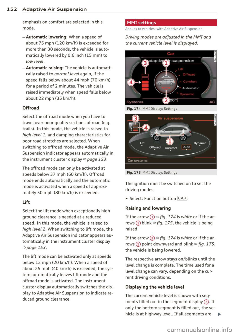
Driving modes are adjusted in the MMI and
the current vehicle level is displayed .
Fig. 174 MMI Display: Sett ings
Fig. 175 MMI Display: Settings
T he ign ition must be switched on to set the
driving modes .
.,. Select: Function button
I CAR!.
Raising and lowering
If the arrow (D Q fig. 174 is white or if the ar
rows
(D blink ¢ fig. 175, the vehicle is be ing
raised .
If the arrow @ Q fig. 17 4 is white or if the ar
rows
(D point downward and blink¢ fig. 175,
the vehicle is being lowered.
T he respective arrow stays on/blinks until the
level change is complete. The time used for a
level change can vary, depending on the cur
rent driving conditions.
Displaying the vehicle level
The current veh icle level is shown with seg
ments filled out in the segment display @. If
only the bottom segment is filled out, the ve-
hicle is at highway level.
If all segments are Ill>
Page 155 of 342
filled out, the vehicle is at high level 2 and has
the greatest amount of ground clearance pos
sib le.
Wh ile the vehicle is be ing raised or lowered,
the target level is indica ted by an arrow@
¢ fig. 174 or a white border @~ fig. 175 . The
arrow/border disappears aga in when the vehi
cle is at the target level.
Limitation s to MMI s ettin gs
Please note that not eve ry dr iving mode can
be selected in every driving situation . For ex
ample , it is not possible to switch to "lift"
mode at speeds above 12 mph (20 km/h) .
This mode is then shown
greyed out in the
MMI Display .
The vehicle can only be lowered when
a ll of
the vehicle's doors are closed. If one door is open, all driving modes whose level setting is
belo w the current vehicle level appear
greyed
out
in the MMI Display . If a door is opened
while the veh icle is being lowered , the lower
ing process is inte rrupted until all doors are
closed again.
If the system is temporarily unava ilable due
to, for instance, an empty compressed air
tank, the driving modes that cannot be set ap pear
greyed out in the MM I Disp lay. As soon
as the system is available again, the drivi ng
modes can once more be selected in the dis
p lay.
@ Tips
- For additional informat io n on the driving
modes ~
page 150, Chassis controls .
-When the compressed air tank is empty,
the comp ressor can be switched on by
starting the engine. The Adaptive Air
Suspension is once again available, after
waiting a few minutes.
- To prevent overload, the system switches off temporarily if several adjustments
are made in a row. The Adaptive Air Suspension is once again available, after
waiting a few m inutes.
Ad apti ve A ir Sus pension 15 3
Appearance in the instrument cluster
d isplay
Appl ies to vehicles: wi th Adaptive A ir Suspensio n
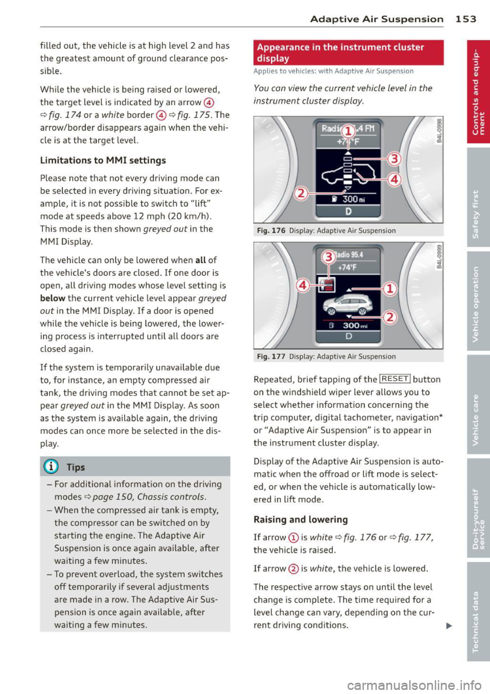
You can view the current vehicle level in the
instrument cluster display.
Fi g. 17 6 Disp lay: Adapt ive A ir Suspensio n
Fig. 177 Disp lay: Adapt ive A ir Suspension
Repeated, brief tapping of the I RESE T I button
on the windshield wiper lever allows you to
select whether information concerning the
trip computer, digital tachometer, navigat ion *
or "Adapt ive A ir Suspens ion" is to appear in
the instrument cluster d isp lay.
Display of the Adaptive Air S uspension is auto
matic when the offroad or lift mode is select
ed, or when the vehicle is automatically low
ered in lift mode.
Rai sing and lowe ring
If arrow (Dis
white¢ fig. 176 or~ fig. 177,
the vehicle is raised .
If arrow @is
white, the vehicle is lowered .
The respective arrow stays on until the level
c hange is complete. The time required for a
level cha nge can va ry, depending on the cur -
ren t driving conditions . .,..
Page 156 of 342

154 Adapti ve Air Susp en sion
Di spl ay ing the vehicl e lev el
The cu rrent vehicle level is shown w ith seg
ments fi lled out in the segment disp lay @ . If
only the bottom segment is filled out, the ve
hicle is at highway level. If all segments are
fi lled out, the vehicle is at high level 2 and has
the greatest amount of ground clearance pos
sible.
While the vehicle is being raised or lowered,
the target leve l is indicated by an arrow ©
¢
fig. 176 or a white border ©¢ fig. 177. The
arrow/border disappears aga in when the vehi
cle is at the target level.
Jacking mode when changing a flat tire
Appl ies to vehicles: with Adaptive Air Suspens ion
This mode must be activated in the MMI be
fore raising the vehicle with a jack or on a ve
hicle lift.
,. Select: Funct ion button ICARI > Function
button
! SETUP I> Jacking mode . Or
,. Select : Funct ion button
ICARI > Control but
ton
Car sy stem s* > Serv icing & ch eck s > Air
su sp .: tire ch ang e.
The vehicle jack mode must be activated be
fore changing a wheel so that the automatic
control processes for the a ir suspension do
not make lifting with the vehicle jack more dif
ficu lt.
The check lamp
II in the instrument cluster
d isplay illuminates in v ehicle jack mode.
(D) Tips
The vehicle jack mode is switched off auto
mat ically at speeds above 9 mph (15 km/
h).
Towing a trailer
Appl ies to vehicles: with towing hitch and Adapt ive Air
Suspension
Automatic lowering is not desirable when
towing a trailer.
,. Se lect: Function button ICARI > Function
button
! SE TUP I> Towi ng mod e. Or ,.
Select: Function b utton
I CAR !> Control but
ton
Car s ystem s* > Vehicle setting s > Air
su sp.: towing .
As long as towing mode is activated, a vehicle
with a trai ler appears in the
adap tiv e air su s
pen sion
main menu.
Level Ad ju stment when towing a t railer
- Before hitching up the tra ile r and before ad
jus ting the tongue weight at the trailer, the
automatic or comfo rt mode
mu st be se lect
ed so that the ve hicle can be at normal level
¢ page 152, MMI settings .
-If driving in dynamic mode is desired, this
mode
mu st be selected before hitching up
the trailer and before ad justing the tongue
weight. However, note that your vehicle is lowered and ground clearance is reduced.
- If you have to drive under difficult road con
ditions, you can select offroad or lift mode,
after hitching up the trailer or after adjust ing the tongue weight .
- If the veh icle is at
normal level, and you se
lect offroad mode wh ile traveling at speeds
higher than 22 mph (35 km/h), the veh icle
w ill not be ra ised . Offroad mode will appear
as the active mode in the MM I Disp lay.
- If the veh icle is in offroad mode at
high level
1 ,
it automa tically lowers to normal level
when the vehi cle is t ravel ing at speeds ex
ceed ing approximate ly 31 mph (SO km/h) .
The vehicle is automatically raised to
high
level 1
again when the traveling speed falls
be low approximately 25 mph (40 km/h).
Rest rictions when ope rating with a tr ailer
When operating w ith a trailer, the lift mode
can on ly be selected up to about 12 mph (20
km/h). Lift mode is automatically cance led
again w hen a speed of about 25 mph (40 km/
h) is exceeded.
If t he vehicle is in au toma tic , comfo rt, offroad
or lift mode before the trai ler towing mode is
activated, the dynamic mode cannot be acti
vated.
If t he vehicle is in dynamic mode before tow -
ing opera tion is activated, it can be driven in
11>-