AUDI RS7 SPORTBACK 2014 Owners Manual
Manufacturer: AUDI, Model Year: 2014, Model line: RS7 SPORTBACK, Model: AUDI RS7 SPORTBACK 2014Pages: 292, PDF Size: 73.56 MB
Page 111 of 292
The transmission temperature has increased
significantly due to the sporty driving manner. Drive in a less sporty manner until the tem
perature returns to the normal range and the
indicator light switches of.
[O] Transmission malfunction: You can con
tinue driving
There is a system ma lfunction in the transmis
sion. You may continue driving. Drive to your
authorized Audi dealer or qualified repair fa
cility soon to have the malfunction corrected .
[O] Transmission malfunction: You can con
tinue driving with limited functionality
There is a system malfunction in the transmis
sion . The transmission is switching to emer
gency mode. This mode only shifts into cer
tain gears or will no longer shift at a ll. The en
gine may stall. Drive to your authorized Audi
dealer or qualified repair facility immediately
to have the malfunction corrected .
[O] Transmission malfunction: Stop vehicle
and shift to P
Do not continue driving. Select the P selector
l eve r position and see you r autho rized Aud i
dealer or qualified repair facility for assis
tance.
(D Note
If the transmission switches to emergency
mode, you should take the vehicle to an
authorized Audi dealership as soon as pos
sible to have the condition corrected .
Automatic Transmission 109
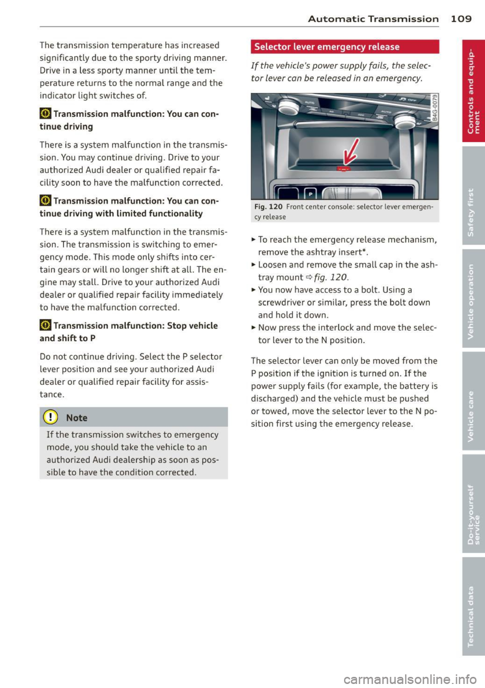
Selector lever emergency release
If the vehicle's power supply fails, the selec
tor lever can be released in an emergency.
F ig . 1 20 Fro nt center co nsole: se lector lever emerge n
cy release
.,. To reach the emergency release mechanism,
remove the ashtray insert*.
.,. Loosen and remove the small cap in the ash
tray mount
q fig. 120 .
.,. You now have access to a bolt. Using a
screwd river or similar, press the bolt down
and hold it down.
.,. Now press the interlock and move the se lec-
tor lever to the N position .
T he selector lever can only be moved from the
P position if the ignit ion is turned on . If the
power supply fai ls (for example, the battery is
discharged) and the vehicle must be pushed
or towed, move the selector lever to the N po
s ition first using the emergency release.
Page 112 of 292
110 Parking system s
Parking systems
General information
A ppl ies to vehicles: with parkin g system plus/rear view
camera/peripheral cameras
Depending on your vehicle's equ ipment, vari
ous parking a ids wi ll help you when pa rk ing
and maneuvering.
The
p ar king sy st e m plu s assists you when
pa rking by audib ly and visually indicat ing ob
jects detected
in front of and behind the vehi
cle
~ page 111.
The rear view ca m era shows the area behind
the vehicle in the Infotainment d isp lay. This
d isplay assists you when you are c ross o r par
allel parking
q page 112. In addit ion, you are
assisted by the functions from the parking
system plus
~ page 111 .
The peripher al cam era s ass ist you with park
ing and maneuvering. You are aided by var ious
cameras depending on the vehicle equipment leve l
¢page 115. In addition, you are assist
ed by the functions from the parking system
plus ¢ page 111.
A WARNING
- Always look for traff ic and check the area
around your vehicle by looking at it di
rectly as well . The parking system cannot
rep lace the d river's attent ion. The dr iver
is always respons ible for safety during
p arki ng and for all other maneuvers.
- Please note that some surfaces, such as
clothing, a re not detected by the system.
- Senso rs and cameras have blind spots in
wh ich peop le and objects ca nnot be de
te cted. Be especially cau tious of children
and animals.
- T he sensors can be displaced by impacts
or damage to the radia to r grille, bumpe r,
wheel housing and the unde rbody. The
par king systems may become impaired
as a resu lt . Have your authorized Audi
dealer or qualified workshop check their
function. -
Make s ure the sensors are not covered by
stickers, deposits or any other obstruc
tions as it may impair the sensor func
tion . For information on cleaning, refer
to
~ page 203 .
(D Note
- Some objects are not detected by the
system under certain c ircumstances:
- Obje cts su ch as ba rrie r chains, trailer
draw bars, vertical po les or fences
- Objects above t he senso rs such as wall
extensions
- Objects w ith specific surfaces or struc
tures su ch as chain link fences or pow
der snow.
- If you conti nue d riving closer to a low- ly
ing object, it may disappea r from the
sensor range. Note th at yo u w ill no lon
ger be warned abo ut this obstacle.
(j) Tips
- T he system may provide a wa rni ng even
t ho ugh the re are no obs ta cl es in the cov
erage a rea in some situa tions, such as:
- certain road surfaces or for long grass.
- externa l ultrasonic sources e.g. from
clean ing vehicles.
- heavy rain, snow or thick vehicle ex
ha ust.
- We recommend that you practice park
ing in a traff ic-free location or park ing
lot to become familiar w ith the system.
When doing this, there should be good light and weather cond itions .
- You can change the volume and pitch of
the s ignals as we ll as the disp lay
¢page 120.
- What appears in the infotainment dis
play is somewhat time-delayed .
Page 113 of 292

Parking system plus
Description
Applies to vehicles: with parking system plus
Audi parking system plus provides audio and
visual signals when parking.
Fi g. 1 21 Dis p lay f ie ld
Sensors are located in the front and rear
bumpers.
If these detect an obs tacle, visual
and in some situations aud ible signals warn
you.
M ake sure t he sensors are not cove red by
s t icke rs, deposits or a ny o ther obs truc tions as
it may impair the sensor f unction. For infor
matio n on cleaning, refer to
c::> page 203 .
The display field begins approximately at:
® 4 ft (1.20 m)
® 3 ft (0 .90 m)
© 5.2 ft (1.60 m)
@ 3 ft (0 .90 m)
The clos er you get to the obstacle, the sho rter
the interval between the audible signa ls. A
con tinuous tone sounds when the obstacle is
l ess than approximate ly 1 ft (0.30 m) away .
Do not continue driving farther¢
& in Gener
al information on page 110, ¢(Di n General
information on page 110!
If the d istance to an obstacle remains con
stant, the volume of the d istance wa rning
gradually drops after about four seconds (this
does not apply in the continuous tone range).
P arking systems 111
Switching on/off
Applies to vehicles: with parking system plus
F ig. 122 Ce nter co nso le :
Pv! button
F ig . 1 23 Infota in m ent : v is u al d is ta n ce d isplay
Switching on
.,. Shift into reverse or
.,. Press the
p,;A bu tton in the center console
c::> fig. 122 . A short confirmation tone
sounds and the LED in the button turns on .
Switching off
.,. Dr ive fo rward fas ter than 6 mph (10 km/ h),
or
.,. press the
P" IA button, or
.,. sw itch the ignit ion off.
Visual d isplay
U sing the segmen ts, yo u can estimate the dis
tance to a n object in front of o r behind the ve
hicle ¢
fig. 123 . The red lines mark the ex
pected d irect ion of travel according to the
steering ang le . A wh ite segment indicates an
identified obstacle that is outside of the vehi
cle's pat h. Red segments show identified ob
stacles that are in your vehicle's path . As your
vehicle comes close r to the obstacle, the seg
ments move closer to the vehicle . At the lat-
est th e collision area has been reached when ..,.
Page 114 of 292
112 Park in g s ystems
the next to last segment is disp layed . Obsta
cles in the collision area, includ ing those out
side of the vehicle 's path, are shown in red. Do
not continue driving farther forward or in re
verse
q .&. in General informa tion on
page 110 , q (f) in General information on
page 110 .
Rear view camera
Introduction
Applies to vehicles: with pa rkin g system p lus wit h rear
view ca mera
Fig. 124 Ill ustration: C ross pa rking
Fig. 125 Ill ustrat ion: paralle l park ing
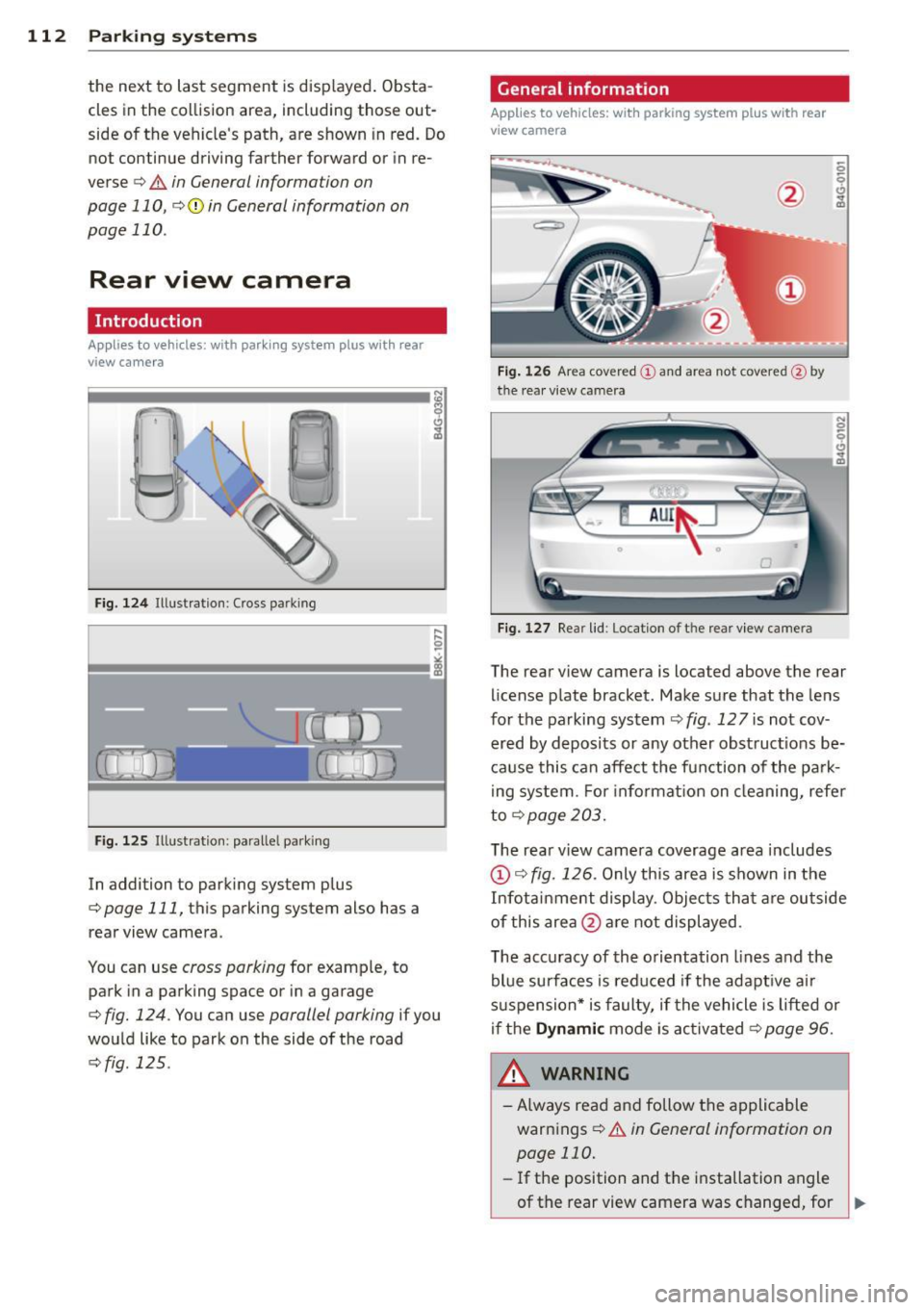
In addition to parking system p lus
q page 111, this parking system also has a
rear view camera .
You can use
cross parking for example, to
park in a parking space or in a garage
q fig. 124 . You can use parallel parking if you
wou ld like to park on the side of the road
c::> fig . 125 .
General information
Applies to vehicles : wit h parking system plus with rear
v iew camera
Fig. 1 26 Area cover ed © and area not cover ed@ by
the rea r view ca mera
F ig. 127 Re ar lid: Location o f th e rear view camera
N 0 q
Cl
~
The rear v iew camera is located above the rear
license plate bracket. Make sure that the lens
for the parking system
c::> fig . 12 7 is not cov
ered by deposits or any other obst ruct ions be
ca use this can affect the fun ction of the park
i ng system. For informat ion on cleaning, refer
to
q page 203.
The rear v iew camera coverage area includes
@ c::> fig. 126 . Only this area is shown in the
Infot ainment display . Objects tha t are outside
of this area @are not displayed .
The accuracy of the orientation lines and the
blue surfaces is reduced if the adapt ive a ir
suspension* is faulty, if the vehicle is lifted or
if the
Dynam ic mode is activa ted c::> page 96.
A WARNING ~
-Always read and follow the applicable
warnings
c::> .&. in General information on
page 110.
- If the position and t he installation angle
-
of the rear view camera was changed, for IJl>
Page 115 of 292

example, after a collision, do not contin
ue to use the system for safety reasons.
Have it checked by your authorized Audi
dealership or authorized repa ir facility .
- Only use the rear v iew camera to assist
you if it shows a good, clear picture. For
example, the image may be affected by
the sun shin ing into the lens, dirt on the
lens or if there is a system fau lt.
- Use the rear view camera only if the lug
gage compartment lid is comp letely
closed. Ma ke su re any objects you may
h ave mounted on the luggage compart
ment lid do not block the rear view cam
era.
- The camera lens en la rges and dis torts
the field of vision. The ob ject appears
both a ltered and inaccurate on the
screen .
- In certain s ituations, peop le or objects in
the display appear closer or f urther
away:
- For objects that do not touch the
ground , such as the bumper of a
pa rked vehicle, a t railer hitch or the
rea r of a truck. Do not use the help
lines in this case.
- If driven from a leve l su rface onto a n
incline, or a downward slope.
- If driven towa rd p rotruding objects.
- If the veh icle is ca rrying too much load
in the rear.
(D Note
- Always read and follow the applicable
warnings
¢ (D in General information on
page 110.
- The orange colored orientat ion lines in
the Infotainment d isplay show the vehi
cle path depending on the steering
whee l ang le. The front of the vehicle
front sw ings out more than the rear of
the veh icle. Mainta in p lenty of distan ce
so that your outside mirro r o r a corne r of
you r vehicle does not collide with any ob
stacles.
Par king sys tem s 113
Switching on/off
App lies to vehicles: wit h parking system plus w ith rear
v iew camera
Switching on
.. Shift in to reverse or
.. press the
PwA bu tton in the center console
¢ page 111, fig . 122 . A short confirmation
tone sounds and the LED in the button turns
on .
Swi tching between the re ar view camera
and optical display
.,. Press the Graphi c control button®
¢ page 114, fig. 128 to see the optical d is
play .
.. Press the
Rearview control b utton to see the
rear view camera image.
Switching off
.,. Dr ive forward faster than 6 mph (10 km/h),
or
.. Press the
p,,1A button, or
.,. Switch the ignit ion off.
(D Tips
The visual d isplay in the left part of the
display should help you detec t the critical
vehicle areas .
Page 116 of 292
114 Parking systems
Cross parking
Applies to vehicles: with park ing system p lus w it h rear
view ca mera
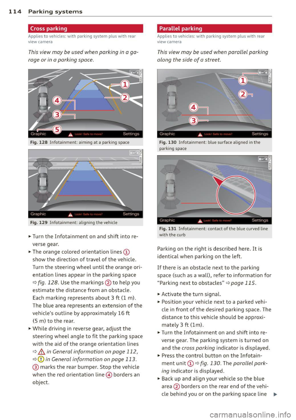
This view may be used when parking in a ga
rage or in a parking space.
F ig. 128 Infotainment: aim ing at a parking space
Fig. 129 Infotainment : aligning the ve hicle
... Turn the Infotainment on and shift into re
verse gear.
... The orange colored orientation lines
(D
show the direction of travel of the vehicle.
Turn the steering wheel until the orange ori
entat ion lines appear in the parking space
c:::> fig. 128. Use the markings @to help you
est imate the distance from an obstacle.
Each marking represents about 3 ft (1 m).
The blue area represents an extens ion of the
vehicle's out line by approximately 16 ft
(5 m) to the rear.
... While driving in reverse gear, adjust the
steering wheel angle to fit the parking space
with the aid of the orange orientation lines
c:> & in General information on page 112,
c:::> @ in General information on page 113 .
@ marks the rear bumper . Stop the veh icle
when the red orientation line@ borders an
object.
Parallel parking
Applies to vehicles : wit h parking system pl us with rear
v iew camera
This view may be used when parallel parking
along the side of a street.
Fig . 130 Infotainment : blue surface aligned in the
park ing space
Fig. 131 Infotainme nt: contact of the blue curved lin e
w ith the curb
Parking on the right is described here. It is
identical when parking on the left.
If there is an obstacle next to the parking
space (such as a wall), refer to information for
"Parking next to obstacles"
c:::> page 115.
"' Activate the turn signal.
"'P osit ion your veh icle next to a parked vehi
cle in front of the desired parking space. The
distance to this vehicle should be approxi
mate ly 3 ft (lm) .
... Turn the Infotainment on and shift into re
verse gear . The parking system is turned on
and the
cross parking indicator is displayed.
"' Press the control button on the Infota in
ment un it
(D c:::> fig. 130 . The parallel park
ing
indicator is displayed.
"' Back up and align your vehicle so the blue
area @borders on the rear end of the veh i-
cle behind you or on the parking space line ..,.
Page 117 of 292
r::> & in General information on page 112,
r::>(D in General information on page 113 .
The blue area represents an extens ion of the
vehicle's outline by approximately 16 ft
(5 m) to the rear . The long side of the blue
area should be on the curb . The entire blue
area must fit into the parking space.
• With the veh icle stopped, turn the steering
wheel to the right as far as it w ill go.
• Back in to the park ing space u ntil the b lue
curve
r::> fig . 131 touches the curb r::> & in
General information on page 112,
r::> (D in
General information on page 113 .
Stop the
vehicle.
• With the veh icle stopped , turn the steer ing
whee l to the left as far as it will go .
• Continue to back into the parking space un
t il the vehicle is parked pa rallel to the cu rb
r::> & in General information on page 112,
r::> (D in General information on page 113 .
@ marks the rear bumper. Stop the veh icle,
at the latest, when the red orientation line
@ borders an object. Keep an eye on the
front of your vehicle whi le do ing th is .
Pa rking next to obstacles
If there is an obstacle (s uc h a s a wall) next to
the par king space, position the veh icle so
there is more space o n that s ide. Position the
l ong side of the blue s urface so that there is
sufficient space from the obstacle . The sur
face must not be to uch ing . You will also need
to star t turning the steer ing wheel much ear
lier . The blue curve
r::>fig .131 must not touch
the obstacle and should have sufficient room.
(D Note
Remember to maintain sufficient clear
ance from the curb to avoid damag ing the
wheel rims .
(D Tips
The left or right orientation lines and sur
faces will be displayed, depend ing on the
turn sig na l being used.
P arking systems 115
Peripheral cameras
Introduction
Applies to vehicles: with parking system plus with periph
eral cameras
In add ition to parking system plus
¢
page 111, this parking system conta ins pe
ripheral cameras . Depending on the vehicle
equipment , you are ass isted by vario us views
su ch a s p eriphera l view, corne r views a t the
fron t and rear of the veh icle, and views di rect
ly in front of or behind t he vehicle .
General information
Applies to vehicles: with parking system plus with periph
eral cameras
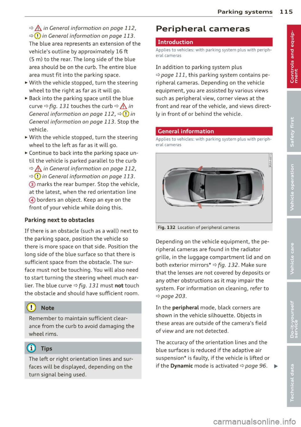
F ig . 1 32 Locat io n of per ip hera l ca meras
Depending on the vehicle equipment, the pe
ripheral cameras are found in the radiator
grille, in the luggage compartment lid and on
both exterior mirrors* ¢
fig. 132. Make su re
that the lenses a re not covered by depos its o r
any other obstr uctions as it may impa ir t he
system. For info rmat io n on clean ing, refe r to
¢ page 203.
In the peripheral mode , b lack corners are
shown in the ve hicle silhouette . Objects in
these a reas a re outside of the came ra's field
of view and are not detec ted .
The accuracy of the orientation lines and the
bl ue surfaces is reduced if the adaptive a ir
suspension* is faulty, if the vehicle is l ifted or
if t he
D ynamic mode is activa ted ¢ page 96. ..,.
Page 118 of 292
116 Parking systems
& WARNING
- Always read and follow the applicable
warnings
Q .&. in General information on
page
110.
- If the posit ion or the installation angle
of a camera was changed, afte r a colli
sion for example, do not continue to use
the system for safety reasons. Have it
checked by your au thori zed Audi dealer
s hip.
- K eep in m ind that the image i n the dis
play is distorted if the ex ter ior mir ro r
housing has been man ual ly adjusted .
- Use the
re ar mode and the corner view
(re ar)
mode on ly when the luggage com
partment lid is fully closed . Otherwise
the image in the display will be distort
ed.
- The veh icle surroundings are shown us
ing the camera images . The vehicle im
age is shown by the system. Objects and
obstacles above the camera are not dis
played .
- Camera lenses en large and distort the
field of v is ion. The objects appear both
altered and inaccu rate on the screen.
(D Note
- Always read and follow the applicab le
warnings
c:> (i) in General information on
page
110.
- The In fota inment display shows the d i
rection in wh ich the rear of the vehicle is
traveling based on the steering wheel
angle . The front of the ve hicle front
swings out more than the rear of t he ve
hicle. Ma intain plenty of distance so that
you r outside m irror or a corner of you r
vehicle does no t coll ide wi th any obsta
cles.
@ Tips
I f t he 8/cr;iJ/r:;::::s symbol appea rs i n the
d isp lay and the respec tive display area is
g rayed out, then the power exter io r mir
rors were fo lded in or the driver 's door/ front passenger's door/
luggage compart
ment lid was opened.
Switching on or off
Applies to vehicles: with parking system plus with periph
eral cameras
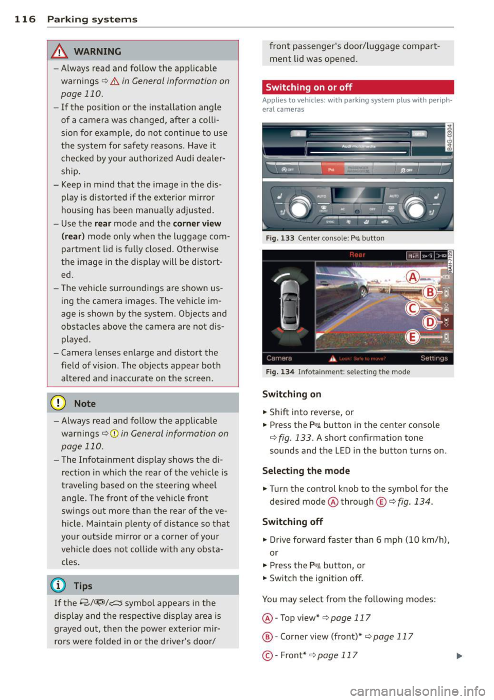
Fig . 1 33 Ce nte r co n sole: f> •JI butto n
Fig. 1 34 Infot ainment: se lect ing t he m od e
Switching on
.. Shift into reverse , or
.. Press the P•QJ\. button in the cente r console
c:> fig. 133 . A short confirmation tone
sounds and the L ED in the button turns on .
Selecting the mode
.. Turn the control knob to the symbol fo r the
desired mode @ through @¢
fig. 134 .
Switching off
.. Dr ive fo rward faster than 6 mph (10 k m/ h),
or
.. Press the
P"li bu tton, or
.. Switch the ignit ion off .
You may sele ct from the following modes:
@ -Top view*
c:>page 117
@ -Corne r view (front)* c:> page 11 7
©-Front * c:>page 117
Page 119 of 292
@-Rear* ¢ page 118
© - Corner view (rear)* ¢ page 117
Top view
Applies to vehicles: with parking system plus and top view
mode
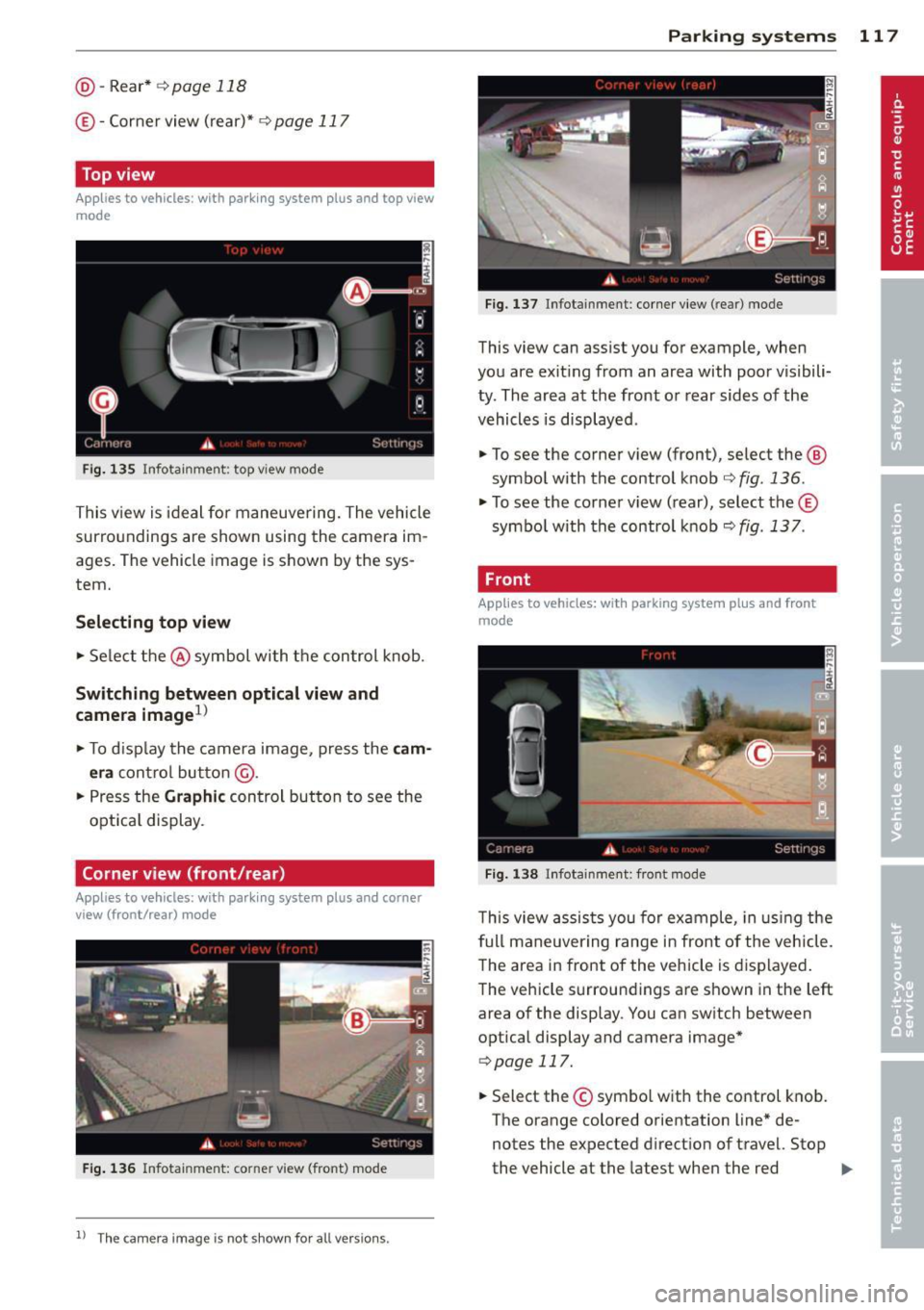
Fig . 135 Infotainment: top view mode
This view is ideal for maneuve ring. The vehicle
surro undings are shown using the camera im
ages. The vehicle image is shown by the sys
tem.
Selecting top view
~ Select the @symbol with the control knob.
Switching between optical view and
camera image
1
)
~ To display the camera image, press the cam
era
contro l button @ .
~ Press the Graphic control button to see the
opt ica l display.
Corner view (front /rear )
Applies to vehicles: with parki ng system plus and corner
view (front/rear ) mode
Fig. 136 Infotainment: corner view (front} mode
1 1
Th e ca mera image is not s hown for all ve rsio ns.
Parking systems 117
Fig. 137 Infotainment: corne r view (rear) mode
This view can assist you for example, when
you are exit ing from an area with poor visibili
ty. The area at the front or rear sides of the
vehicles is displayed .
~ To see the corner view (front), select the @
symbol with the control knob¢
fig. 136.
~ To see the co rner v iew ( rear), select the©
symbo l with the control knob¢
fig. 137.
, Front
Applies to vehicles: with parking system plus and front
mo de
Fig. 138 ln fotainment: front mode
This view assists you for example, in using the
full maneuvering range in front of the vehicle.
The area in front of the vehicle is displayed.
The vehicle s urround ings are shown in the left
area of the display. You can switch between
optical display and camera image*
qpag e 117.
~ Select the © symbo l with the control knob .
The orange colored orientation line* de
notes the expected direction of travel. Stop
the vehicle at the latest when the red
Iii>-
Page 120 of 292
118 Parking systems
orientation line * borders an object¢.&. in
Gen eral information on page 116 .
Rear
Appl ies to vehicles: with parking system plus and rear
mode
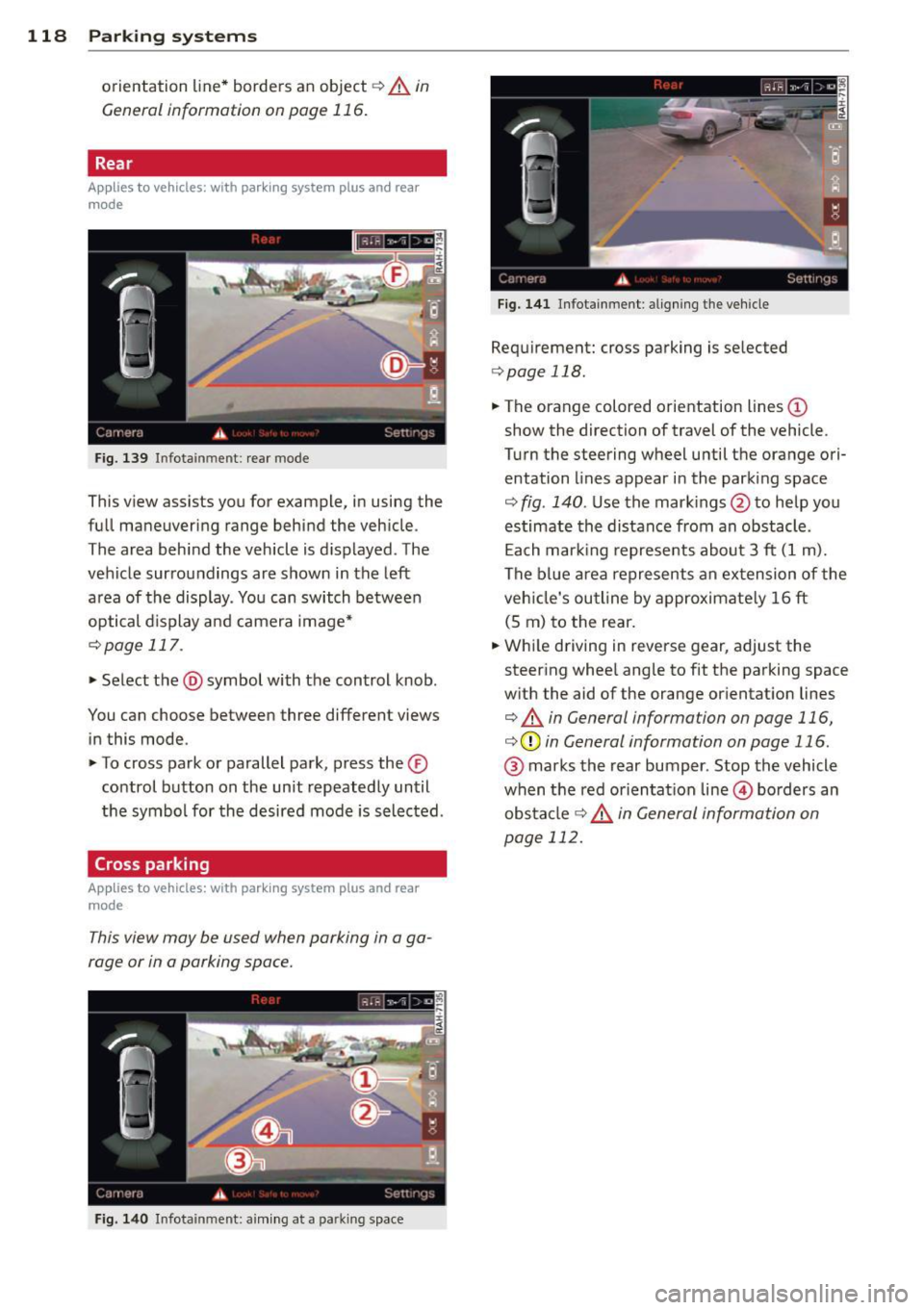
F ig. 139 In fot ainm ent: rear mode
Th is view as sists you for example, in using the
f ull maneuvering range behind the veh icle .
The area beh ind the veh icle is d isplayed . The
vehicle surroundings are shown in the left
area of the display . You can switch between
optical d isplay and camera image*
¢ page 117.
.,. Select the @symbol with the control knob .
You can choo se between three different views
in this mode .
.,. To cross park or parallel park, press the ®
control button on the unit repeated ly until
the symbol for the desired mode is selected .
Cross parking
Applies to vehicles: with parking system p lus and rear
mode
T his view may be used when parking in a ga
rage or in a parking space.
Fi g. 140 Infot ainment: a im ing at a parkin g space
Fig . 14 1 Info ta inme nt: al ign ing t he ve hicle
Requ irement: cros s parking is selected
¢ page 118 .
.,. The orange colored orientation lines(!)
show the direction of travel of the vehicle .
Turn the steering wheel until the orange ori
entation lines appear in the parking space
¢ fig . 140 . Use the mark ings @to help you
estimate the distance from an obstacle .
Ea ch mar king represe nts about 3
ft (1 m).
The blue area represents an ex tension of the
veh icle's ou tline by approximate ly 16 ft
(S m) to the rear.
.,. Whi le driving in reverse gear, adjust the
steer ing whee l angle to fit the parking space
w ith the aid of the orange orientat ion lines
¢ .&. in General information on page 116,
¢ (Din General information on page 116 .
@ marks the rear bumper. Stop the vehicle
when the red orienta tion line @ borders an
obs ta cl e
¢ .&. in General information on
page 112.