ECU AUDI RS7 SPORTBACK 2015 Owner's Guide
[x] Cancel search | Manufacturer: AUDI, Model Year: 2015, Model line: RS7 SPORTBACK, Model: AUDI RS7 SPORTBACK 2015Pages: 302, PDF Size: 74.76 MB
Page 181 of 302
M N
0:: <.J 'SI: ,...., \!) 1.1"1 ,...., 1.1"1 ,....,
If the convertible locking retracto r shou ld be
activated inadvertently, the safety belt must be unfastened and guided comp letely back in
to its stowed position to deactivate th is fea
ture. If the co nvertible locking retractor is not
deactivated, the safety belt will gradually be
come tighter and u ncomfortable to wear.
A WARNING
Improperly insta lled child safety seats in
crease the risk of ser ious personal inju ry
and death in a collision.
- Never unfasten the safety belt to deacti
vate the convert ible lock ing ret ra ctor for
child restrain ts w hile the veh icle is mov
ing. You would not be rest rained and
cou ld be seriously injured in an accident.
- Always read and heed all WARN INGS
whenever using a child rest rained in ave
hicle is being used
c:!) page 165. Spec ial
precautions apply when installing a ch ild
safety seat on the front passenger seat
c:!) page 141, Child restraints on the front
seat -some important things to know.
LATCH Lower
anchorages and tethers
for children
Child Restraint System anchors and how
are they related to child safety
To provide a s impler and more pract icable way
to attach the child restraint on the vehicle
seat, Federa l regu lations require specia l lower
anchorages in vehicles and devices on new
chi ld restraints to attach to the vehicle ancho
rages.
The combination of the tether anchorages and
the lower anchorages is now generally called
the
LAT CH system for " Lower Anchorages and
T ethers for Children."
F orward-facing child restraints manufactured
after September 1, 1999, are required by U.S.
federal regulations to comply with new child head movement performance requirements.
Child Sa fet y 1 79
These new performance requirements make a
tether necessary on most new child seats.
Installing a ch ild restra int that requires a top
tether without one can seriously impair the
performance of the child restraint and its abil
ity to protect the child in a collision . Insta lling
a chi ld restraint that requires a top tether
without the top tether may be a violat ion of
state law.
Child restraint manufacturers offer LA TCH
l ower anchorages on their child seats w ith
hook-on or push-on connectors attached to
adjustable straps.
In addition to the LATCH lower anchorages,
these chi ld restraint systems usually require
the use of tether straps to he lp keep the child
restraint f irmly in place.
A WARNING
Improper installat ion of child restra ints
will increase the r isk of injury and death in
a crash.
- Always follow the instructions provided
by the manufacturer of the child re
straint you intend to install in your vehi
cle.
- Never install a child restraint without a
properly attached top tether strap if the
child restraint manufacturer's instruc
tions require the top tether st rap to be
used .
- Improper use of child restraint LATC H
lower anchorage points can lead to injury
in a collision. The LATCH lowe r anchorage
points are designed to withstand on ly
those loads imposed by correctly fitted
child restraints.
- Never mo unt two child restraint systems
on one LATCH lower anchorage point.
- Never secure or attach any luggage or
other item to the LATCH lower anchorag
es.
-
•
•
Page 182 of 302
180 Child Safet y
@ Tips
-In Canada, the terms "top tether" with
"lower universa l anchorages" (or "lower
universal anchorage bars") are used to
describe the system.
- In other countries, the term "ISO FIX" is used to describe the lower anchorages.
Location
Fig . 174 Schemat ic overview: LA TCH ancho rage point
l ocat ions
The illustration shows the seating locations in
your veh icle which are equipped w ith the low
e r anchorages system.
Description
The lower anchorage positions are marked
for quick locating .
Fig. 175 Lower a nch orages, covers marked
Fig. 176 Rea r seats: lowe r ancho rage b racket locat ions
L o w er an ch orage s
The circular markings on the rear seat help
you to ident ify the location of lower anchorag
es for the two outboard seating positions
~ fig . 175. The LATCH lower unive rsal ancho r
age a ttachment po ints are between the rear
seatback and rea r seat cushion .
Remove the covers~
fig. 175 to access the
lower anchorage attachment points.
The lower anchorage attachment points are
vis ible
c:> fig . 176 .
Lower anchorages secure the chi ld restraint in
the seat without using the vehicle 's safety
belts. Anchorages provide a secure and easy
to -use attachment and minimize the possib ili
ty of improper child rest ra int installation .
All child restraints manufactured after Sep
tember 1, 2002, must h ave lower anchorage
attachments for the
LATCH system .
Please remember that the lower anchorage
po ints are only intended for installat ion and
attachment of child restraints spec ifically cer
tified fo r use with
LATCH lower anchorages .
Child rest raints that are not equ ipped with the
lower anchorage attachments can still be in
sta lled in compliance w ith the ch ild restra int
manufactu rer's instr uctions on using veh icle
safety belts .
A WARNING
-
Improper use of LATCH lower anchorages
can cause serious persona l injury in an ac
cident.
- Always carefu lly follow the child re
straints manufacturer's instructions for
Page 183 of 302
"' N
a:: I.J "". rl I.O
"' ......
"' rl
proper installation of the child restraint
and proper use of the lower anchora ges
or safety belts in your vehicle.
- Never secure or attach any luggage or
other items to the LATCH lower ancho
rages.
- Always read and heed the important in
formation about child restraints in this
chapter and WARNINGS¢
page 165,
Child Safety.
Installing a child restraint with LATCH
lower anchorages
Whenever you install a child restraint always
follow the child restraint manufacturer's in
structions.
Fig. 177 Lower anchorages: p roper mo unting
Mounting
.. Make sure the seatback of the rear seat
bench is in the upright position and securely
latched in place.
.. Attach both hook-on connectors with the
spring catch release on the child safety seat
onto the LATCH lower anchorage so that the
connectors lock into place¢
fig. 177 .
.. Pull on the connector attachments to make
s ure they are properly attached to the LATCH
lower anchorage .
.. Pull straps tight following the child restra int
manufacturer's instructions.
Releasing
.. Loosen the tension on the straps following
the child restraint manufacturer's instruc
tions .
Child Safety 181
.. Depress the spring catches to release the
anchorage hooks from the lower anchorag
es.
Remember: Use tether straps to help keep the
child restraint firmly in place.
& WARNING ~
Improper use of the LATCH system can in-
crease the risk of serious personal injury
and death in an accident.
- These anchors were developed only for
child safety seats using the "LATCH" sys
tem.
- Never attach other child safety seats,
belts or other objects to these anchors.
- Always make sure that you hear a click
when latching the seat in place. If you do
not hear a click the seat
is not secure and
could fly forward and hit the interior of
the vehicle, or be ejected from the veh i
cle .
& WARNING
Improper installat ion of child restraints
will increase the risk of injury in an acci
dent.
- Always follow the child restraint system
manufacturer's instructions for proper
installation of the child restraint system
and proper use of tether straps as well as
the lower anchorages or safety belts in
your vehicle .
-Always read and heed the important in
formation and WARNINGS about child safety and the installation of child re
straint systems¢
page 165, Child Safe
ty.
-
Page 184 of 302
182 Child Safet y
Tether anchors and tether straps
Fig. 178 Tethe r ancho rs: attachment hook locat io ns
behind the rea r sea tbacks
The tethe r anchors for the rear sea ting posi
tions are located on the backside of the rea r
seatbacks
~ fig. 178.
A tether is a straight or V-shaped strap that
attaches the top part of a child restraint to
specia l anchorage points in the veh icle.
The purpose of the tether is to reduce the for·
ward movement of the ch ild restra int in a
crash, in order to he lp reduce the r isk of head
in ju ry that could be ca used by s tri king the ve
hicle interior.
Forward facing child restra ints manufactured
after September 1, 1999, a re required by U .S .
federal regulations to comply with new child
head movement performance requirements.
These new performance requ irements make a
tether necessary on most new chi ld safety
seats.
A WARNING
Improper insta llation of chi ld restraints
w ill increase the risk of injury and death in
a crash.
- Always follow the instructions prov ided
by the manufacturer of the ch ild re
st ra int you intend to install in your Audi.
- Improper use of c hild restra int anchors
(including tether anchors) can lead to in ·
jury in a co llision. Th e anchors are de·
sign ed to withstand only those loads im
posed by cor rect ly fi tted ch ild restraints.
- Never mou nt two chi ld restraint systems
on one LA TCH lower anchor po int. -
Never attach two child restraint systems
to one tether strap or tether ancho rage.
- Never attach a tether strap to a tie-down
hook in the luggage compartment.
- Never use child restraint tether ancho
rages to secure safety belts or other
kinds o f occupant restraints.
- Never secure or attac h any luggage or
other items to the LATCH lower ancho
rages or to the tether anchors.
- If you must install a rearwa rd facing
chi ld safety seat on the front passenger
seat because of exceptiona l c ircumstan
ces and the
PASSENGER AIR BAG OFF
light does not come on and stay on, im
mediately insta ll the rear-fac ing ch ild
safety seat i n a rea r seating position and
h ave the air bag system ins pe cte d by your
Au di dea le r.
Installing the upper tether strap on the
anchorage
F ig . 1 79 Tet her st rap: prope r rou ting and mou nting
Installing the tether strap
.,. Release or deploy the tether st rap on the
child res traint accord ing to t he child re
s traint manufa cturer's instructions.
.,. Guide the upper te ther s trap unde r or side
ways o f the rear head restraint~
fig. 179
(depending on the c hild restraint) .
.,. Attach the tether strap anc horage hook into
the tether anchorage.
.,. Pull on the tether strap hook so that the
spring catch of the hook engages .
.,. Tighten t he tether strap firmly fol low ing the
child r estraint manufacture r's instructions .
liJJ,
Page 214 of 302
212 Check ing and filling
- Always disconnect the battery.
- Never smoke or work near heaters or open flames . Fluids in the engine com
partment could start a fire.
- Keep an approved fire extinguisher im
mediately available.
- To avoid electrical shock and persona l in
jury while the engine is running or being started, never touch:
- Ignition cables
- Other components of the high voltage
electronic ignition system.
- If you must perform a check or repa ir
with the engine running:
- Fi rst, fully apply the parking bra ke,
move se lec to r lever to P (Pa rk) .
- Always use extreme caution to preven t
clot hing, jewe lry, or long h air from ge t
ting caught in the radiator fan, V -belts
or other moving parts, or from contact ing hot parts. Tie back hair before
start ing, and do not wear cloth ing that
will hang or droop into the eng ine.
- Min imize exposure to emission and
chemica l hazards¢ ,&..
A WARNING
California Propos ition 65 Warning:
- Engine exhaust, some of its constituents,
and certa in veh icle components conta in
or emit chemicals known to the State of
Califor nia to cause cancer and b irth de
fec ts a nd reproduct ive ha rm. In addition,
certain fluids conta ined in vehicles and
certa in prod ucts of co mponent wear co n
ta in o r emi t chemicals known to the
State o f Ca lifornia to cause can cer and
birth defects or ot her reproductive harm. -
Battery posts, terminals and re lated ac
cessories conta in lead and lead com
pounds, chemicals known to the State of
California to cause cance r and reproduc
tive harms. Wash hands after handling .
(D Note
When adding flu ids, always make sure that
they are poured into the proper conta iner
or f iller opening, otherwise serious dam
age to vehicle systems w ill occur.
® For the sake of the environment
To detect leaks in time, inspect the vehicle
floor pan from underneath regularly. If
you see spots from oil or other ve hicle flu
i ds, have yo ur vehicle inspected by a n au
thori zed Audi dea le r.
Closing the engine hood
.,. Pull the hood down un til the pressure from
t he struts is reduced.
.,. Let the hood drop down and latch in p lace .
Do not try to push it shut; it may fail to en
gage ¢&_ .
A WARNING
-
A hood that is not completely latched
could fly up and b lock your view while dr iv
ing.
- When you close the engine hood, check it
to make sure the safety catch has p roper
ly engaged. The hood sho uld be flush
with the surrou nding vehicle body pa rts.
- If you notice while driv ing t hat the hood
is not s ecured prope rly, stop at onc e and
close it.
Page 242 of 302
240 Tires and wheels
the driver observe the speci
fied tire pressure values for
the tires and the correct pressures for the function of
the tire pressure monitoring
system.
-Always inflate tires to the
recommended and correct
tire pressure before driving
off.
-Driving with underinflated tires bend more, letting
them get too hot resulting
in tread separation, sudden
tire failure and loss of con
trol.
-Excessive speed and/over
loading can cause heat
build-up, sudden tire failure
and loss of control.
-If the tire pressure is too low or too high, the tires
will wear prematurely and
the vehicle will not handle
well.
-If the tire is not flat and you do not have to change a
wheel immediately, drive at reduced speed to the near
est service station to check
the tire pressure and add air
as required.
(D Note
Driving without valve stem
caps can cause damage to
the tire valves. To prevent
this, always make sure that
factory installed valve stem
caps on all wheels are securely mounted on the valve.
@ For the sake of the environment
Underinflated tires will also
increase the fuel consump
tion.
Tires and vehicle load limits
There are limits to the amount
of load or weight that any vehi
cle and any tire can carry. Ave hicle that is overloaded will not
handle well and is more diffi
cult to stop. Overloading can
not only lead to loss of vehicle
control, but can also damage
important parts of the vehicle
and can lead to sudden tire fail
ure, including a blowout and
sudden deflation that can cause
the vehicle to crash.
Your safety and that of your passengers also depends on
making sure that load limits are~
Page 256 of 302
254 Tire s and wheel s
Wheel bolts
Wheel bolts must always be tightened to the
correct torque .
The design of wheel bolts is matched to the
factory installed rims. If different rims are fit
ted, the correct wheel bolts with the r ight
length and correctly shaped bolt heads must
be used. This ensures that wheels are fitted
secure ly and that the brake system funct ions
correctly .
In ce rtain circumstances, you may not use
wheel bolts from a different vehicle -even if it
i s the same mode l
~page 284.
_& WARNING
Improperly tig htened o r maintained whee l
bolts can become loose ca using loss of
contro l, a co llision and serious persona l in
jury.
- Always keep the wheel bolts and the
threads in the wheel hubs clean so the
wheel bolts can turn easily and be prop
erly t ightened.
- Never grease or oil the wheel bo lts and
the threads in the wheel hubs. They can
become loose while driving if greased or
oiled, even if tightened to the specif ied
torque.
- Only use wheel bolts that belong to the
rim being installed.
- Never use different wheels bolts on your
vehicle.
-Always maintain the correct tighten ing
torque for the wheel bo lts to reduce the
risk of a wheel loss. If the tightening tor
que of the wheel bolts is too low, they
can loosen and come out when the veh i
cle is moving. If the tightening torque is
too high, the whee l bolts and threads
can be damaged and the wheel can be
come loose.
@ Note
The spec ified torque fo r the wheel bo lts is
90 ft lb (120 Nm) w ith a tolerance of± 7,4
ft lb(± 10 Nm). Torque wheel bo lts diago- nally
. After changing a whee l, the torque
must be checked as soon as possible with a
torque wrench -preferably by an author
i zed Audi dealer or qualified workshop.
Low aspect ratio tires
Your Audi is factory-equ ipped w ith low aspect
ratio tires . These tires have been thoroughly
tested and been selected specifically fo r your
model for their superb perfo rmance, road fee l
and hand ling under a variety of d riving cond i
tions . As k your au thor ized A udi dealer for
more details .
T he low aspect ratio of these tires is ind icated
by a numera l of
55 or less in the tire's s ize
designation. The numera l represen ts the ratio
of the tire's sidewall height in relation to its
tread width expressed in percentage . Conven
tiona l tires have a height/width ratio of 60 or
more.
The perf orm ance of low- aspect-r atio tire s is
p ar ticu larly s ensitive to improper infl ati on
press ure . It is t here fore im portant that low
as pect rat io tires are infl ated to the spe cified
pre ssure and that the infl ation pressu re is
r e gularl y che ck e d and mainta in ed. Tire pre s
su res should b e check ed at least onc e a
month and alwa ys bef ore a long trip
~page 237, Checking tire pressure.
What you can do to a void tire and rim
damage
Low aspect ratio tires can be damaged more
easily by impact w it h potholes, curbs, gull ies
o r r idges on the road, pa rticularly if the tire is
u nderinfla ted .
In order to minimize the occurrence of impact
damage to the tires of you r vehicle, we recom
mend that you observe the follow ing p recau
tions:
- Always ma inta in recommended inflation
pressures. Check your tire pressure eve ry
2,000 miles (3,000 km) and add air if neces
sary .
- Dr ive carefully on roads with potholes, deep
gullies o r ridges. The impact from dr iv ing ..,.
Page 261 of 302
"' N
a:: I.J "". rl I.O
"' rl
"' rl
What do I do now? Emergency warning
triangle
App lies to vehicles: with emerge ncy warning triangle
The warning triangle is located on the inside
of the trunk lid .
D -
!I l
Fig. 203 Trun k lid: Warn ing triang le
.,. To open the cover, turn the locking mecha
nism and pull the cover downward . "'
M ~
~ .. m
.,.
Remove the warning triangle from its hold
er .
The rear lid is only designed to ho ld the warn
ing triangle offered by the original accessories
program. If you would like to retrofit your ve
hicle with a warning triangle, p lease contact
your authori zed Audi dealer.
Vehicle tool kit
Vehicle tool kit and jack
The vehicle tool kit is located in the luggage
compartment under the cargo floor cover.
F ig . 204 Trunk lid: V eh icl e too l kit
.,. Fold the floor to the seatback with the help
of the handle .
What do I d o now ? 259
.,. Turn the handwheel counter-clockwise and
remove the cover to reach the vehicle tool
kit .
T he onboard too l kit includes:
- T ire repair kit ( Tire Mobility System)
- Hooks to remove the wheel covers*
- Plastic hook to remove wheel bolt covers*
- Wheel bolt wrench
- Alignment pin for changing wheels
- Screwdriver with reversib le blade
- Tow ing eye
- Jack
Before storing the jack, make sure it is wound
back down as far as it will go.
A WARNING
Imp roper use of the vehicle jack can ca use
serious pe rsonal injur ies.
- Never use the screw driver hex head to
tighten wheel bo lts, since the bolts can
not attain the necessary tighten ing tor
que if you use the hex head, potentially
causing an ac cident .
- The fac tory-supplied jack is intended on
ly for yo ur vehicle model. Under no c ir
cumstances should it be used to lift
heavy vehicles or other loads; you risk in
juring yourself.
- Never start the engi ne when the vehicle
is raised, which could cause an acc ident.
- Support the vehicle securely with appro
priate stands if work is to be performed
underneat h the vehicle ; otherwise, there
is a potentia l risk for injury.
- Never use the jack supplied wit h your
Audi on another vehicle, particularly on a heav ier one. The jack is only su itable for
use on the veh icle it came with.
@ Tips
- Some of the on board items listed above
are provided on certa.in models only or
are opt ional extras.
- Before you can raise your vehicle using
the jack, you must activate the jacking
mode¢
page 265 .
Page 268 of 302
266 What do I do now?
Position the vehicle jack only under the desig
nated lifting points on the sill
r::!;> fig. 210.
There is exactly one location for each wheel.
The jack must not be positioned at any other location¢ ,&.¢(D .
An
un stable surfa ce under the jack can cause
the vehicle to slip off the jack. Always prov ide
a firm base for the jack on the ground. If nec
essary place a sturdy board or similar support
under the jack . On
hard, slippery surfaces
(such as tiles) use a rubber mat or sim ilar to
prevent the jack from slipping¢.&..
A WARNING
-You or your passengers could be injured
wh ile chang ing a wheel if you do not fol
low these safety precautions:
- Position the vehicle jack only at the
designated lifting points and align the
jack . Otherwise, the vehicle jack could
slip and cause an injury if it does not
have sufficient hold on the vehicle.
-A soft or unstable surface under the
jack may cause the veh icle to slip off
the jack. Always provide a firm base for
the jack on the ground.
If necessary,
use a sturdy board under the jack.
- On hard, slippery surface (such as tiles)
use a rubber mat or sim ilar to prevent
the jack from s lipping.
- T o help prevent injury to yourself and
yo ur passenge rs:
- Do not raise the vehicle unti l you are
sure the jack is securely engaged.
- Passengers must not remain in the ve
hicle when it is jacked up.
- Make sure that passengers wait in a
safe p lace away from the vehicle and
well away from the road and traffic.
- Make sure jack position is correct, ad
just as necessary and then continue to ra ise the jack.
- Changes in temperature or load can af
fect the height of the vehicle.
(D Note
Do not lift the vehicle by the sill. Position
the veh icle jack only at the designated lift
ing points on the sill. Otherwise, your vehi
cle will be damaged.
(D Tips
The vehicle jack mode * switches off auto
matically at speeds above 6 mph (10 km/
h).
Removing and installing the sill cover
Applies to vehicles: with sill
Fig. 212 Sill: remov ing the cover
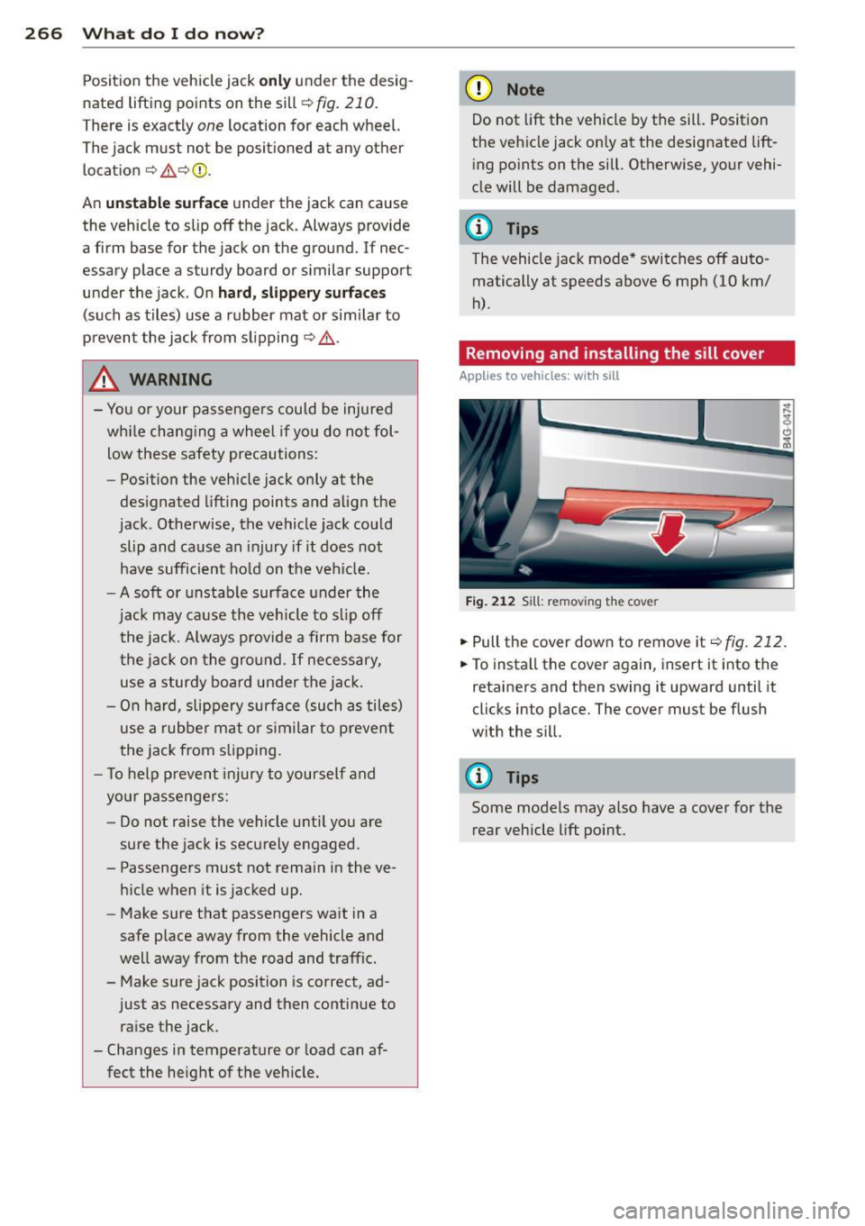
.. Pull the cover down to remove it¢ fig. 212.
.. To install the cover again, insert it into the
retainers and then swing it upward until it
clicks into place. The cover must be flush
with the sill.
@ Tips
Some models may also have a cover for the
rear vehicle lift point.
Page 270 of 302
268 What do I do now?
Tires with unidirectional tread design
Tires with unidirectional tread design must be
mounted with their tread pattern pointed in the right direction .
Using a replacement tire with a tread
pattern intended for use in a specific
direction
When using a re p la cemen t tir e wi th a tread
pattern inte nded for use in a speci fic dire c
tion, please note the fo llow ing :
- T he direction of rotation is marked by a n ar
row on the side o f the tire .
-If the r eplacement tire has to b e insta lled in
t h e inc orre ct direction, use the rep la ce m ent
tir e on ly tempor arily s ince the t ire will not
be able to a chieve its op timum perfo rm ance
characteris tics with regard to aqua planing,
noise and wear .
- W e recommend that you pay particular a t
tent io n to this fact du ring wet weat her and
t h at you adjust your spee d to matc h roa d
condit ions .
- Repl ace the flat tire w ith a new one and
have it installed on your veh icle as soon as
poss ible to resto re the handling advantages
of a unid irect iona l tire .
Notes on wheel changing
Please read the information 9 pag e 245, New
tires and replacing tires and wheels
i f you are
go ing to use a rep lacemen t tire w hich is dif
feren t fro m th e tires on you r veh icle.
After you cha nge a t ire :
-Check the t ire pressure on the replacement
tire immediately after installation.
- Have the wheel bolt tightening torque
checked with a torque wrench as soon as
possible by your authorized Audi dealer or
a qualified service station .
- With steel and alloy wheel rims , the wheel
bolts are correctly tightened at a torque of
90 ft lb (120 Nm) .
- If you notice that the wheel bolts are cor
roded and difficult to turn while changing a tire
, they should be replaced before you
check the tightening torque.
- Replace the flat tire with a new one and
have it installed on your vehicle as soon a s
possible. Remount the wheel cover.
Until then , drive with extra care and at re
duced speeds.
A WARNING
- If yo u are going to e quip your ve hicl e
wit h tires or rims which differ from those
which were factory installed, then be sure to read the information
9 page 245,
New tires and replacing tires and
wheels .
-Always make sure the damaged wheel o r
even a flat tire a nd the jack a nd tool kit
ar e prope rly secu red in the luggage com
pa rtment an d are no t loose in the pas
s e nge r compa rtm en t.
- In an accid ent or sudde n man euver they
co uld f ly forw ard, inju ring anyo ne in the
ve hicl e.
- Always s to re damaged wh eel, jack a nd
t oo ls se curely in the luggage co mpa rt
men t. Ot he rwi se, in an a ccident or sud
d en maneuve r they co uld f ly forw ard,
causing inj ury to p assen gers in the ve hi
cle.
(D Note
Do not use comm erc ia lly availabl e tire
se alant s. Oth erwise, the e lec trical co mpo
nen ts of the tire press ure moni to ring sys
tem will no longer work p rope rly a nd t he
senso r fo r the tire pressure mon itor ing
system w ill have to be rep lace d by quali
fied workshop.