lock AUDI S3 2009 Manual PDF
[x] Cancel search | Manufacturer: AUDI, Model Year: 2009, Model line: S3, Model: AUDI S3 2009Pages: 324, PDF Size: 76.02 MB
Page 260 of 324
-~_T_ ir_e_ s_ a_ n_d _ w_ h_ e_e _l_s _________________________________________________ _
toring system* would not be able to monitor the tire pressure or
warn yo u if it is n ece ssa ry .
• The battery inside of t he ti re pressure sensor has a l imited
service life.
• Always driv e with the valv e stem caps s ecurely mount ed. We
r ecomme nd u sing fact ory insta lled valve s tem caps . As k your autho
rized Audi d ealer to replace lost va lve stem caps.
T he installation of rep lacement tires with steel cord body p lies in
the t ir e si dewa ll may caus e malf unc tio n of th e tir e pre ssure mo ni
toring system*, and is not recommended (cord material informat ion
in mo lded o n th e tire s idewa ll).
Always check your tire pressu re monitoring system* indicator after
r eplacing one o r more tir e s on yo ur veh icle . If the ti re p ressure
monito ring sy ste m* in dicato r flas hes or is illum inated, you r syste m
is not working p ro perl y. Yo ur replacement ti re might be incompat
i b le with you r tire p ressu re mo nitoring sys tem*, or some compo
nent of the tire pressure monitori ng system* may be damaged.
& WARNING
• Using incorrect or unmatched tires and I or wheels or improper
tire and wheel combinations can lead to loss of control , collision
and serious personal injury .
• Always use tires , rims and wheel bolts that meet the specifica
tions of original factory-installed tires or other combinations that
have been specifically approved by the vehicle manufacturer.
• Tires age even if they are not being used and can fail suddenly,
especially at high speeds . Tires that are more than 6 years old can
only be used in an emergency and then with special care and at
lower speeds .
• Never mount used tires on your vehicle if you are not sure of
their "previous history ." Old used tires may have been damaged
even though the damage cannot be seen that can lead to sudden
tire failure and loss of vehicle control.
& WARNING (continued)
• All four wheels must be fitted with radial tires of the same type,
size (rolling circumference ) and the same tread pattern. Driving
with different tires reduces vehicle handling and can lead to a loss
of control.
• If the spare tire is not the same as the tires that are mounted
on the vehicle - for e xample with winter tires - only use the spare
tire for a short period of time and drive with extra care . Refit the
normal road wheel as soon as safely possible.
• Never drive faster than the maximum speed for which the tires
on your vehicle are rated because tires that are driven faster than
their rated speed can fail suddenly .
• Overloading tires cause heat build-up , sudden tire failure ,
including a blowout and sudden deflation and loss of control .
• Temperature grades apply to tires that are properly inflated and
not over or underinflated .
• For te chnical reasons it is not always possible to use wheels
from other vehicles -in some cases not even wheels from the
same vehicle model.
• If you install wheel trim discs on the vehicle wheels, make sure
that the air flow to the brakes is not blocked. Redu ced airflow to
the brakes can them to overheat , increasing stopping distances
and causing a collision.
• Run flat tires may only be used on vehicles that were equipped
with them at the fa ctory . The vehicle must have a chassis designed
for run flat tires and a factory-installed tire pressure monitoring
system * that indicates a loss of tire pressure . Incorre ct use of run
flat tires can lead to vehicle damage or accidents . Check with an
authorized Audi dealer or t ire specialist to see if your vehicle can
be equipped with run flat tires .
If run flat tires are used, they must
be installed on all four wheels . Mixing tire types is not permitted. .,
Page 263 of 324
__________________________________________________ T_ ir_e_ s_ a_ n_d _ w_ h_ e_ e_l_s __ _
•
& WARNING (continu ed )
personal injur ies . Have worn or damaged tires repl aced immed i
ately.
• Winter tires have ma ximu m speed rating th at may be lower
than your vehicle 's maximum speed.
• Never drive faster than the speed for which the winter or other
tire s installed on your vehicle are rated.
& WARNING
Alway s adjust your driving to the road and traffi c cond it ions .
Never let the good acceleration of the winter tires and all -wheel
drive tempt you into tak ing e xtra ri sks . Always remember :
• When braking , an all -wheel drive vehicle h andles in the same
way as a front drive vehicle .
• Drive carefully and reduce your speed on icy and slippery roads ,
even winter tires cannot help under black ice conditions.
c£> For the sake of the environment
Use summer tires when weather conditions permit. T hey are
quieter, d o not wear as qu ic kly and reduce fue l con sump tion. •
Snow chains
Snow c ha ins may be fitte d only to t he fr ont w heels , and only to
certain t ire sizes. Ask your authorized Audi dea ler on which tire
s izes snow chains ca n be used .
I f you are going to use snow chains , then you must instal l them on
the front whee ls at least.
The snow chains must have low-pro file l inks and must not be thicker
than 0 .5 3 inch ( 13 .5 mm), including the lock. Remove wheel center covers and trim discs before putting snow
chains o
n yo ur vehicle ~
(D. For safe ty reaso ns cover caps mus t
then be fitted over the whee l bolts . These are available from autho
r iz ed A ud i deale rs.
& WARNING
Using the wrong snow chain s for your vehicle or installing them
inco rrectly can increase the risk of loss of control leading to
serious personal injury.
• Snow chains are ava ila ble in d ifferent si zes . Always make sure
to follow the instructions provided by the snow chain manufac
turer .
• When driving with snow chain s never drive faster than the
speed permitted for your spe cific snow cha ins .
• Always observe local regulations .
0 Note
• Remove snow chai ns before d riving o n roads not cov ered w ith
snow to avoid damaging t ires and wearing the snow chains down
unnecessar ily .
• Snow chains, which come into direct contact with the wheel rim,
can scratch or damage it . Therefore, make sure t hat the s now c hains
are suitably covered. Check the position of the snow chains after
dr iv in g a few ya rds and cor rec t if necessary . Fo llow the i nstruct ions
from the snow cha in manufacturer when do ing so.
[ i ] Tips
Where snow chains are mandatory on certain roads, this normally
a lso a ppl ies to veh ic les wit h All Wheel Drive .•
Vehicle care I t •
Page 272 of 324
1111...__W_ h_ a _ t_d_ o_ l _d _o_ n_ o_ vv_ ? ______________________________________________ _
What do I do now?
Jack, tools and spare wheel
Jack and tools
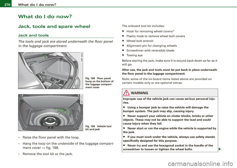
The tools and jack are stored underneath the floor panel
in the luggage compartment.
Raise the floor panel with the loop.
Fig. 188 Floor panel
hung on the bottom of
the luggage compart
ment cover
Fig . 189 Vehicle tool
kit and jack
- Hang the loop on the underside of the luggage compart
ment cover ~ fig. 188.
Remove the tool kit or the jack.
The onboard tool kit includes:
• Hook for removing wheel covers*
• Plasti c hook to remove wheel bolt covers
• Wheel bolt wrench
• Alignment pin for changing wheels
• Screwdriver with reversible blade
• Towing eye
Before storing the jack, make sure it is wound back down as far as it
will go.
After use, the jack and tools must be put back in place underneath
the floor panel in the luggage compartment.
Note: some of the on-board items listed above are provided on
certain models only or are optional extras.
& WARNING
Improper use of the vehicle jack can cause serious personal inju
ries.
• Using a bumper jack to raise the vehicle will damage the
bumper system. The jack may slip, causing injury.
• Never support your vehicle on cinder blocks, bricks or other
objects. These may not be able to support the load and could
cause injury when they fail.
• Never start or run the engine while the vehicle is supported by
the jack.
• If you must work under the vehicle, always use safety stands
specifically designed for this purpose.
• Never try and use the hexagonal socket
in the handle of the
screwdriver to loosen or tighten the wheel bolts.
Page 275 of 324
What do I do now? -__________________ __;__:....:....:..:: __ _
•
-All passengers should leave the car and move to a safe
location (for instance, behind the guardrail)~& .
- Apply the
parking brake firmly ~& .
- Move
selector lever to position Pon an automatic trans-
miss ion; put manual transmission in
first gear ~& .
-If you are towing a trailer : unhitch the trailer from your
vehicle.
- Take the
tool and the spare tire~ page 270 out of the
luggage compartment.
& WARNING
You or your passengers could be injured while changing a wheel if
you do not follow these safety precautions:
• If you have a flat tire, move a safe distance off the road. Turn off
the engine, turn the emergency flasher on and use other warning
devices to alert other motorists.
• Make sure that passengers wait
in a safe place away from the
vehicle and well away from the roadway and traffic.
• To help prevent the vehicle from moving suddenly and possibly
slipping off the jack, always fully set the parking brake and block
the wheel diagonally opposite the wheel being changed. When one
front wheel is lifted off the ground, placing the automatic trans
mission in "P" (Park), or engaging a gear in a manual transmission
will
not prevent the vehicle from moving.
• Before you change a wheel, be sure the ground is level and firm.
If necessary, use a sturdy board under the jack.
• After installing the spare wheel, make sure that you remount
the flat tire/wheel in its storage area properly and tighten the
knurled retaining screw securely. •
Changing a wheel
When you change a wheel, follow the sequence described
below step-by-step and exactly in that order.
1. Remove the decorative wheel cover*. For more details
see also
~ page 274, "Decorative wheel covers" or
~ page 275, "Wheels with cap-covered wheel bolts".
2. Loosen the
wheel bolts ~ page 276.
3. Locate the proper mounting point for the jack and align the jack below that point~
page 276.
4. Lift the car with the jack~ page 276.
5. Take the flat wheel off and then put the spare on
~ page 278.
6. Tighten all wheel bolts lightly .
7.
Lower the vehicle with the jack .
8. Use the wheel bolt wrench and
firmly tighten all wheel
bolts
~ page 276.
9. Put the decorative wheel cover* back on.
& WARNING
Always read and head all WARNINGS and information ::} & in
"Raising the vehicle" on
page 276 and ~ page 279. •
After changing a wheel
A wheel change is not complete without the following
actions.
- Store and secure the replaced wheel in the spare wheel
well. .,._
Do-it-yourself service
Page 277 of 324
What do I do now ? -
------------------
Applies to vehicle s: with cap-covered wheel bolts
Wheels with cap-covered wheel bolts
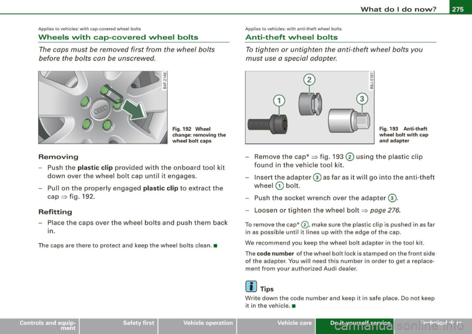
The caps must be removed first from the wheel bolts
before the bolts can be unscrewed.
Removin g
Fig. 19 2 W hee l
c h ange : remov in g th e
whee l bolt ca ps
- Push the plastic clip provided with the onboard tool kit
down over the wheel bolt cap unti l it engages.
- Pull on the properly engaged plastic clip to extract the
cap
~ fig . 192.
R efitting
- Place the caps over the whee l bo lts and p ush them back
1n.
The caps are there to protect and keep the wheel bo lts clean .•
Ap plies to vehicles: with anti-theft wheel bo lts
Anti-theft whee l bolts
To tighten or untighten the anti-theft wheel bolts you
must use a special adapter.
....
(
V"
..
Fi g. 193 Anti-t heft
whee l bolt wit h ca p
a n d ada pter
- Remove the cap*~ fig. 193 0 using the plastic clip
found in the vehicle tool kit.
- Insert the adapter
0 as far as i t wi ll go into the anti-theft
wheel
G) bolt.
- Push the socket wre nch over t he adap ter
0 -
- Loosen or tighten the wheel bolt~ page 276.
To remove the cap* 0, make sure the plastic clip is pushed in as far
in as possib le until it lines up wi th the edge of the cap .
We recommend you keep the wheel bo lt adapter in the tool kit.
The
c od e numb er of the wheel bolt lock is stamped on the front side
of the adap ter. You will need this number in orde r to get a replace
ment from your author ized Audi dealer.
[ i ] Tip s
Write down the code number and keep it in safe place . Do not keep
it in the vehicle. •
Vehicle care Do-it-yourself service Technical data
Page 278 of 324
llffl.,___W_ h_ a _ t_d_ o_ l _d _o_ n_ o_ vv_ ? ______________________________________________ _
Loosening and tightening the wheel bolts
The wheel bolts must be loosened before raising the
vehicle.
~ a'.. ., m
Loosening
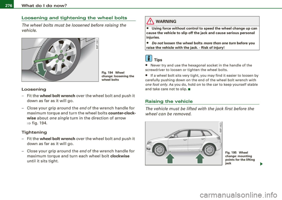
Fig . 194 Wheel
change: loosening the
wheel bolts
-Fit the wheel bolt wrench over the wheel bolt and push it
down as far as it will go .
- Close your grip around the
end of the wrench handle for
maximum torque and turn the wheel bolts
counter-clock
wise
about one single turn in the direction of arrow
~ fig. 194.
Tightening
- Fit the wheel bolt wrench over the wheel bolt and push it
down as far as it will go.
- Close your grip around the
end of the wrench handle for
maximum torque and turn each wheel bolt
clockwise
until it sits tight.
& WARNING
• Using force without control to speed the wheel change up can
cause the vehicle to slip off the jack and cause serious personal
injuries.
• Do not loosen the wheel bolts more than one turn before you
raise the vehicle with the jack. -Risk of injury!
[ i ] Tips
• Never try and use the hexagonal socket in the handle of the
screwdriver to loosen or tighten the wheel bolts.
• If a wheel bolt sits very tight, you may find it easier to loosen by
carefully pushing down on the end of the wheel bolt wrench with
one foot only . As you do, hold on to the car to keep yourself stable
and take care not to slip. •
Raising the vehicle
The vehicle must be lifted with the jack first before the
wheel can be removed.
Fig . 195 Wheel
change: mounting
points
for the lifting
jack ..
Page 280 of 324
11111...__W_ h_ a _ t_d_ o_ l _d _o_ n_ o_ vv_ ? ______________________________________________ _
Taking the wheel off /putt ing the spare on
Follow these instructions step-by-step for changing the
wheel
M
"' ;;; u.
1li
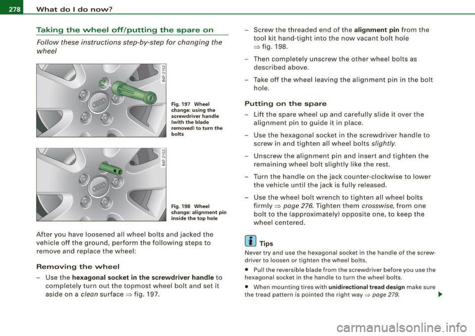
Fig . 197 Wheel
change : using the
screwdriver handle
(with the blade
removed) to turn the
bolts
Fig . 198 Wheel
change: alignment pin
inside the top hole
After you have loosened all wheel bolts and jacked the
vehicle off the ground, perform the following steps to
remove and replace the wheel:
Removing the wheel
- Use the hexagonal socket in the screwdriver handle to
completely turn out the topmost wheel bolt and set it
as ide on a
clean surface ~ fig. 197. - Screw the threaded end of the
alignment pin from the
tool kit hand-tight into the now vacant bolt hole
~ fig. 198.
- Then completely unscrew the other wheel bolts as
described above.
Take off the wheel leaving the alignment pin in the bolt
hole.
Putting on the spare
- Lift the spare wheel up and carefully slide it over the
alignment pin to guide it in place.
- Use the hexagonal socket in the screwdriver handle to
screw in and tighten all wheel bolts
slightly.
Unscrew the alignment pin and insert and tighten the
remaining wheel bolt slightly like the rest.
- Turn the handle on the jack counter -clockwise to lower
the vehicle until the jack is fully released.
- Use the wheel bolt wrench to tighten all wheel bolts firmly ~
page 276. Tighten them crosswise , from one
bolt to the (approximately) opposite one, to keep the
wheel centered.
[ i ] Tips
Never try and use the hexagonal socket in the handle of the screw
driver to loosen or tighten the wheel bolts.
• Pull the reversible blade from the screwdriver before you use the
hexagonal socket in the handle to turn the wheel bolts.
• When mounting tires with
unidirectional tread design make sure
the tread pattern is pointed the right way=>
page 279. ~
Page 284 of 324
11111.___F_ u_ s _ e_s _ a_n _ d_ b_ u_lb _ s _______________________________________________ _
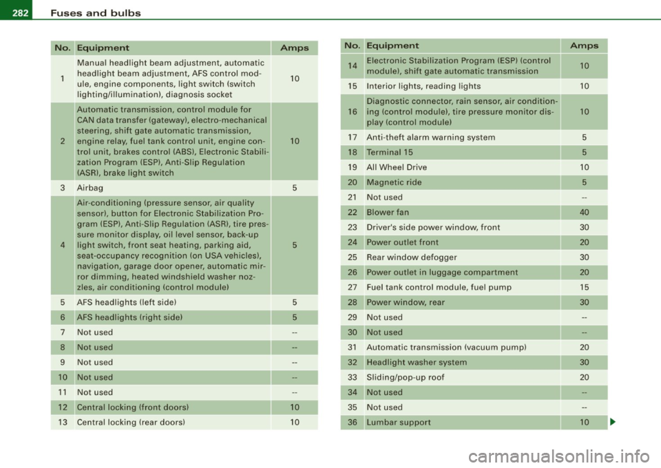
Equipment Amps No. Equipment Amps
Manual headlight beam adjustment, automatic 14 Electronic Stabilization Program (ESP) (control
10
1 headlight beam adjustment, AFS control mod-
10 module),
shift gate automatic transmission
ule, engine components, light switch (switch
15 Interior lights, reading lights 10
lighting/illumination), diagnosis socket
Diagnostic connector, rain sensor, a ir condit ion-
!! Automatic transmission, control module for
16 ing (control module), tire pressure monitor dis- 10
CAN data transfer (gateway), electro -mechanical
play (control module)
steering, shift gate automatic transmission, 17 Anti-theft alarm warning system 5
2 engine relay, fuel tank control unit, engine con
-10
trol unit, brakes control (ABS), Electronic Stabili- 18 Terminal 15
5
zation Program (ESP), Anti -Slip Regulation
19 All Wheel Drive
10
(ASR), brake light switch
-20 Magnetic ride 5
3 Airbag
5
-21 Not used
Air -conditioning (pressure sensor, air quality
sensor), button for Electronic Stabilization Pro- 22
Blower fan 40
gram (ESP), Anti -Slip Regulat ion (ASRl, tire pres -
23 Driver's side power window, front 30
sure mon itor display, oil level sensor, back-up
4 light switch, front seat heating, parking aid, 5 24 Power outlet front
20
seat-occupancy recognition (on USA vehicles), 25 Rear window defogger 30
navigation, garage door opener, automatic mir- 26 Power outlet in luggage compartment 20
ror dimming, heated windshield washer noz-
zles, air conditioning (control module) 27 Fuel tank control module, fuel pump 15
5 AFS headlights (left side)
5 28 Power
window, rear
30
6 AFS headlights (r ight side) 5 29 Not used
7 Not used 30 Not used
8 Not used 31 Automatic transmission (vacuum pump)
20
9 Not used 32 Headlight washer system 30
10 Not used
33 Sliding/pop-up roof
20
1 1 Not used 34 Not used
12 Central locking (front doors} 10 35 Not used
13 Central locking (rear doors) 10
36 Lumbar
support 10
Page 285 of 324
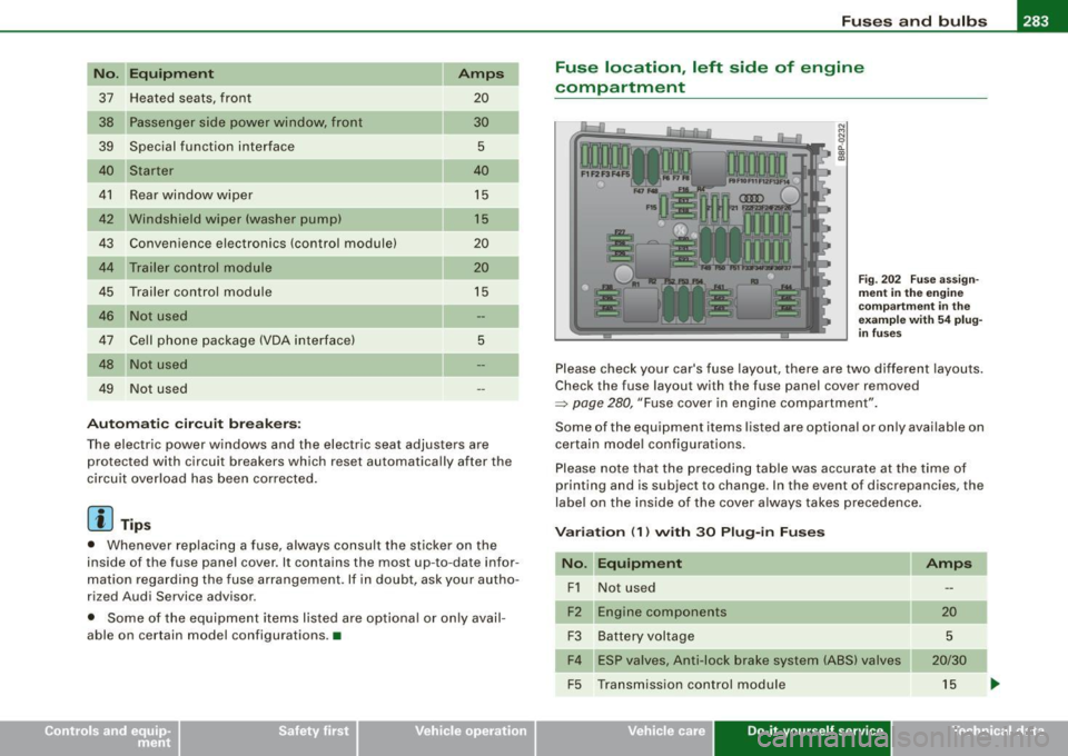
_________________________________________________ F_ u_ s_ e_s _ a_n _d_ b_ u _ lb_ s _ __.ffllll
No . Equipm ent
37 Heated seats, front
38 Passe nger s ide power window, front
39 Special function interface
Starter
41 Rear window wiper
42 Windshield wiper (washer pump)
43 Convenience electronics (control module)
44 Trailer control module
45 Trailer control module
Not used
47 Cell phone package (VOA interface)
48 Not used
49 Not used
Au tom atic cir cuit br eake rs: Amps
20
30
5
40
15
15
20
20
15
5
The electric power windows and the electric seat adjusters are protected with circuit breakers which reset automatically after the
circu it overload has been corrected.
[ i J Tip s
• Whenever replacing a fuse, always consult the sticker on the
inside of the fuse panel cover. It contains the most up-to-date infor
mation regarding the fuse arrangement. If in doubt, ask your autho
rized Audi Service advisor.
• Some of the equipment items listed are optiona l or on ly avail
able on certain model configurations. •
Fuse location , left side of engine
compartment
N M N
~ (X) 0)
Fig . 202 F use ass ign
m ent in th e e ngin e
co mpar tment in th e
e xampl e wit h
54 p lu g
in fu ses
Please check your car's fuse layout, there are two different layouts.
Check the fuse layout with the fuse panel cover removed
~ page 280, "Fuse cover in engine compartment" .
Some of the equipment items listed are optional or on ly available on
certain model configurations.
Please note that the preceding table was accurate at the time of
printing and is subject to change . In the event of discrepancies, the
label on the inside of the cover a lways takes precedence.
V ariation (1 ) with 30 Plu g-in F uses
No . Equipm ent
F1 Not used
Engine components
F3 Battery voltage
F4 ESP v alves, Anti -lock brake system (ABS) valves
F5 Transmission control module
Vehicle care Do-it-yourself service
Amps
20
5
20/30
15
Technical data
Page 286 of 324

IIJII Fuses and bulbs i,.__....;,___;:,,;_,;,,.:_;__;;:_.:.:..:..=-=;____ ______________________ _
No. UEquipment Amps I No. Equipment Amps
F6 Steering wheel electronics, instrument cluster
5 F28
Not used
F7 Transmission control module 30 Fuse assignment in the left-side instrument
F29 50
F8 Navigation system, radio system 15/25 panel (special equipment)
Navigation system, digital radio, cell phone, TV F30 Power supply relay terminal
15 50
F9 equipment 5
F10 Engine control module, main relay 5/10 Variation
(2) with 54 Plug-in Fuses
F11 Not used No. Equipment
Amps
Control module for CAN data transfer (gateway) 5 F1
Vehicle
electrical system control unit (right)
30
F13 Engine control module 15/25 F2
ESP valves, Anti
-lock brake system (ABS) valves
20/30
F14 Ignition coils 20 F3 Not used
F15 Tank diagnosis, oxygen sensor 5/10 F4
Battery voltage
5
F16 Vehicle electrical system control unit (right) 30 F5 Horn
15
F17 Horn
15 F6 Engine components, fuel pump 15
F18 Audio amplifier 30 F7
Not used
F19 Front windshield wiper system 30 F8
Not used
F20 Water return
-flow pump, volume regulator valve F9 Engine components
10
F21 Oxygen sensor, vacuum pump 15 F10
Fuel tank control, mass air flow sensor
10
F22 Clutch pedal switch, brake light switch 5 F11 Oxygen sensors, in front of catalytic converter 10
F23 Engine relays, engine components
5/10/15 F12 Oxygen sensors, behind catalytic converter
10
F24 Engine components, water return-flow pump 10 F13 Automatic transmission
15
F25 Pump (ESP/ABS), ABS valve 30/40 F14 Not used
F26 Vehicle electrical system control unit (left)
30 F15 Water return-flow pump
10
F27 Secondary air pump 40 F16 Volume control valve
20
F17 Steering wheel electronics, instrument cluster
5
F18 Audio amplifier 30
F19 Navigation system, radio system 15/25