AUDI S3 2010 Owner's Manual
Manufacturer: AUDI, Model Year: 2010, Model line: S3, Model: AUDI S3 2010Pages: 320, PDF Size: 75.34 MB
Page 21 of 320
& WARNING (continued)
• Always remember, even if the "snowflake" symbol (ice
warning) does not appear in the display, black ice could be on the
road.
• Always reduce your speed and drive with special care in cold
weather conditions when the chance of encountering icy road
surfaces increases.
[ i] Tips
• If the vehicle is stationary , or if you are driving at a very low
speed, the temperature shown in the display might be slightly
higher than the actual outside temperature. This is caused by the
heat being radiated from the engine.
• On vehicles with S tronic, the reminders do not appear in the
display until you select a gear .
• On vehicles with Audi Navigatio n system*, the displays may
differ from their normal appearance during navigation. •
Applies to ve hicles: with g ears hift indicator and manual transmi ssio n
Gearshift recommendation
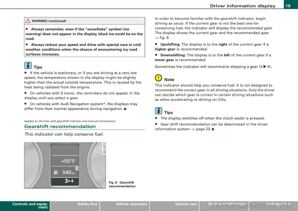
This indicator can help conserve fuel.
Controls and equip
ment
+55°F
~ 340mi
3~4 Fig . 8 Gearshift
recommendation
Driver information display
In order to become familiar with the gearshift indicator, begin
driving as usual. If the current gear is not the best one for
conserving fuel, the indicator will display the recommended gear .
The display shows the current gear and the recommended gear
=> fig. 8 .
• Upshifting: The display is to the right of the current gear if a
higher gear is recommended.
• Downshifting: The display is to the left of the current gear if a
lower gear is recommended.
Sometimes the indicator will recommend skipping a gear (3.,. 5l.
0 Note
This indicator should help you conserve fuel. It is not designed to
recommend the correct gear in all driving situations. Only the driver
can decide which gear is correct in cer tain driving situations such
as when accelerating or driving on hills.
[ i] Tips
• The display switches off when the clutch pedal is pressed.
• Gear shift recommendation can be deactivated in the driver
information system
=> page 23. •
I • •
Page 22 of 320
Driver information display
Service interval display
The service interval display reminds you when your next
service is due.
Fig. 9 Section of
instrument cluster:
Service interval display
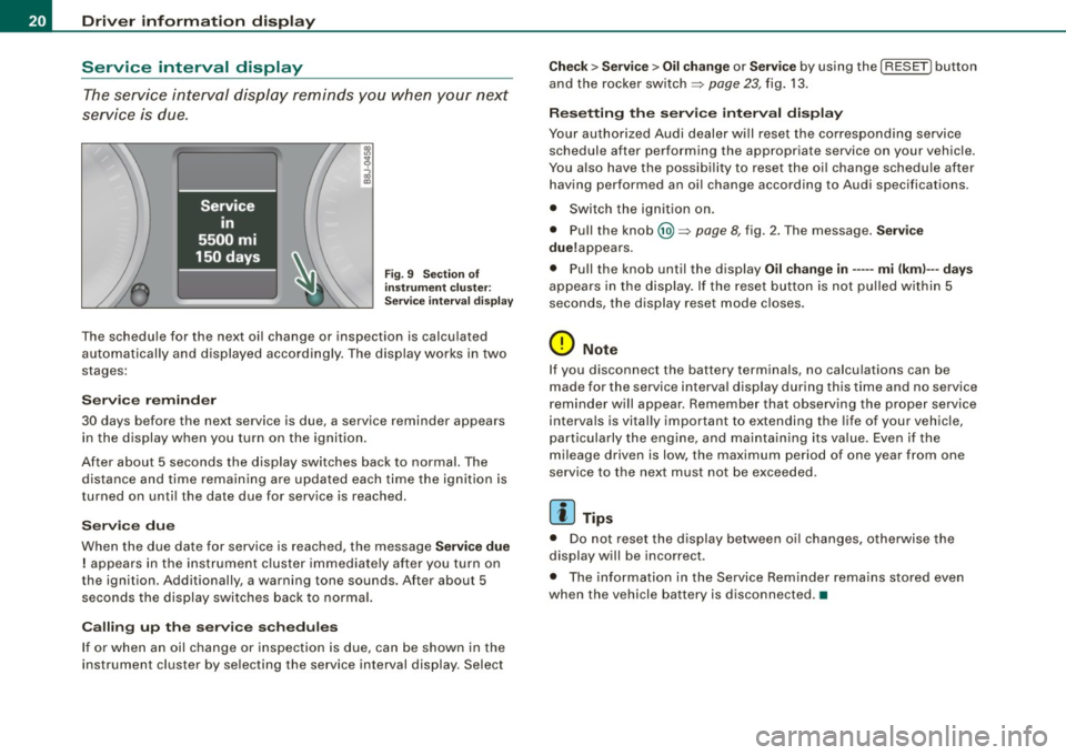
The schedule for the next oil change or inspection is calculated
automatically and displayed accordingly. The display works in two
stages:
Service reminder
30 days before the next service is due, a service reminder appears in the display when you turn on the ignition.
After about 5 seconds the display switches back to normal. The distance and time remaining are updated each time the ignition is
turned on until the date due for service is reached.
Service due
When the due date for service is reached, the message Service due
! appears in the instrument cluster immediately after you turn on
the ignition. Additionally, a warning tone sounds. After about 5 seconds the display switches back to normal.
Calling up the service schedules
If or when an oil change or inspection is due, can be shown in the
instrument cluster by selecting the service interval display . Select
Check > Service > Oil change or Service by using the [ RESET! button
and the rocker switch =>
page 23, fig. 13.
Resetting the service interval display
Your authorized Audi dealer will reset the corresponding service
schedule after performing the appropriate service on your vehicle.
You also have the possibility to reset the oil change schedule after
having performed an oil change according to Audi specifications.
• Switch the ignition on.
• Pull the knob @=>
page 8, fig. 2. The message. Service
due!appears .
• Pull the knob until the display
Oil change in----- mi (kml---days
appears in the display . If the reset button is not pulled within 5
seconds, the display reset mode closes .
0 Note
If you disconnect the battery terminals, no calculations can be
made for the service interval display during this time and no service
reminder will appear. Remember that observing the proper service
intervals is vitally important to extending the life of your vehicle,
particularly the engine, and maintaining its value. Even if the
mileage driven is low, the maximum period of one year from one
service to the next must not be exceeded.
[ i] Tips
• Do not reset the display between oil changes, otherwise the
display will be incorrect.
• The information in the Service Reminder remains stored even
when the vehicle battery is disconnected .•
Page 23 of 320
On-Board Diagnostic system (08D)
On-Board Diagnostics
Fig. 10 location of
Data Link Connecto r
( DL C)
On-Board Diagnostics monitors the components of your emission
control system . Each controlled component in your engine system
has been assigned a code. In case of a malfunction , the component
will be identified and the fault stored as a code in the control
module memory .
The Mil lamp may also illuminate if there is a leak in the on-board
fuel vapor recovery system . If the light illuminates after a refuelling,
pull off the road and stop the vehicle, then check that the fuel filler
cap is properly closed
=> page 220 .
In order to make an accurate diagnosis, the stored data can only be
displayed using special diagnostic equipment (generic scan tool for
OBDl.
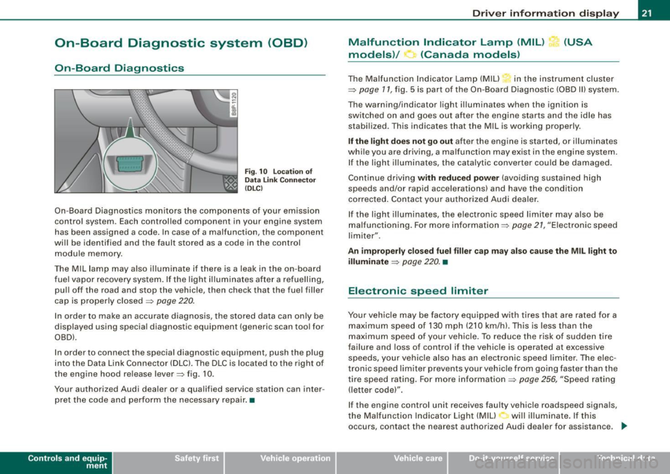
In order to connect the special diagnostic equipment, push the plug
into the Data Link Connector (DLC). The DLC is located to the right of
the engine hood re lease lever=> fig. 10.
Your authorized Audi dealer or a qualified service station can inter
pret the code and perform the necessary repair. •
Contro ls and eq uip
ment
Driver information display
Malfunction Indicator Lamp (MIL) (USA
models)/ (Canada models)
The Malfunction Indicator Lamp (MIU in the instrument cluster
=> page 11, fig . 5 is part of the On-Board Diagnostic (OBD II) system .
The warning/indicator light illuminates when the ignition is
switched on and goes out after the engine starts and the idle has
stabilized. This indicates that the Mil is working properly .
If the light does not go out after the engine is started, or illuminates
while you are driving, a ma lfunction may exist in the engine system.
If the light illuminates, the catalytic converter could be damaged.
Continue driving
with reduced power (avoiding sustained high
speeds and/or rapid accelerations) and have the condition
corrected . Contact your authorized Audi dealer.
If the light illuminates , the electronic speed limiter may also be
malfunctioning. For more information=>
page 21, "Electronic speed
limiter".
An improperly closed fuel filler cap may also cause the MIL light to
illuminate
=> page 220. •
Electronic speed limiter
Your vehicle may be factory equipped with tires that are rated for a
maximum speed of 130 mph (210 km/h) . This is less than the
maximum speed of your vehicle. To reduce the risk of sudden tire
failure and loss of control if the vehicle is operated at excessive
speeds, yo ur vehicle also has an electronic speed limiter. The elec
tronic speed limiter prevents your vehicle from going faster than the
tire speed rating. For more information
=> page 256, "Speed rating
(letter code)".
If the engine control unit receives faulty vehicle roadspeed signals,
the Malfun cti on Indicator Light (MIU will illuminate . If this
occurs, contact the nearest authori zed Audi dealer for assistance. _.,
Vehicle care I I irechnical data
Page 24 of 320
Driver information display
& WARNING
Always observe the posted speed limits and adjust your speed to
suit prevailing road, traffic and weather conditions. Never drive
your vehicle faster than the maximum speed rating of the tires
installed. •
Trip computer
Introduction
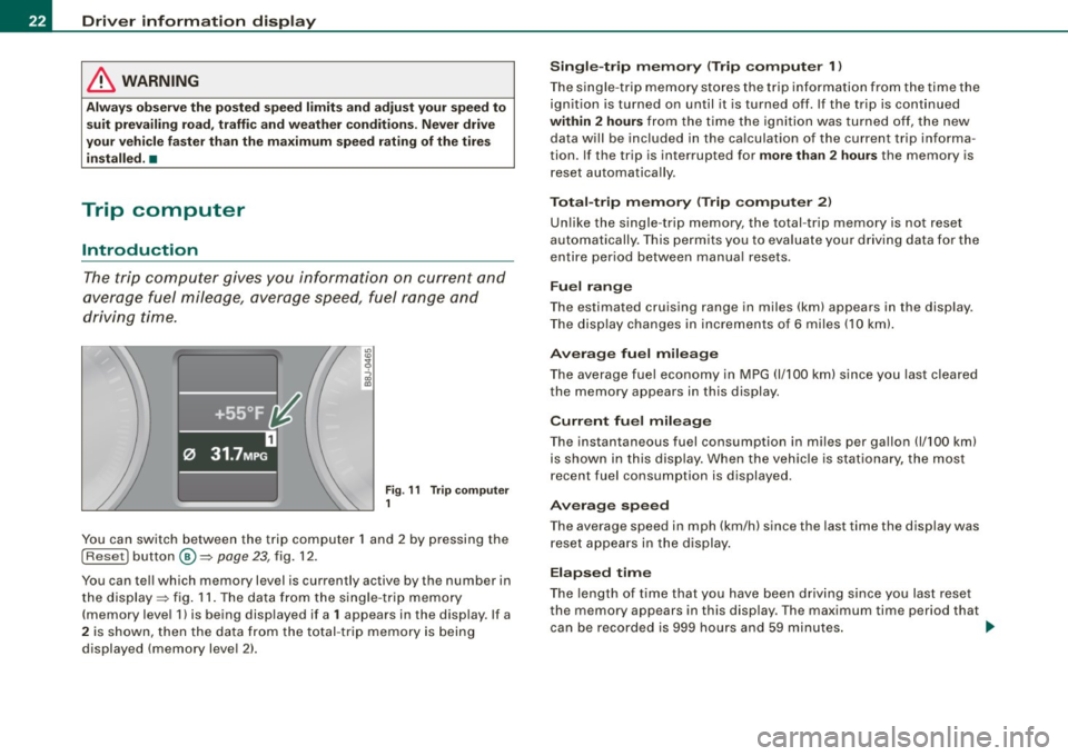
The trip computer gives you information on current and
average fuel mileage, average speed, fuel range and
driving time.
Fig . 11 Trip computer
1
You can switch between the trip computer 1 and 2 by pressing the
I Reset I button @=> page 23, fig. 12.
You can tell which memory level is curren tly active by the number in
the display => fig. 11. The data from the single -trip memory
(memory level 1) is being displayed if a
1 appears in the display . If a
2 is shown, then the data from the total -trip memory is being
displayed (memory level 2).
Single-trip memory (Trip computer 1)
The single -trip memory stores the trip information from the time the
ignition is turned on until it is turned off. If the trip is continued
within 2 hours from the time the ignition was turned off, the new
data will be included in the calculation of the current trip informa
tion. If the trip is interrupted for
more than 2 hours the memory is
reset automatically.
Total-trip memory (Trip computer 2)
Unlike the single-trip memory, the total-trip memory is not reset
automatically. This permits you to evaluate your driving data for the
entire period between manual resets.
Fuel range
The estimated cruising range in miles (km) appears in the display .
The display changes in increments of 6 miles (10 km).
Average fuel mileage
The average fuel economy in MPG 0/100 km) since you last cleared
the memory appears in this display.
Current fuel mileage
The instantaneous fuel consumption in miles per gallon 0/100 km)
is shown in this display. When the vehicle is stationary, the most
recent fuel consumption is displayed.
Average speed
The average speed in mph (km/h) since the last time the display was
reset appears in the display.
Elapsed time
The length of time that you have been driving since you last reset
the memory appears in this display . The maximum time period that
can be recorded is 999 hours and 59 minutes.
~
Page 25 of 320
Distance
The elapsed distance since the last time the memory was cleared
appears in the display. The maximum distance that can be recorded
is 9,999 .9 miles (9,999.9 kilometers).
[ i ) Tips
All stored values will be lost if the vehicle battery is disconnected. •
Operation
The trip computer is controlled by two switches on the
windshield wiper lever.
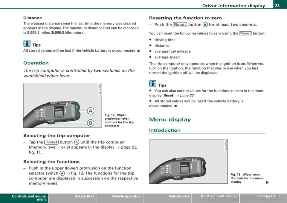
Selecting the trip computer
Fig. 12 Wiper
arm/wiper lever:
co ntr ols for the trip
co mputer
- Tap the [Reset) button © until the tr ip computer
(memory level 1 or 2) appears in the display =>
page 22,
fig. 11.
Selecting the functions
- Push in the upper (lower) protrusion on the functi on
se lector switch @=>fig . 12. The functions for the trip
computer are displayed in succession on the respective
memory levels.
Contro ls and eq uip
ment
Driver information display
Resetting the function to zero
- Push the
(Reset] button © for at least two seconds.
You can reset the following values to zero using the [Reset] button:
• driving time
• distance
• average fue l mi leage
• average speed
The trip computer only operates when the ignition is on. When you
turn on the ignition, the function that was in use when you last
tu rned the ignition off will be displayed.
[ i ) Tips
• You can also set the values for the functions to zero in the menu
display
( Reset) ~ page 23.
• All stored values will be lost if the vehicle battery is
disconnected .•
Menu display
Introduction
Fig . 13 Wiper lever:
Controls for the menu
di sp la y ..,
Vehicle care I I irechnical data
Page 26 of 320
Driver informati on displ ay
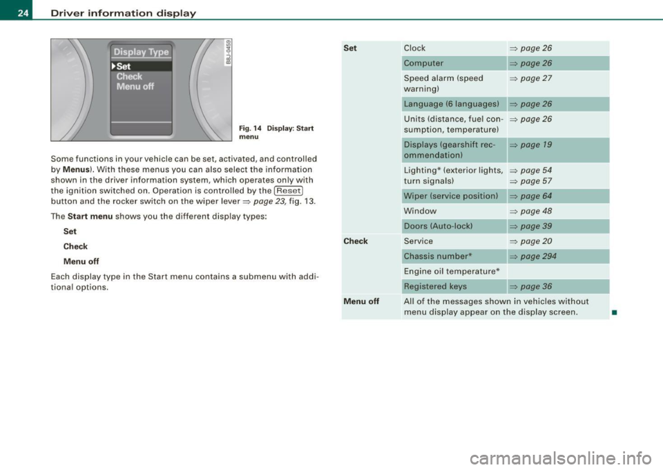
Fig. 1 4 Display : Start
menu
Some func tions in your vehicle can be se t, act iva ted, and cont rolled
by
M enu s). With these menus you can also select the information
shown in the driver information system , which ope rates only with
the ignition switched on. Operation is controlled by the
! R ese t]
button and the rocker switch on the wiper lever=> page 23, fig. 13 .
The
S ta rt m enu shows you the diff erent disp lay types :
Set
C hec k
M enu off
Each display type in the Start menu con tains a submenu with addi
tional options.
Se t
C hec k
M enu off Clock
=> page 26
Computer => page26
Speed alarm (speed => page27
warning)
Language (6 languages)
Units (distance, fuel con- =>
page26
sumption, temperature)
Displays (gearshift rec -
=> page 19
ommendation)
Lighting * (exterior lights,
=>
page 54
turn signals) => page 57
Wiper (service position) => page 64
Window => page 48
Doors (Auto-lock)
Service
=>
page20
Chassis number* => page294
Engine oil temperature*
Registered
keys => page 36
All of the messages shown in vehicles without menu disp lay appear on the display screen.
•
Page 27 of 320
Navigating the menu
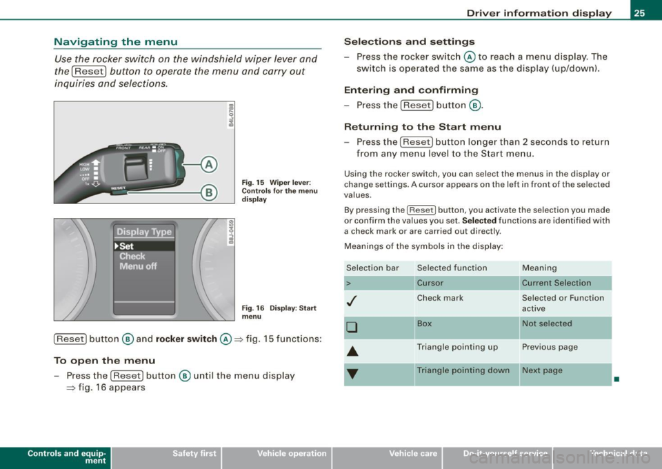
Use the rocker switch on the windshield wiper lever and
the
I Reset I button to operate the menu and carry out
inquiries and selections.
Fig . 15 Wiper lever:
Controls for the menu
display
Fig . 16 Display: Start
menu
[Reset] button @ and rocker switch @~ fig. 15 functions:
To open the menu
- Press the (Reset ] button @ until the menu display
~ fig. 16 appears
Con tro ls and eq uip
ment
Driver information display
Selections and settings
- Press the rocker switch @ to reach a menu display. The
switch is operated the same as the display (up/downl.
Entering and confirming
- Press the (Reset] button @.
Returning to the Start menu
Press the [ Reset] button longer than 2 seconds to return
from any menu level to the Start menu.
Using the rocker switch, you can selec t the menus in the display or
change settings. A cursor appears on the left in front of the selected
values.
By pressing the (Reset] button , you activate the selection you made
or confirm the values you set.
Selected functions are identified with
a check mark or are carried out directly .
Meanings of the symbols in the display:
Selection bar
>
./
D
--
Selected function
Cursor
Check mark Meaning
Current Selection
Selected
or Function
active
Box Not selected
-Triangle pointing up Previous page
Triangle pointing down Next page
•
Vehicle care I I irechnical data
Page 28 of 320
Driver informati on displ ay
Selecting settings
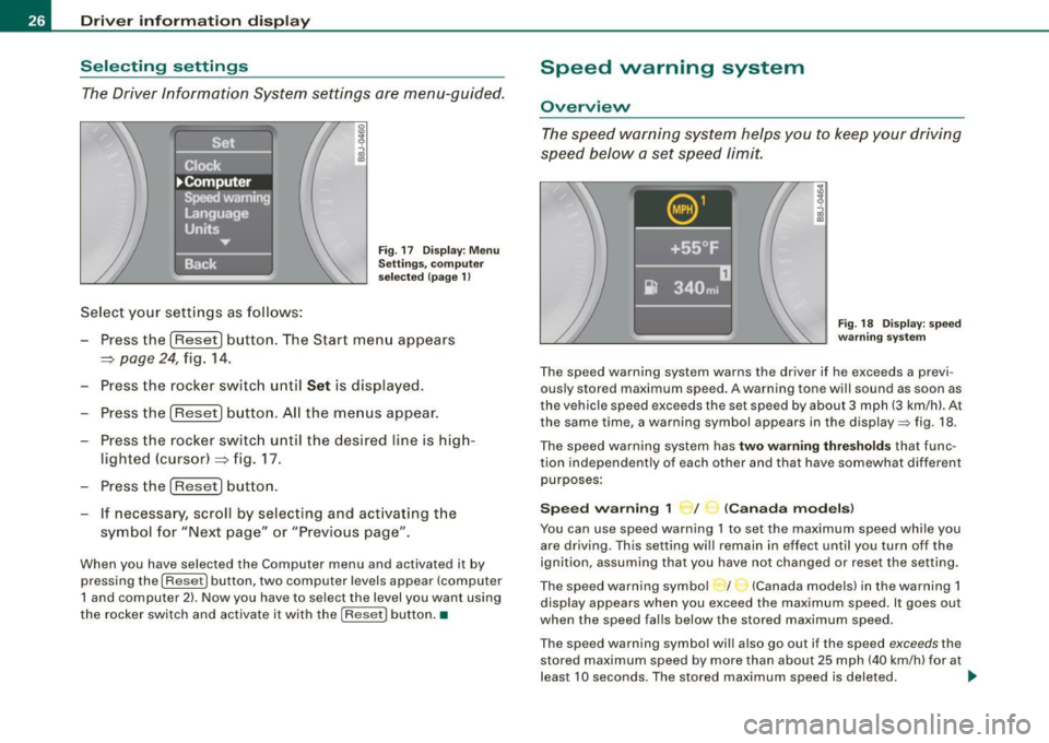
The Driver Information System settings are menu-guided.
Select your settings as follows:
Fig . 17 Dis play: Men u
Sett ings, co mputer
sel ected (page 1)
- Press the !Reset) button. The Start menu appears
~ page 24, fig. 14.
- Press the rocker switch until
Set is displayed.
- Press the
(Reset] button. All the menus appear.
- Press the rocker switc h until the desired line is hig h-
lighted (cursor)~ fig. 17.
- Press the
!Reset] button .
- If necessa ry, scroll by selecting and activating t he
symbol for "Next page" or "Previous page".
When you have selected the Computer menu and activated it by
pressing the
I Reset] button, two computer levels appear (computer
1 and computer 2) . Now you have to select the level you want using
the rocker switch and activate it with the [R ese t] button. •
Speed warning system
Overview
The speed warning system hel ps you to keep your driv ing
speed below a set speed limit.
F ig. 18 Disp lay : sp ee d
w arni ng s yste m
The speed warning system warns the dr iver if he exceeds a previ
ous ly stored maximum speed . A warning tone will sound as soon as
the vehicle speed exceeds the set speed by about 3 mph (3 km/h). At
the same time, a warning symbol appears in the display=> fig. 18.
The speed war ning system has
two warn ing thre shold s that func
tion independently of each other and that have somewhat different
purposes :
Spee d warning 1 ~ / (Canad a mod els)
You can use speed warning 1 to set the maximum speed whi le you
are driving. This setting will remain in effect until you turn off the
ignition, assuming that you have not changed or reset the set ting.
The speed warning symbo l / (Canada models) in the warning 1
display appears when you exceed the maximum speed. It goes out
when the speed falls below the stored maximum speed.
T he speed warning symbol wi ll also go out if the speed
exceeds the
stored maximum speed by more than about 25 mph (40 km/h) for at
leas t 10 seconds . The stored maximum speed is deleted. .,_
Page 29 of 320
Setting speed warning 1 ~ page 27.
Speed warning 2 ,,. / (Canada models)
Storing warning 2 is recommended if you always want to be
reminded of a certain speed, for example when you are traveling in
a country that has a general maximum speed limit, or if you do not
want to exceed a specified speed for winter tires.
The speed warning 2 symbol, /
,J. (Canada models) appears in the
display when you exceed the stored speed limit. Unlike warning 1,
it will not go out until the vehicle speed drops below the stored
speed limit.
Setting speed warning 2
~ page 27.
[ i ] Tips
Even though your vehicle is equipped with a speed warning system,
you should still watch the speedometer to make sure you are not
driving faster than the speed limit. •
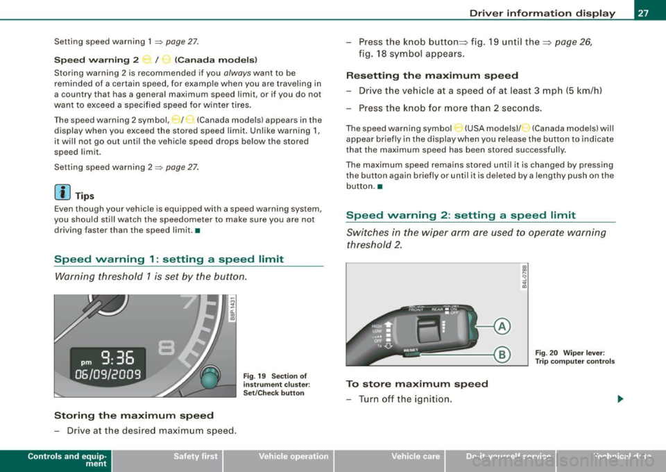
Speed warning 1: setting a speed limit
Warning threshold 1 is set by the button.
Storing the maximum speed
-Drive at the desired maximum speed .
Contro ls and eq uip
ment
Fig . 19 Section of
instrument cluster:
Set/Check button
Driver information display
- Press the knob button~ fig. 19 until the~ page 26,
fig. 18 symbol appears.
Resetting the maximum speed
- Drive the vehicle at a speed of at least 3 mph (5 km/h)
- Press the knob for more than 2 seconds.
The speed warning symbol·-(USA models) /- (Canada models) will
appear briefly in the display when you release the button to indicate
that the maximum speed has been stored successfully.
The maximum speed remains stored until it is changed by pressing
the button again briefly or until it is deleted by a lengthy push on the
button. •
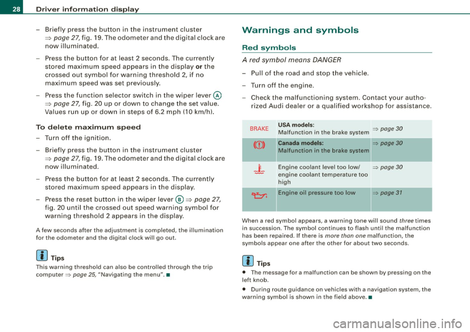
Speed warning 2: setting a speed limit
Switches in the wiper arm are used to operate warning
threshold 2.
To store maximum speed
- Turn off the ignition.
Vehicle care I I
Fig. 20 Wiper lever:
Trip computer controls
irechnical data
Page 30 of 320
Driver inf ormati on displ ay
- Briefly press the button in t he ins trument cluster
=>
page 27, fig . 19. T he odome ter and the digita l clock are
now illuminated .
- Press the button for at least
2 seconds. The currently
stored maximum speed appears in the display
or the
crossed out symbol for warning threshold
2, if no
maximum speed was set previously .
- Press the function selector switch in the wiper lever @
=>
page 27, fig. 20 up or down to change t he set value .
Values r un up or dow n in steps of
6.2 mph (10 km/h) .
To dele te max imum sp eed
-Turn off the ignition.
- Briefly press the button in t he instrument cluster
=>
page 27, fig . 19. The odometer and the digita l clock are
now illuminated.
- Press the butt on for at least 2 seconds. T he currently
stored maximum speed appears in the display.
- Press the rese t button in the wiper lever @=>
page 27,
fig. 20 unt il the crossed out speed warning symbo l for
warning threshold 2 appears in the display.
A few seconds after the adjustment is comp leted, the i llumination
for the odometer and the digital clock wil l go out .
[ i ] Tip s
This warning threshold can also be controlled through the trip
computer =>
page 25, "Navigating the menu". •
Warnings and symbols
Red symbols
A red symbol means DANGER
-Pull of the r oad and stop t he vehicle .
- Turn o ff the engine .
Check the malfunctioning system. Contact your autho
rized Audi dealer or a qua lified workshop for assistance .
BRAKE USA m odels: => page 30 Ma lfunction in the brake system
CCD > Ca na da m odel s: => page 30
Malfunction in the brake system
_t_ Engine coolant level too low/ => page 30
-engine coolant temperature too
high
~ Engine oil pressure too low => page 37
- --
When a red symbol appears, a warning tone will sound three times
in succession. The symbol continues to flash unti l the malfunction
has been repaired . If there is
more than one malfunction, the
symbols appear one after the other for about two seconds.
[ i ] Tip s
• The message for a malfunction can be shown by pressing on the
left knob.
• During route guidance on vehicles with a navigation system, the
warn ing symbo l is shown in the field above .•