instrument cluster AUDI S3 2010 Owners Manual
[x] Cancel search | Manufacturer: AUDI, Model Year: 2010, Model line: S3, Model: AUDI S3 2010Pages: 320, PDF Size: 75.34 MB
Page 9 of 320
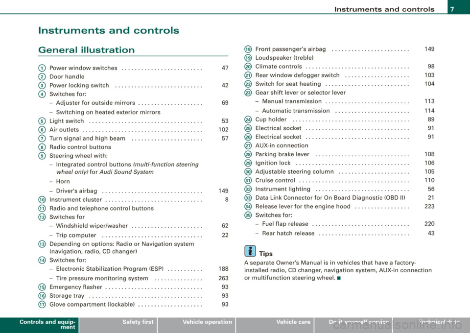
Instruments and controls
General illustration
G)
0
©
©
Power window switches
Door handle
Power locking switch
Switches for:
- Adjuster for outside mirrors .. ........ ... ...... .
- Switching on heated exterior mirrors
© Light switch .................................. .
© Air outlets .... .... ... .. ............... ........ .
0 Turn signa l and high beam ...... ............. .. .
@ Radio control buttons
@ Steering wheel with:
-Integra ted control buttons (multi -function steering
wheel only) for Audi Sound System
-Horn
- Driver's airbag .............................. .
@ Instrument cluster .................... ...... ... .
@ Radio and telephone control buttons
@ Switches for
- Windshield wiper/washer .... ... .. ...... ... ... .
- Trip computer .... ................... ....... .
@ Depending on options: Radio or Navigation system
(navigation, radio, CD changer)
@ Switches for:
- Electronic Stabilization Program (ESP) .......... .
- Tire pressure monitoring system .. ... .. .... ... .
@ Emergency flasher ............................. .
@) Storage tray .. ... .... ... ... ... .. .. .... ........ .
@ G love compartment ( lockab le) ..... ........ .... .. .
Controls and equip
ment
47
42
69
53
102
57
149
8
62
22
188
263 93
93
93
Instruments and controls
@
@
@
@
@
@
Front passenger's airbag
Loudspeaker (treble)
Climate controls .. ..... .. ..... ........... ...... .
Rear window defogger switch ...... ............ . .
Switch for seat heating .. ...... .... .... ......... .
Gear shift lever or selector lever
M I .. - anua transm1ss1on . ........... ....... .... .. .
- Automatic transmission ... ... ...... .... .... .. .
Cup holder ...... ...... ....... ...... .......... .
Electrical socket ............................... .
Elect rical socket ............................... .
AUX-in connection
Parking brake lever ............................ .
Ignition lock ........ ................ .... ...... .
Adjustable steering column ...... .... .... ..... .. .
Cruise control .. ........ ....... ...... .... ...... .
Instrument lighting ............................ .
Data Link Connector for On Board Diagnostic (OBD Ill
Release lever for the engine hood
Switches for:
- Fuel flap release .......... ...... .... ......... .
- Rear hatch release
[ i ] Tips
149
98
103
104
113
114
89
91
91
108
106
105
110 56
21
223
220
43
A separate Owner's Manual is in vehic les that have a factory
insta lled radio, CD changer, navigation system, AUX -in connection
or multifunction steering wheel. •
I • •
Page 10 of 320
Instruments and warning/indicator lights
Instruments and warning/indicator lights
Instruments
Instrument cluster and controls
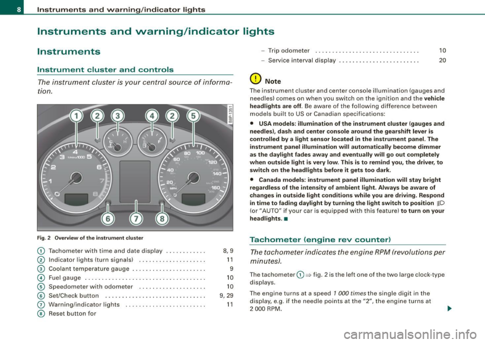
The ins trum ent cluster is your central source of informa
ti on.
Fig . 2 Overv ie w of th e instrume nt clu ster
0
0
0
©
©
©
G)
©
T achometer with time and date display ......•.....
I ndicator lights (turn signals) ... ....... .... ..... .
Coo lant temperature gaug e .... ... ...... ...... .. .
Fuel gauge .. ... .... .. ...... .... ... ..... ... ... .
S pe edom eter wi th o do met er ..... .... ... .. .. ... .
Se t/Chec k button ..... ... ..... ..... ... ........ .
Warn ing/indicator l ights
Reset but ton for 8,9
1 1
9
1 0
1 0
9 , 29
1 1
- Trip odomete r 10
-Service i nterv al dis play . . . . . . . . . . . . . . . . . . . . . . . . 20
(D Note
The instrument clu ste r and center c onsole i lluminati on (gauge s and
n eedles) comes on w hen you sw itch on the ignit ion and the vehicle
he adl ights are off . Be awa re of the following difference betw een
models built to US or Canad ian specificat io ns:
• USA models : illumination of the instrument cluster (gauges and
needles), dash and center con sole around the gear shift lever is
controlled by a light sensor located in the instrument panel. The
instrument panel illumination will automatically become dimmer
as the daylight fades away and eventually will go out completely
when outside light is very low . This is to remind you, the driver , to
sw itch on the headlights befo re it gets too dark .
• Canada models: instrument panel illumination will stay bright
regardless of the intensit y of ambient light . Always be aware of
changes in outside light conditions while you are driving . Respond
in time to fading dayl ight by turning the light swit ch to position
jD
(or" AUTO" if you r car i s equi ppe d with this feature) to turn on your
headlights . •
Tachometer (engine rev counter)
T h e ta chom eter ind icates the e ngine RPM (revo luti ons pe r
minut es).
The tachom eter 0 => fig . 2 is the left on e of the two large clock -type
dis plays .
The engine turns at a speed 1 000
times the single di git in the
display, e.g . if the needle p oints at the "2", the eng ine t urns at
2 000 RP M.
Page 11 of 320

If the engine RPMs drop below 1 500, you should downshift to the
next lower gear. The red area at the end of the scale indicates
maximum permissible engine RPMs after the break-in period.
Before reaching this area, you should either shift into the next
higher gear or ease your foot off the accelerator pedal .
0 Note
The tachometer needle=> page 8, fig. 2 G) should not move into the
red range. If it does, then only for a very short period of time. You
could damage your engine by driving at high RPM!
<£> For the sake of the environment
Upshifting early saves fuels and reduces engine noise. •
Digital clock with date display
Your vehicle is equipped with a quartz controlled digital
clock.
To set the hour
Fig . 3 Instrument
cluster with: the digital
clock and date
-Pull the knob (hour display flashes) and turn it to the left
or rig ht.
Con tro ls and eq uip
ment
Instruments and warning/indicator lights
To set the minutes
- Pull the button until the minute display flashes.
- Turn the knob to the left or right until the desired setting
appears.
To set the time format (12 or 24-hour display)
- Pull the knob until the time format display flashes.
- Turn the knob to the left or right.
To set the date
-Pull the knob until the day, month or year display flashes.
- Turn the knob to the left or right.
To show or hide the date display
-Pull the knob until the date display flashes.
- Turn the knob to the left or right.
When the date display stops flashing, this means the time and date
have been successfully stored.
With the ignition off, pushing or pulling the Set/Check button
=>
page 8, fig . 2 © -depending on the instrument cluster configu
ration -can turn on the display field lighting for a few seconds. •
Engine coolant temperature gauge
The engine coolant gauge 0 => page 8, fig. 2 only works when the
ignition is on. To prevent damage to your engine, please note the
following important points:
~
Vehicle care I I irechnical data
Page 12 of 320
Instruments and warning/indicator lights
Engine cold
As long as the needle remains at the left end of the gauge, the
engine still has not reached its operating temperature . Avoid high
engine speeds, heavy engine loads and heavy throttle.
Normal temperature
When the engine has reached its operating temperature, the needle
will move into the middle of the gauge and remain there. If the engine is working hard at high outside temperatures, the needle
may turn further to the right. This is no cause for concern as long as
the
_ f_ warning light in the instrument cluster does not illuminate.
When the
-L warning light starts to flash, this can mean one of two
things: either the coolant
temperature is too high, or the coolant
level is too low=> page 30.
& WARNING
• Always observe the warning in=> page 215, "Engine compart
ment" before opening the engine hood and checking the engine
coolant level.
• Never open the engine hood if you see or hear steam, or if you
see engine coolant dripping from the engine compartment. You
could burn yourself. Let the engine cool off first so that you cannot
hear or see any steam or engine coolant.
0 Note
• Mounting additional lights or accessories in front of the air inlets
reduces the cooling effect of the radiator . At high outside tempera
tures or high engine load, the engine could overheat.
• The front spoiler has been designed to properly distribute the
cooling air when the vehicle is moving. If the spoiler is damaged,
this could reduce the cooling effect and the engine could then over
heat. Ask your authorized Audi dealer for assistance. •
Fuel gauge
The fuel gauge works only when the ignition is on.
When the needle reaches the red area, the warning light in the
instrument cluster will illuminate=>
page 32 I). This means you
have approximately 1.8 gallons (7 liters) of fuel left in the tank.
Time
to refuel!
The total tank capacity of your vehicle is listed in=> page 296,
"Data".
0 Note
Never run the tank completely dry! An irregular supply of fuel can
cause engine misfiring and fuel could enter into the exhaust
system. The catalytic converter could then overheat and be
damaged .•
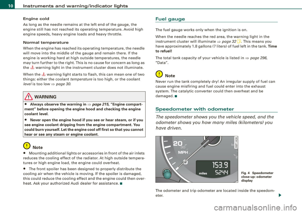
Speedometer with odometer
The speedometer shows you the vehicle speed, and the
odometer shows you how many miles (kilometers) you
have driven.
Fig. 4 Speedometer
close-up : odometer
display
The odometer and trip odometer are located inside the speedom
eter.
Page 13 of 320
• USA models -Miles
• Canadian models -Kilometers
Lower odometer
The lower odometer shows the total number of miles (kilometers)
driven .
Upper odometer (trip odometer)
The upper odometer shows the total number of miles (kilometers)
driven since you last reset the odometer back to zero . You can use
this odometer when you want to keep track of how many miles (kilo
meters) you have driven for a single trip or errand. The last digit indi
cates 1/10 of a mile (100 metres). You can set the trip odometer back
to zero by pressing the reset button::::,
page 10, fig. 4.
Malfunction message
If there is a malfunction somewhere in the instrument cluster, dEF
will appear in the trip odometer and will stay on. Contact your
authorized Audi dealer to have the problem corrected.
Immobilizer
When the ignition is switched on , the data on the ignition key are
scanned automatically.
If an unauthorized key was used,
SAFE is displayed continuously in
the odometer display field . The vehicle cannot be operated
=>
page 38.
[ i J Tips
• The digital clock and the odometer are turned on for about 30
seconds when the driver's door is opened .
• When the ignition is turned off, the odometer reading and the
digital clock with date display can be switched on for about
30 seconds by pressing the knob::::, page 8, fig. 2 @. •
Con tro ls and eq uip
ment
Instruments and warning/indicator lights
Warning /indicator lights
Overview
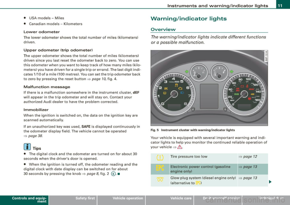
The warning/indicator lights indicate different functions
or a possible malfunction.
Fig. 5 Instrument cluster with warning/indicator lights
Your vehicle is equipped with several important warning and indi
cator lights to help you monitor the continued reliable operation of
your vehicle =>& .
Tire pressure too low
=>
page 12
-
Electronic power control (gasoline => page 13
engine only)
Glow plug system (diesel engine only) ::::,
page 13
(alternative to )
Vehicle care I I irechnical data
Page 20 of 320
Driver informati on displ ay
Driver information display
Introduction
Introduction
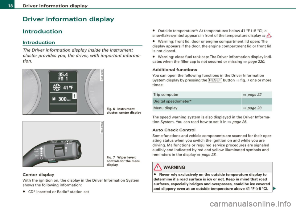
The Driver information display inside the instrument
cluster provides you , the driver, with important informa
tion.
Ce nter d isplay
Fig . 6 Inst rum ent
c lu ster : cente r dis pl ay
Fig .
7 Wiper lever :
co ntrol s for t he m enu
d isp lay
W ith th e ignition on, the displ ay in th e Driver Info rmation System
shows the follow ing information :
• CD* inserted or Radio* station set •
Outside tempe rature *: At temperatures below 41 °F ( +5 °C l, a
snowflake symbol appea rs in front of the temp erature display ~& .
• Warning: front lid , door or engine compartment l id open: The
display appears if the door, the engine compartment lid or front lid
is not closed .
• Warning : close fuel tank cap: The Driver information display indi
cates when the filler cap is not secured or missing~
page 220.
Additional fun ctions
You can open the following fun ctions in the Driver Information
System display by pressing the
I RESE T] button ~ fig. 7 one or more
times :
Trip computer Digital s peedometer*
Menu display
~ page22
~ page23
The speed warning system is also displayed in the Driver Informa
t ion System. You can read how to set it in~
page 26.
Auto Check Con trol
Some functions and vehicle componen ts are scanned for their oper
ating status when you switch the ignition on and wh ile you are
driving. Malfunc tions or required service procedures are signa led
audib ly and indicated by red and yel low illuminated symbols and
rem inders in the display~
page 28 .
& WARNING
• Never rely e xclusivel y on the outside temperature di spla y to
det ermine if a road surface is ic y or not. Keep in mind that road
s urface s, esp ec ia lly bridge s and overp asses, co uld be i ce cove red
and slippery even at an out side t emperatur e above 41 °F (+ 5
°C l. -.,
Page 22 of 320
Driver information display
Service interval display
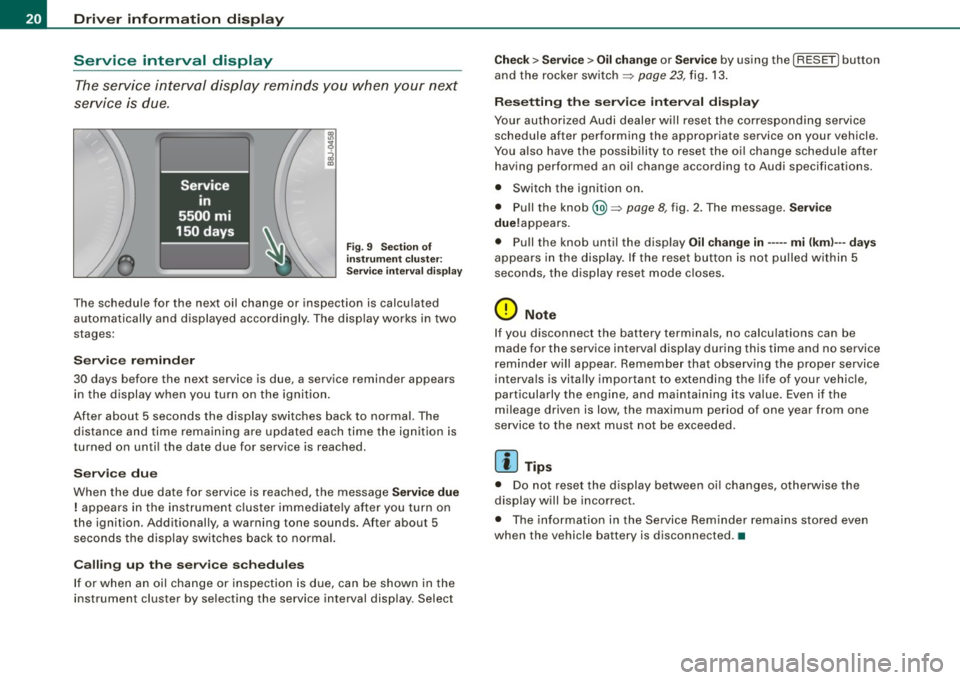
The service interval display reminds you when your next
service is due.
Fig. 9 Section of
instrument cluster:
Service interval display
The schedule for the next oil change or inspection is calculated
automatically and displayed accordingly. The display works in two
stages:
Service reminder
30 days before the next service is due, a service reminder appears in the display when you turn on the ignition.
After about 5 seconds the display switches back to normal. The distance and time remaining are updated each time the ignition is
turned on until the date due for service is reached.
Service due
When the due date for service is reached, the message Service due
! appears in the instrument cluster immediately after you turn on
the ignition. Additionally, a warning tone sounds. After about 5 seconds the display switches back to normal.
Calling up the service schedules
If or when an oil change or inspection is due, can be shown in the
instrument cluster by selecting the service interval display . Select
Check > Service > Oil change or Service by using the [ RESET! button
and the rocker switch =>
page 23, fig. 13.
Resetting the service interval display
Your authorized Audi dealer will reset the corresponding service
schedule after performing the appropriate service on your vehicle.
You also have the possibility to reset the oil change schedule after
having performed an oil change according to Audi specifications.
• Switch the ignition on.
• Pull the knob @=>
page 8, fig. 2. The message. Service
due!appears .
• Pull the knob until the display
Oil change in----- mi (kml---days
appears in the display . If the reset button is not pulled within 5
seconds, the display reset mode closes .
0 Note
If you disconnect the battery terminals, no calculations can be
made for the service interval display during this time and no service
reminder will appear. Remember that observing the proper service
intervals is vitally important to extending the life of your vehicle,
particularly the engine, and maintaining its value. Even if the
mileage driven is low, the maximum period of one year from one
service to the next must not be exceeded.
[ i] Tips
• Do not reset the display between oil changes, otherwise the
display will be incorrect.
• The information in the Service Reminder remains stored even
when the vehicle battery is disconnected .•
Page 23 of 320
On-Board Diagnostic system (08D)
On-Board Diagnostics
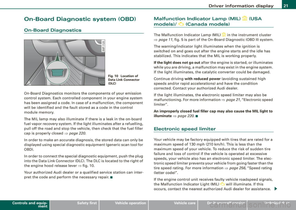
Fig. 10 location of
Data Link Connecto r
( DL C)
On-Board Diagnostics monitors the components of your emission
control system . Each controlled component in your engine system
has been assigned a code. In case of a malfunction , the component
will be identified and the fault stored as a code in the control
module memory .
The Mil lamp may also illuminate if there is a leak in the on-board
fuel vapor recovery system . If the light illuminates after a refuelling,
pull off the road and stop the vehicle, then check that the fuel filler
cap is properly closed
=> page 220 .
In order to make an accurate diagnosis, the stored data can only be
displayed using special diagnostic equipment (generic scan tool for
OBDl.
In order to connect the special diagnostic equipment, push the plug
into the Data Link Connector (DLC). The DLC is located to the right of
the engine hood re lease lever=> fig. 10.
Your authorized Audi dealer or a qualified service station can inter
pret the code and perform the necessary repair. •
Contro ls and eq uip
ment
Driver information display
Malfunction Indicator Lamp (MIL) (USA
models)/ (Canada models)
The Malfunction Indicator Lamp (MIU in the instrument cluster
=> page 11, fig . 5 is part of the On-Board Diagnostic (OBD II) system .
The warning/indicator light illuminates when the ignition is
switched on and goes out after the engine starts and the idle has
stabilized. This indicates that the Mil is working properly .
If the light does not go out after the engine is started, or illuminates
while you are driving, a ma lfunction may exist in the engine system.
If the light illuminates, the catalytic converter could be damaged.
Continue driving
with reduced power (avoiding sustained high
speeds and/or rapid accelerations) and have the condition
corrected . Contact your authorized Audi dealer.
If the light illuminates , the electronic speed limiter may also be
malfunctioning. For more information=>
page 21, "Electronic speed
limiter".
An improperly closed fuel filler cap may also cause the MIL light to
illuminate
=> page 220. •
Electronic speed limiter
Your vehicle may be factory equipped with tires that are rated for a
maximum speed of 130 mph (210 km/h) . This is less than the
maximum speed of your vehicle. To reduce the risk of sudden tire
failure and loss of control if the vehicle is operated at excessive
speeds, yo ur vehicle also has an electronic speed limiter. The elec
tronic speed limiter prevents your vehicle from going faster than the
tire speed rating. For more information
=> page 256, "Speed rating
(letter code)".
If the engine control unit receives faulty vehicle roadspeed signals,
the Malfun cti on Indicator Light (MIU will illuminate . If this
occurs, contact the nearest authori zed Audi dealer for assistance. _.,
Vehicle care I I irechnical data
Page 29 of 320
Setting speed warning 1 ~ page 27.
Speed warning 2 ,,. / (Canada models)
Storing warning 2 is recommended if you always want to be
reminded of a certain speed, for example when you are traveling in
a country that has a general maximum speed limit, or if you do not
want to exceed a specified speed for winter tires.
The speed warning 2 symbol, /
,J. (Canada models) appears in the
display when you exceed the stored speed limit. Unlike warning 1,
it will not go out until the vehicle speed drops below the stored
speed limit.
Setting speed warning 2
~ page 27.
[ i ] Tips
Even though your vehicle is equipped with a speed warning system,
you should still watch the speedometer to make sure you are not
driving faster than the speed limit. •
Speed warning 1: setting a speed limit
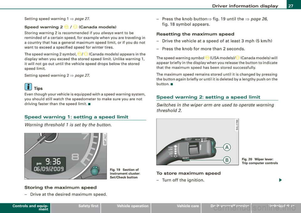
Warning threshold 1 is set by the button.
Storing the maximum speed
-Drive at the desired maximum speed .
Contro ls and eq uip
ment
Fig . 19 Section of
instrument cluster:
Set/Check button
Driver information display
- Press the knob button~ fig. 19 until the~ page 26,
fig. 18 symbol appears.
Resetting the maximum speed
- Drive the vehicle at a speed of at least 3 mph (5 km/h)
- Press the knob for more than 2 seconds.
The speed warning symbol·-(USA models) /- (Canada models) will
appear briefly in the display when you release the button to indicate
that the maximum speed has been stored successfully.
The maximum speed remains stored until it is changed by pressing
the button again briefly or until it is deleted by a lengthy push on the
button. •
Speed warning 2: setting a speed limit
Switches in the wiper arm are used to operate warning
threshold 2.
To store maximum speed
- Turn off the ignition.
Vehicle care I I
Fig. 20 Wiper lever:
Trip computer controls
irechnical data
Page 30 of 320
Driver inf ormati on displ ay
- Briefly press the button in t he ins trument cluster
=>
page 27, fig . 19. T he odome ter and the digita l clock are
now illuminated .
- Press the button for at least
2 seconds. The currently
stored maximum speed appears in the display
or the
crossed out symbol for warning threshold
2, if no
maximum speed was set previously .
- Press the function selector switch in the wiper lever @
=>
page 27, fig. 20 up or down to change t he set value .
Values r un up or dow n in steps of
6.2 mph (10 km/h) .
To dele te max imum sp eed
-Turn off the ignition.
- Briefly press the button in t he instrument cluster
=>
page 27, fig . 19. The odometer and the digita l clock are
now illuminated.
- Press the butt on for at least 2 seconds. T he currently
stored maximum speed appears in the display.
- Press the rese t button in the wiper lever @=>
page 27,
fig. 20 unt il the crossed out speed warning symbo l for
warning threshold 2 appears in the display.
A few seconds after the adjustment is comp leted, the i llumination
for the odometer and the digital clock wil l go out .
[ i ] Tip s
This warning threshold can also be controlled through the trip
computer =>
page 25, "Navigating the menu". •
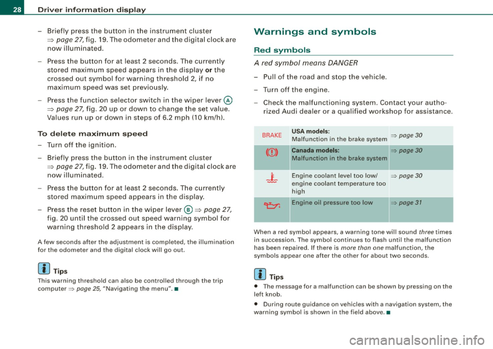
Warnings and symbols
Red symbols
A red symbol means DANGER
-Pull of the r oad and stop t he vehicle .
- Turn o ff the engine .
Check the malfunctioning system. Contact your autho
rized Audi dealer or a qua lified workshop for assistance .
BRAKE USA m odels: => page 30 Ma lfunction in the brake system
CCD > Ca na da m odel s: => page 30
Malfunction in the brake system
_t_ Engine coolant level too low/ => page 30
-engine coolant temperature too
high
~ Engine oil pressure too low => page 37
- --
When a red symbol appears, a warning tone will sound three times
in succession. The symbol continues to flash unti l the malfunction
has been repaired . If there is
more than one malfunction, the
symbols appear one after the other for about two seconds.
[ i ] Tip s
• The message for a malfunction can be shown by pressing on the
left knob.
• During route guidance on vehicles with a navigation system, the
warn ing symbo l is shown in the field above .•