steering wheel AUDI S3 SEDAN 2015 Owners Manual
[x] Cancel search | Manufacturer: AUDI, Model Year: 2015, Model line: S3 SEDAN, Model: AUDI S3 SEDAN 2015Pages: 282, PDF Size: 71.14 MB
Page 5 of 282
M N
0 > co ,...., \!) ..,.,
..,.,
..,., ,....,
Adjusting the disp lay and the warning
tones .... .. .. .. .... .... ... .. .. .... . 121
Error messages . . . . . . . . . . . . . . . . . . . . . 121
Intelligent Technology . . . . . . . . . . 122
Notice about data recorded by the Event
Data Recorder and vehicle cont rol
modules . . . . . . . . . . . . . . . . . . . . . . . . . . . 122
Electronic stabilization control (ESC) . . . . 123
Brakes . . . . . . . . . . . . . . . . . . . . . . . . . . . . . 125
Electromechanical steering . . . . . . . . . . . . 126
All wheel drive (quatt ro) . . . . . . . . . . . . . . 127
En ergy management 128
Safety . . . . . . . . . . . . . . . . . . . . . . . . . . . . 130
Driving safety . . . . . . . . . . . . . . . . . . . . 130
Basics . . . . . . . . . . . . . . . . . . . . . . . . . . . . . 130
Correct passenger seating positions..... 131
Driver's and front passenger's footwe ll . . 13 5
Pedal area . . . . . . . . . . . . . . . . . . . . . . . . . . 135
Storing cargo correct ly . . . . . . . . . . . . . . . 136
Reporting Safety Defects . . . . . . . . . . . . . . 138
Safety belt s . . . . . . . . . . . . . . . . . . . . . . 140
General notes . . . . . . . . . . . . . . . . . . . . . . . 140
Why use safety belts? . . . . . . . . . . . . . . . . 141
Safety belts . . . . . . . . . . . . . . . . . . . . . . . . 143
Belt tensioners . . . . . . . . . . . . . . . . . . . . . . 146
Airb ag sy stem . . . . . . . . . . . . . . . . . . . . 148
Important information . . . . . . . . . . . . . . . 148
Front airbags . . . . . . . . . . . . . . . . . . . . . . . 152
Monito ring the Advanced Airbag System . 160
Knee airbags . . . . . . . . . . . . . . . . . . . . . . . . 164
Side airbags . . . . . . . . . . . . . . . . . . . . . . . . 166
Side curtain airbags . . . . . . . . . . . . . . . . . . 169
Child safety . . . . . . . . . . . . . . . . . . . . . . 172
I mportant information . . . . . . . . . . . . . . . 172
Child seats . . . . . . . . . . . . . . . . . . . . . . . . . 178
Securing child seats . . . . . . . . . . . . . . . . . . 182
LATCH system (Lower anchorages and
tethers for children) . . . . . . . . . . . . . . . . . . 185
Additional information . . . . . . . . . . . . . . . 189
Table of contents
Maintenance and Care . . . . . . . . . . .
190
Checking and Filling . . . . . . . . . . . . . 190
Gasoline . . . . . . . . . . . . . . . . . . . . . . . . . . . 190
Diesel f uel . . . . . . . . . . . . . . . . . . . . . . . . . 191
Refueling . . . . . . . . . . . . . . . . . . . . . . . . . . 192
Catalytic co nverter . . . . . . . . . . . . . . . . . . . 194
D ie sel particulate filter . . . . . . . . . . . . . . . 195
Selective catalytic reduction . . . . . . . . . . . 195
En gine compartm ent . . . . . . . . . . . . . . . . . 198
Eng ine oil . . . . . . . . . . . . . . . . . . . . . . . . . . 20 1
Cooling system . . . . . . . . . . . . . . . . . . . . . . 205
Brake fluid . . . . . . . . . . . . . . . . . . . . . . . . . 207
Battery . . . . . . . . . . . . . . . . . . . . . . . . . . . . 208
Windshield washer system . . . . . . . . . . . . 212
Serv ice interval display
212
Tires and wheels . . . . . . . . . . . . . . . . . 214
Wheels . . . . . . . . . . . . . . . . . . . . . . . . . . . . 214
Tire pressure monitoring system . . . . . . . 232
Care and cleaning . . . . . . . . . . . . . . . . 235
General information . . . . . . . . . . . . . . . . . 23S
Car washes . . . . . . . . . . . . . . . . . . . . . . . . . 23S
Cleaning and care information 236
Troubleshooting . . . . . . . . . . . . . . . . . 240
Emergency assistance . . . . . . . . . . . 240
Luggage compartment lid emergency
re lease . . . . . . . . . . . . . . . . . . . . . . . . . . . . 240
General informat ion . . . . . . . . . . . . . . . . . 240
Equipm ent . . . . . . . . . . . . . . . . . . . . . . . . . 241
Replacing wheels . . . . . . . . . . . . . . . . . . . . 241
Spare tire . . . . . . . . . . . . . . . . . . . . . . . . . . 246
Fu se s and bulbs . . . . . . . . . . . . . . . . . . 248
El ectrica l fuses . . . . . . . . . . . . . . . . . . . . . . 24 8
Bulbs. . . . . . . . . . . . . . . . . . . . . . . . . . . . . . 250
Emergency situation s . . . . . . . . . . . . 252
General . . . . . . . . . . . . . . . . . . . . . . . . . . . . 252
Starting by pushing or towing . . . . . . . . . . 252
Starting with jumper cables . . . . . . . . . . . 252
Using jump start cables . . . . . . . . . . . . . . . 253
Towing with a tow truck . . . . . . . . . . . . . . . 254
Raising the vehicle . . . . . . . . . . . . . . . . . . . 256
3
Page 29 of 282
....,
N
0 > co
rl I.O
"'
"'
"'
rl
Driver information
system
Overview
App lies to vehicles: with driver information syste m
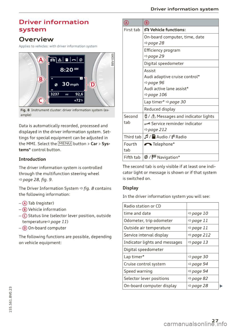
Fig. 8 Instr ument cluster : dr iver informat ion system (ex
a mp le}
Data is automatically recorded, processed and
d is played in the driver information system . Set
tings for special equipment can be adjusted in
the MMI. Select the
I MENU ! button >Car> Sys
tems* control button.
Introduction
The driver information system is controlled
through the multifunction steering wheel
¢ page 28, fig . 9.
The Driver Information System ¢ fig. 8 contains
the following information:
- @ Tab (register)
-® Vehicle information
-© S tatus line (se lector lever position, ou tside
temperature ¢
page 11)
- @ On-b oar d computer
~ M 0 :> CX) ID
The follow ing funct ions are possible, depending
on vehicle equipment:
Dri ver information system
@ ®
First tab ~ Vehicle functions:
On-board computer, time, date
¢page28
Efficiency program
¢page29
Digital speedometer
Assist
Aud i adaptive cruise control*
¢pag e 96
Audi active lane ass ist*
¢page 106
Lap timer* ¢page 30
Reduced display
Second
-!;1 / Lt Messages and indicator lights
tab
=< Service reminder indicator
¢page 212
Third tab fl I I Audio/ l'>l Radio
F ourth ,.,.
Telephone*
tab
Fifth tab
~I~ Navigation *
The second tab is only visib le if at least one indi
cator light or message is shown or if that system
is switched on.
Display
In the driver information system you will see:
Radio station or CD
time and date
¢page 10
Odometer, trip odometer ¢page 11
Outside air temperature ¢page 11
Service interval disp lay ¢ page 212
Indicator lights and messages ¢page 13
Digital speedometer
Lap t imer*
¢page30
Cruise control system ¢ page 94
Speed warn ing ¢page 94
Selector lever positions ¢page82
On-board computer display ¢page28
27
...
Page 30 of 282
Drive r in formation syste m
On-board comput er display
The on-boa rd comp uter display monitors the dif
ferent memory levels:
- Short-term memory (on-board computer 1)
- Long-term memory (on-board computer 2)
- Efficiency program
The follow ing information can be displayed in on
board computer 1 and 2 one after the other.
-Date
- Estimated range based on current fuel leve l
- Travel time
- Average consumption
- Average speed
- Distance
- Current fuel consumption
- Engine o il temperature indicator*
On -board computer
D (sho rt -term memory )
The short-term memory collects driving informa
tion from the time the ign it ion is switched on un
til it is switched off . If you continue driving with
in tw o ho ur s after sw itchi ng the ignition off, the
new values are included when calcu lating the c ur
rent trip information. If stopped for more the
two hours , the short term memory is automati
cally erased once you begin driving.
On-board com put er
fJ (long-t erm m emor y)
Unlike the short-te rm memory, the long-term
memory is not erased automat ica lly. You can se
lect the time period for evaluating trip informa
tion yourself.
E fficie ncy program
ii
The effic iency program can help you to use less
fuel ~page29.
(j) Tips
- The on-board computer is controlled by the
l eft button fields on the multifunction
steering wheel.
- For information on using the other b utton
fields, such as the audio, telephone* and navigation * functions, see the MM I owner's
manua l.
28
Operation
Applies to vehicles: with driver information system
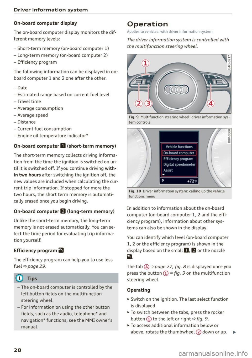
The driver information system is controlled with
the multifunction steering wheel.
Fig. 9 Mult ifunction steering wheel: driver informat ion sys
tem contro ls
Fig . 10 Dr iver info rmation system: ca lling up the vehicle
functions menu
In addition to information about the on-board
computer (on-board compu ter 1 , 2 and the effi
c iency prog ram), information about othe r sys
tems can also be shown in the display .
You can identify which level (on-board computer
1, 2 or the effi ciency program) is shown in the
display based on the small
D , fJ or the nozz le
ii .
The tab@~ page 2 7, fig. 8 is displayed once you
press the button
(D ~ fig . 9 on the m ultifunction
stee ring wheel.
Operating
"' Switch on the ignition . The last select function
is displayed .
"' To switch between the tabs, press the rocke r
button
(D t o the left or right ~ fig. 9.
"'To access add itiona l informa tion below or
above, rotate the thumbwheel @down or up.
9"'
Page 31 of 282
....,
N
0 > co
rl I.O
"'
"'
"'
rl
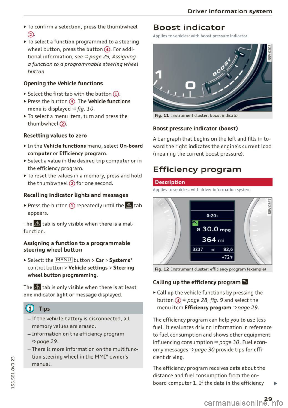
.. To confirm a selection, press the thum bwheel
@ .
.. To se lect a function programmed to a steer ing
whee l button , press the button @. For addi
tiona l information, see c:>
page 29, Assigning
a function to a programmable steering wheel
button
Opening the Vehicle functions
.. Se lect the f irst tab w ith the button (!) .
.,. Press the button @. The
Veh icle functions
menu is displayed 9 fig. 10.
.. To select a menu item, turn and press the
t hu mbwheel @.
Resetting values to zero
.. In the Vehicle funct ions menu, select On-board
computer or Efficiency program .
.. Se lect a va lue in the desired trip computer or in
t h e efficie ncy prog ram .
.,. To reset t he val ues in a memo ry, press and hold
t h e thu mbw heel @for on e secon d.
Recalling indicator lights and messages
.. Press the button CD repeated ly until the Q tab
appea rs.
The
Q tab is only visibl e when there is a mal
f u nction.
Assigning a function to a programmable
steering wheel button
.. Se lect: the I MENU j button >Car > Systems *
control button > Vehicle settings > Steering
wheel button programming .
The Q tab is only visible when there is at lea st
one ind icat or light or message displayed.
(D Tips
- If the vehicle battery is discon nected , all
memo ry values a re erased.
- In form ation on the e fficiency pr ogra m
c:> pag e 29 .
-There is more inf orm atio n on the m ultifunc
t io n st eering wheel in the MMI* owner 's
manua l.
Driver information system
Boost indicator
Applies to vehicles: with boost pressure indicator
Fig. 11 Instrume nt cl ust e r: boost in dic ato r
Boost pressure indicator (boost)
A bar grap h that begins on the l eft and fills in t o
wa rd the righ t ind icates the engine's cu rrent load
( m eaning the cur rent b oost pressure).
Efficiency program
Description
App lies to vehicles: with driver info rmation system
Fig. 12 Inst rume nt clust er: effici ency p rogram (exa mple)
Calling up the efficiency program ii1
.. Call up the veh icle functio ns by pre ss in g the
but to n @ c:>
page 2 8, fig . 9 and se lec t the
menu item
Efficiency program c:> page 29.
,._
m
T he effi ciency pro gr am can he lp y ou to use le ss
f uel.
It eval uates driving inform ati on in ref ere nce
to fuel consump tion and shows o ther eq uipme nt
i nfluencing consumpt ion c:>
page 30 . Fue l econ
omy messages
c:> page 30 provide t ips for eff i
c ient driving .
T he efficiency program rece ives data abou t the
distance and f uel consumpt ion from the on
board compu ter
1. If the data in t he eff iciency
29
Page 32 of 282
Driver information system
program is deleted ¢page 29, the values in the
on-board computer 1 are also reset.
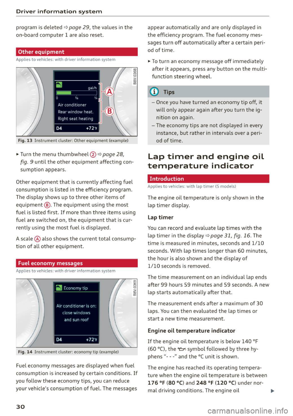
Other equipment
Applies to vehicles: with driver information system
Fig. 13 Instrument cluster: Other equ ipment (examp le)
"'T urn the menu thumbwheel @ ¢ page 28,
l8 M 0
>
"' a,
fig. 9 until the other equipment affecting con
sumption appears.
Other equipment that is currently affecting fuel
consumption is listed in the efficiency prog ram.
The display shows up to three other items of
equipment @. The equipment using the most
fue l is listed first. If more than three items using
fuel are switched on, the equ ipment that is cur
rently using the most fuel is displayed.
A scale @ also shows the current total consump
tion of all other equipment.
Fuel economy messages
Applies to vehicles: with driver information system
Fig. 14 Instrument cluster: economy tip (example)
Fuel economy messages are disp layed when fuel
consumption is increased by certain conditions . If
you follow these economy tips, you can reduce
your veh icle's consumption of fuel. The messages
30
appear automatically and are only disp layed in
the efficiency program. The fuel economy mes
sages turn off automatically after a certain per i
od of t ime.
"'T o turn an economy message off immediate ly
after it appears, press any button on the multi
function steering wheel.
(D Tips
- Once you have turned an economy tip off, it
wi ll only appear again after you turn the ig
nition on again.
- The economy tips are not displayed in every
instance, but rather in intervals over a peri
od of time.
Lap timer and engine oil
temperature indicator
Introduction
Applies to veh icles: with lap tim er (S models)
The engine oil temperature is only shown in the
lap timer display.
Lap timer
You can record and evaluate lap times with the
l ap timer in the display¢
poge 31, fig. 16. The
time is measured in minutes, seconds and 1/10
seconds. With lap times longer than 60 minutes,
the hour is also shown and the display of
1/10 seconds is removed.
The time measurement on an individua l lap ends
after 99 hours 59 minutes and 59 seconds. A new
lap starts automatically after that.
The meas urement ends after a maximum of 30
laps. You can then eva luated the lap times or
start a new time measurement.
Engine oil temperature indicator
If the engine oil temperature is below 140 °F
(60 °C), the~ symbol followed by three hy
phens" ---" and the °C unit is shown .
The engine has reached its operating tempera
ture when the engine oil tempera ture is between
176 °F (80 °() and 248 °F (120 °C) under nor-
mal driving conditions. The engine oil
IJI>
Page 34 of 282
Driver information system
® Current time measurement
@ Menu:
- Lap 1 (start)
- New lap (start another lap)
- Split time (time with in section of the
route)
- Pause (interrupts measurement)
- Statistics (evaluation of lap times)
- Rese t (all values are deleted)
Evaluating or resetting recorded times
Applies to vehicles: with lap timer (S models)
You can evaluate the fastest, slowest and aver
age lap times.
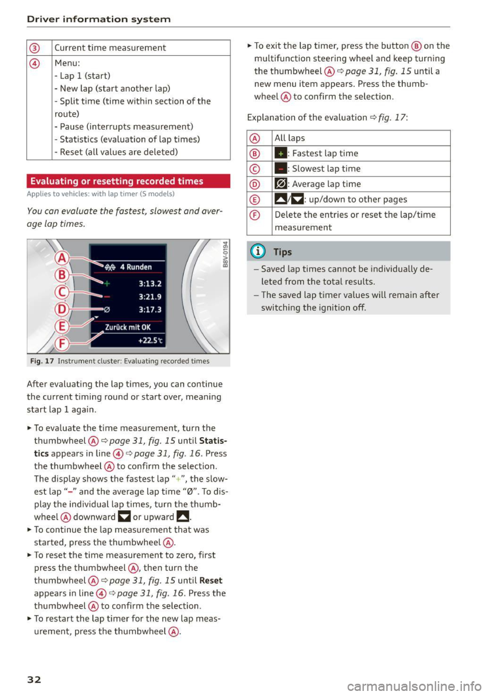
Fig. 17 Instrument cluste r: Eval uat ing reco rded t imes
After evaluating the lap times, you can continue
the current timing round or start over, meaning
start lap 1 aga in.
• To eva luate the time measurement, turn the
thumbwheel @c::>
page 31, fig. 15 until Statis
tics
appears in line@c::> page 31, fig . 16 . Press
the thumbwheel @to confirm the select ion.
The disp lay shows the fastest lap"+ ", the s low
est lap" -" and the average lap time "0". T o dis
play the individual lap times, turn the thumb
whee l@ downward
~ or upward !!.
• To continue the lap measurement that was
started, press the thumbwheel @.
• To reset the time measurement to zero, first
press the thumbwheel @, then turn the
thumbwheel @c::>page
31, fig. 15 until Reset
appears in line@i=>page31 , fig .16 . Press the
thumbwheel @to confirm the se lection .
• To restart the lap timer for the new lap meas
urement, press the thumbwheel @.
32
• To exit the lap timer, press the button @ on the
mu ltifunction steering wheel and keep turning
the thumbwheel @c::>
page 31, fig. 15 until a
new menu item appears. Press the thumb
wheel @to confirm the selection.
Explanation of the evaluation c::>
fig. 17:
@ All
laps
® II: Fastest lap time
© . : Slowest lap time
® r?l : Average lap time
® !! 1~ : up/down to other pages
© Delete the entries or reset the lap/time
measurement
@ Tips
- Saved lap times cannot be individua lly de
leted from the total results.
- The saved lap timer values will remain after
switching the ignition off.
Page 46 of 282
Light and Vision
When switched on, adaptive light adjusts to
curves depending on the vehicle speed and steer·
ing wheel angle . This provides better lighting
through the curve. The system operates in a
speed range from approximately 6 mph (10 km/
h) to 68 mph (110 km/h).
Static cornering light* (vehicles with adaptive
light)· the cornering light switches on automati
cally when the steering wheel is turned at acer
tain ang le at speeds up to approximately 44 mph
(70 km/h) and whe n the turn signal is activated
at speeds up to approximately 25 mph (40 km/
h). The area to the side of the vehicle is illuminat
ed better when tu rning.
Speed depend ent light distribution* -The speed
dependent light distribution adapts the light in
towns and on highways or expressways. In tersec
tions can also be illum inated on veh icles with a
navigat ion system*.
Highway light function*
(Vehicles with adaptive light or LED headlights) -
This function adapts the light ing for highway
driving based on vehicle speed .
..&, WARNING
-Automatic headlights* are only int ended to
assist the driver. They do not relieve the
driver of his responsibility to check the
headlights and to turn them on manually
according to the current light and visibi lity
condit ions. For example, fog cannot be de·
tected by the light sensors . So always switch
on the low beam under these weather con
ditions and when driving in the dark
io.
- Accidents could occur if you can not see the
road ahead of you well and if others on the
road cannot see you . Always switch your
head lightsonsothatyoucanseetheroad
ahead of you and others can see your vehicle
from behind.
- Please observe legal regulations when using
the lighting systems described .
44
(D Note
The rear fog lights shou ld only be turned on in
accordance with traffic regulation, as the lights are bright for following traffic.
@ Tips
-The light sensor for the automatic head
lights * is in the rearview mirror mount.
Therefore, do not place any stickers in this
area on the windshield.
- Some functions of the exterior lighting can
be adjusted
c> page 45.
- If you turn off the ignition whi le the exterior
lights are on and open the door, you will
hear a warning tone.
- In some market-specific versions, the tail
lights do not turn on when switching on the
daytime running lights.
- In cool or damp weather, the inside of the headlights, turn signals and taillights can
fog over due to the temperature difference
between the inside and outside . They will
clear shortly after switching them on. This
does not affect the serv ice life of the light
ing .
- A message will appear in the instrument
cluster if there is a malfunction in the light
sensor
c> page 24.
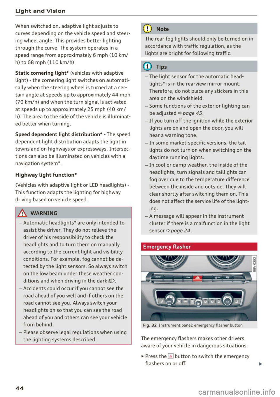
Emergency flasher
Fig. 32 Ins trumen t panel : em ergenc y flasher bu tton
The emergency flashers makes other dr ivers
aware of your vehicle in dangerous s ituations .
.. Press the~ button to switch the emergency
flashers on or off.
Page 55 of 282
M N
0 > co ...... \!) 1.1'1
1.1'1
1.1'1
......
Seats and storage
General information
Important information
A WARNING
Refer to the chapter Driving Safely
c::> page 130, Driving safety for important in
formation, tips, suggestions and warnings
that you should read and follow for your own
safety and the safety of your passengers.
Why is your seat adjustment so important?
The safety belts and the airbag system con only
provide maximum protection if the front seats
ore correctly adjusted.
There are various ways of adjusting the front
seats to provide safe and comfortable support
for the driver and the front passenger. Adjust
your seat properly so that:
- you can easily and quickly reach all the switches
and controls in the instrument panel
-your body is properly supported thus reducing
physical stress and fatigue
- the safety belts and airbag system can offer
maximum protection
c::> page 148.
In the following sections, you will see exactly
how you can best adjust your seats.
There are special regulations and instructions for
installing a child seat on the front passenger's
seat . Always follow the information regarding
child safety provided in
c::> page 172, Child safe
ty.
A WARNING
Incorrect seating position of the driver and all
other passengers can result in serious person
al injury.
- Always keep your feet on the floor when the
vehicle is in motion -never put your feet on
top of the instrument panel, out of the win
dow or on top of the seat cushion. This ap
plies especially to the passengers. If your
seating position is incorrect, you increase
Seats and storage
the risk of injury in the case of sudden brak
ing or an accident.
If the airbag inflates and
the seating position is incorrect, this could result in personal injury or even death.
- It is important for both the driver and front
passenger to keep a distance of at least
10 inches (25 cm) between themselves and
the steering wheel and/or instrument panel.
If you're sitting any closer than this, the air
bag system cannot protect you properly. In
addition, the front seats and head restraints
must be adjusted to your body height so
that they can give you maximum protection.
- Always try to keep as much distance as pos
sible between yourself and the steering
wheel or instrument panel.
- Do not adjust the driver's or front passeng
er's seat while the vehicle is moving. Your
seat may move unexpectedly, causing sud
den loss of vehicle control and personal in
jury. If you adjust your seat while the vehicle is moving, you are out of position .
Driver's seat
The correct seat position is important for safe
and relaxed driving.
We recommend that you adjust the driver's seat
in the following manner:
.,. Adjust the seat in fore and aft direction so that
you can easily push the pedals to the floor
while keeping your knees slightly bent
c::, A in
Why is your seat adjustment so important? on
page
53.
.,. Adjust the backrest so that when you sit with
your back against the backrest, you can still grasp the top of the steering wheel.
.,. For adjustable head restraints: adjust the head
restraint so the upper edge is as even as possi
ble with the top of your head.
If that is not pos
sible, try to adjust the head restraint so that it
is as close to this position as possible
c::> page 56. Move the head restraint so that it
is as close to the back of the head as possible. ..,.
53
Page 74 of 282
Driving
You must drive your vehicle about 3,000 miles (5,000 kilometers) before you can properly as
sess oil consumption.
This also applies to fuel consumption and engine
output.
@ Note
- Have your vehicle maintained properly and
in accordance w ith the service recommenda
tions in your Warranty
& Maintenance book
let. Lack of proper maintenance as well as
improper use of the vehicle will impair the
function of the emission control system and
could lead to damage.
- Do not alter or remove any component of the Emission Control System unless approved by the manufacturer.
- Do not alter or remove any device, such as heat shields, switches, ignition wires,
valves, which are designed to protect your
vehicle's Emission Control System and other important vehicle components.
Fewer short trips
Fuel consumption will always be relatively high
on short trips.
.,. Try to avoid driving short distances with a cold
engine.
The eng ine and catalytic converter have to reach
their optimal
operating temperature to reduce
fuel consumption and noxious emissions effec
tively .
Just after starting, a cold engine in a mid-size car only achieves a fuel economy of 6-8 miles per
gallon (30-40 l/100 km). After about a half a mile, fuel economy climbs to 12 mpg (20
l/
100 km) . After about 2.5 miles (4 km), the en
gine is at its proper operating temperature and
fuel economy has reached a normal level. So you
can see that you should avoid short trips whenev
er possible.
The
outside temperature is also critical in this re
gard. Your car consumes more fuel in the winter
than in the summer.
72
Steering
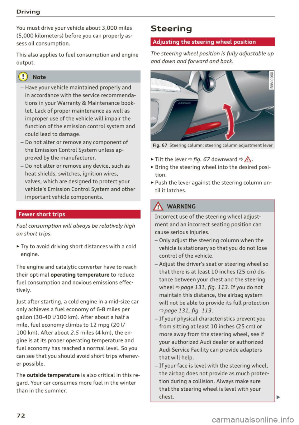
Adjusting the steering wheel position
The steering wheel position is fully adjustable up
and down and forward and back .
Fig. 67 Ste ering co lumn : steer ing colu mn adjus tmen t l eve r
.,. Tilt the lever ¢ fig. 67 downward ¢.&, .
.,. Bring the steering wheel into the desired posi
tion.
.,. Push the lever against the steering column un
til it latches .
A WARNING
Incorrect use of the steering wheel adjust
ment and an incorrect seating position can
cause serious injuries.
- Only adjust the steering column when the
vehicle is stationary so that you do not lose
control of the vehicle.
-
-Adjust the driver's seat or steer ing wheel so
that there is at least 10 inches (25 cm) dis
tance between your chest and the steering
wheel ¢
page 131, fig. 113. If you do not
maintain this distance, the airbag system
will not be able to provide its full protection
¢page 131, fig. 113.
-If your physical characteristics prevent you
from sitting at least 10 inches (25 cm) or
more away from the steering wheel, see if
your authorized Audi dealer or authorized
Audi Service Facility can provide adapters that will help.
- If your face is level with the steering wheel,
the airbag does not provide as much protec
tion during a collision . Always make sure
that the steering wheel is level with your
chest .
Page 75 of 282
....,
N
-Always hold the steering wheel with your
hands in the 9 o'clock and 3 o'clock posi
tions to reduce the risk of injury if the airbag
deploys .
- Never hold the steer ing wheel in the 12
o'clock position or w ith both hands on the
rim or the center of the steering wheel.
Holding the stee ring wheel incorrectly sig
nificantly increases the risk of injury to the
hands, arms and head if the airbag deploys.
Starting and stopping
the engine (vehicles with an ignition lock)
Starting the engine with the key
Applies to vehicles: with mechanical ignit ion lock
The ignition is switched on and the engine start
ed with the key in the ignition .
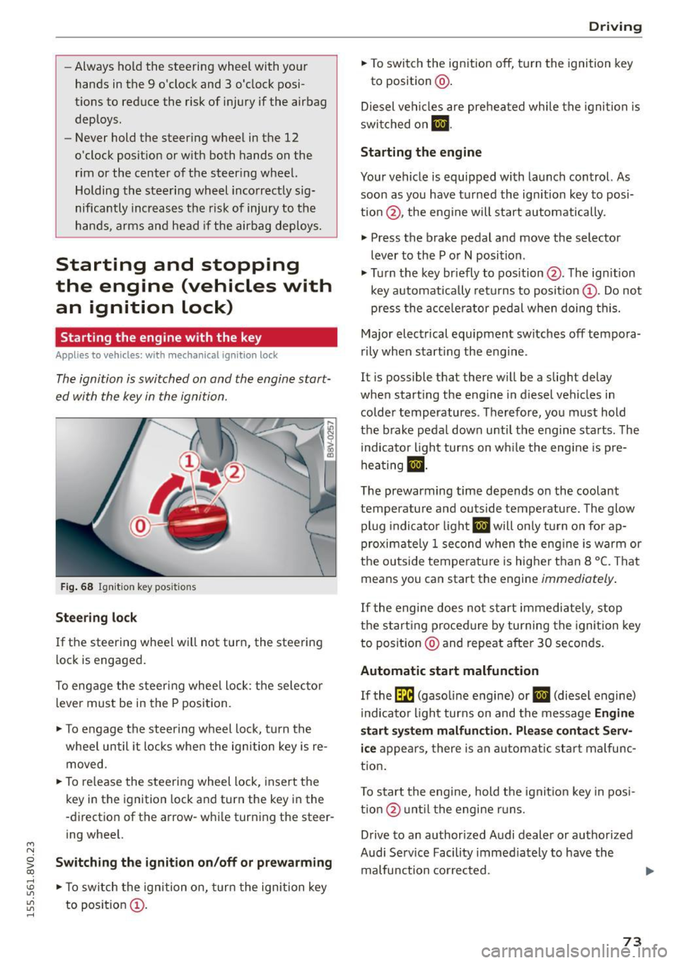
Fig . 68 Ignit io n key pos it io n s
Stee ring l ock
If the steering wheel wil l not turn, the steering
lock is engaged.
To engage the steering wheel lock : the selector
l ever must be in the P position.
.,. To engage the steering w heel lock, turn the
whee l until it locks whe n the ignition key is re
moved.
.,. To re lease the steering wheel lock , insert the
key in the ignition lock and turn the key in the
-direction of the arrow-while turning the steer
ing wheel.
~ Swit ching the ignition on /off or prew arming co
rl I.O
"'
"'
"'
rl
.,. To sw itch the ignition on, turn the ignition key
to position @.
Dr ivi ng
.,. To switch the ignition off, turn the ignition key
to posit ion @.
Diesel vehicles are preheated while the ignition is
swi tched on
m .
Starting the engine
Your vehicle is equipped with launch control. As
soon as you have turned the ign ition key to posi
tion @, the engine will start automatically.
.,. Press the brake pedal and move the selector
lever to the P or
N position .
.,. Turn the key br iefly to position @. The ign ition
key automatically retu rns to position @. Do not
press the a cce le rator pedal when doing this.
Major electrical equipment switches off tempora
rily when start ing the engine .
It is possible that there w ill be a slight delay
when starting the eng ine in diesel vehicles in
colder temperatures . T herefore, you must hold
the brake pedal down unti l the engine starts . The
indicator light turns on wh ile the engine is pre
hea ting
lJ .
The prewarming time depends on the coolant
temperature and outside temperatu re. The glow
pl ug indicato r light
IJ will only turn on for ap
proximate ly 1 second when the eng ine is warm or
the outside tempe rature is higher than 8
°C. That
means you can start the engine
immediately .
If the engine does no t st art immediately, stop
the start ing procedure by turning the ignition key
to position @and repeat after 30 seconds.
Automatic start malfunction
If the (m (gasoline engine) or IJ (diesel engine)
i ndicato r light turns on and the message
Engine
start sy ste m malfunction . Plea se c ontact S erv
i c e
appea rs, there is an automatic sta rt malfunc
t ion .
T o start the engine, hold the ignit io n key in posi
tio n@ unt il the engine r uns.
Drive to an authorized Audi dealer or authorized
Audi Se rv ice Facility immed iately to have the
malfunction corrected. ..,.
73