AUDI S4 1998 B5 / 1.G Engine Manual
Manufacturer: AUDI, Model Year: 1998, Model line: S4, Model: AUDI S4 1998 B5 / 1.GPages: 72, PDF Size: 3.25 MB
Page 61 of 72
62
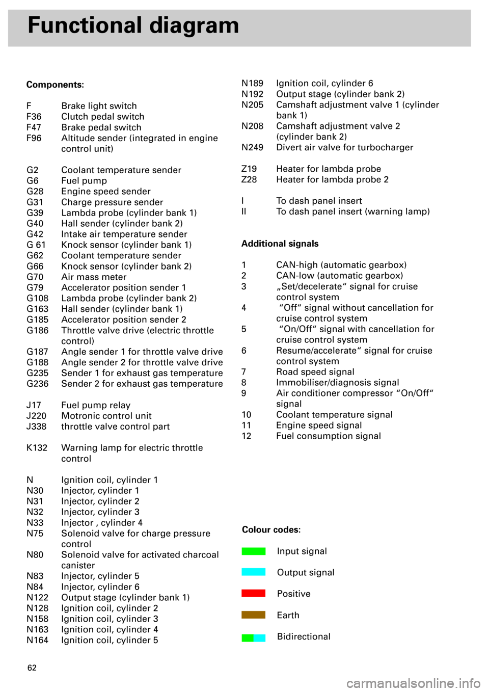
Functional diagram
Components:
F Brake light switch
F36 Clutch pedal switch
F47 Brake pedal switch
F96 Altitude sender (integrated in engine
control unit)
G2 Coolant temperature sender
G6 Fuel pump
G28 Engine speed sender
G31 Charge pressure sender
G39 Lambda probe (cylinder bank 1)
G40 Hall sender (cylinder bank 2)
G42 Intake air temperature sender
G 61 Knock sensor (cylinder bank 1)
G62 Coolant temperature sender
G66 Knock sensor (cylinder bank 2)
G70 Air mass meter
G79 Accelerator position sender 1
G108 Lambda probe (cylinder bank 2)
G163 Hall sender (cylinder bank 1)
G185 Accelerator position sender 2
G186 Throttle valve drive (electric throttle
control)
G187 Angle sender 1 for throttle valve drive
G188 Angle sender 2 for throttle valve drive
G235 Sender 1 for exhaust gas temperature
G236 Sender 2 for exhaust gas temperature
J17 Fuel pump relay
J220 Motronic control unit
J338 throttle valve control part
K132 Warning lamp for electric throttle
control
N Ignition coil, cylinder 1
N30 Injector, cylinder 1
N31 Injector, cylinder 2
N32 Injector, cylinder 3
N33 Injector , cylinder 4
N75 Solenoid valve for charge pressure
control
N80 Solenoid valve for activated charcoal
canister
N83 Injector, cylinder 5
N84 Injector, cylinder 6
N122 Output stage (cylinder bank 1)
N128 Ignition coil, cylinder 2
N158 Ignition coil, cylinder 3
N163 Ignition coil, cylinder 4
N164 Ignition coil, cylinder 5N189 Ignition coil, cylinder 6
N192 Output stage (cylinder bank 2)
N205 Camshaft adjustment valve 1 (cylinder
bank 1)
N208 Camshaft adjustment valve 2
(cylinder bank 2)
N249 Divert air valve for turbocharger
Z19 Heater for lambda probe
Z28 Heater for lambda probe 2
I To dash panel insert
II To dash panel insert (warning lamp)
Additional signals
1 CAN-high (automatic gearbox)
2 CAN-low (automatic gearbox)
3 „Set/decelerate“ signal for cruise
control system
4 “Off“ signal without cancellation for
cruise control system
5 “On/Off“ signal with cancellation for
cruise control system
6 Resume/accelerate“ signal for cruise
control system
7 Road speed signal
8 Immobiliser/diagnosis signal
9 Air conditioner compressor “On/Off“
signal
10 Coolant temperature signal
11 Engine speed signal
12 Fuel consumption signal
Colour codes:
Input signal
Output signal
Positive
Earth
Bidirectional
Page 62 of 72
63
M
30
15
31
31 31
30
15
31
_
G6N31
N32N33N80
J220
N83N84
N30
N75
N249
N205
N208
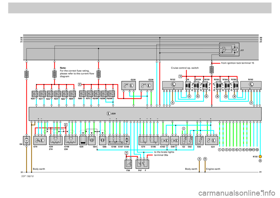
SSP 198/18
G235
G236
G31
N N128J17
N158 N163 N164 N189
Q PPPPPP
QQ QQQ
A
A
B Z
ZB
B
B
N122
A
B
B
B
1
N192
G61
G66 G188 G187 G186 G79
F47 F36 FG163 G40 G62G2 G42
K132 G185
G28 G70 G39
Z19G108
Z28
Y
+
Y
I
2
3
4
5
6
7
8
9
10
11
12
II
l
l
t° t°
m
lt° t° t°
+++ +
Cruise control op. switch
from ignition lock terminal 15
to the brake lightsterminal 30a
Body earth
Engine earth
Note:
For the correct fuse rating,
please refer to the current flow
diagram
Body earth
Page 63 of 72
64
SSP 198/39
Self-diagnosis
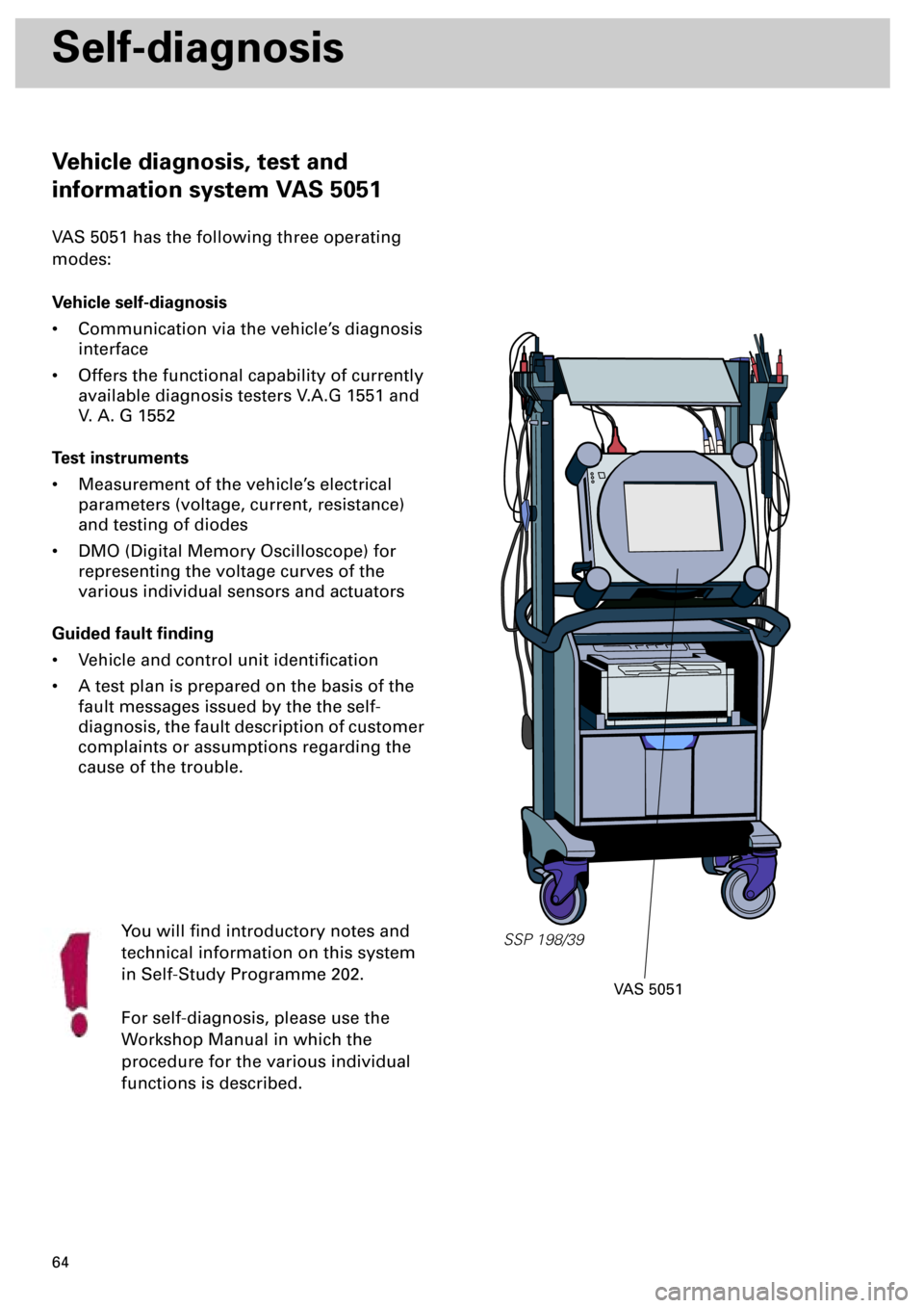
Vehicle diagnosis, test and
information system VAS 5051
VAS 5051 has the following three operating
modes:
Vehicle self-diagnosis
• Communication via the vehicle’s diagnosis
interface
• Offers the functional capability of currently
available diagnosis testers V.A.G 1551 and
V. A. G 1552
Test instruments
• Measurement of the vehicle’s electrical
parameters (voltage, current, resistance)
and testing of diodes
• DMO (Digital Memory Oscilloscope) for
representing the voltage curves of the
various individual sensors and actuators
Guided fault finding
• Vehicle and control unit identification
• A test plan is prepared on the basis of the
fault messages issued by the the self-
diagnosis, the fault description of customer
complaints or assumptions regarding the
cause of the trouble.
You will find introductory notes and
technical information on this system
in Self-Study Programme 202.
For self-diagnosis, please use the
Workshop Manual in which the
procedure for the various individual
functions is described.
VAS 5051
Page 64 of 72
65
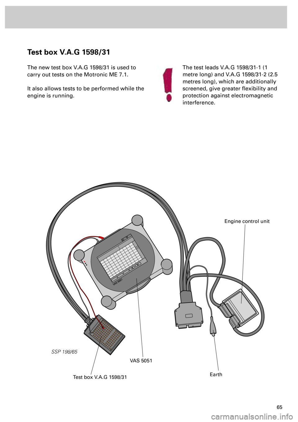
Test box V.A.G 1598/31
The new test box V.A.G 1598/31 is used to
carry out tests on the Motronic ME 7.1.
It also allows tests to be performed while the
engine is running.
VAS 5051VAS 5051
SSP 198/65
VAS 5051
Test box V.A.G 1598/31
Engine control unit
Earth
The test leads V.A.G 1598/31-1 (1
metre long) and V.A.G 1598/31-2 (2.5
metres long), which are additionally
screened, give greater flexibility and
protection against electromagnetic
interference.
Page 65 of 72
66
Power Transmission
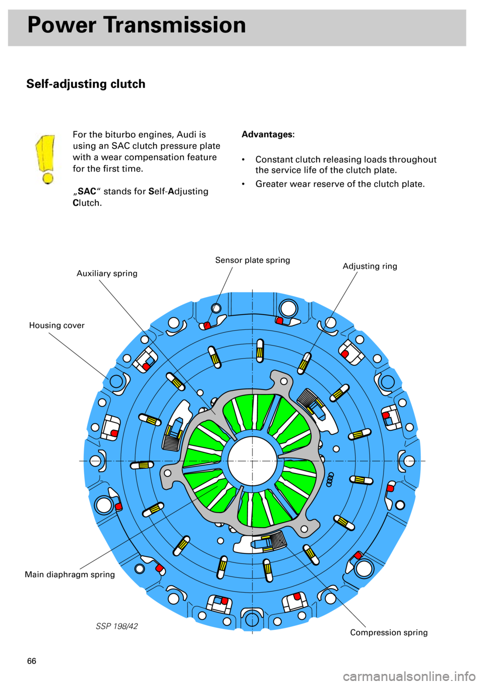
Self-adjusting clutch
Advantages:
• Constant clutch releasing loads throughout
the service life of the clutch plate.
• Greater wear reserve of the clutch plate. For the biturbo engines, Audi is
using an SAC clutch pressure plate
with a wear compensation feature
for the first time.
„
SAC
“ stands for
S
elf-
A
djusting
C
lutch.
SSP 198/42
Auxiliary spring
Adjusting ringSensor plate spring
Main diaphragm spring
Compression spring
Housing cover
Page 66 of 72
67
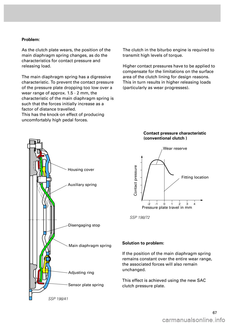
Problem:
As the clutch plate wears, the position of the
main diaphragm spring changes, as do the
characteristics for contact pressure and
releasing load.
The main diaphragm spring has a digressive
characteristic. To prevent the contact pressure
of the pressure plate dropping too low over a
wear range of approx. 1.5 - 2 mm, the
characteristic of the main diaphragm spring is
such that the forces initially increase as a
factor of distance travelled.
This has the knock-on effect of producing
uncomfortably high pedal forces.
The clutch in the biturbo engine is required to
transmit high levels of torque.
Higher contact pressures have to be applied to
compensate for the limitations on the surface
area of the clutch lining for design reasons.
This in turn results in higher releasing loads
(particularly as wear progresses).
Solution to problem:
If the position of the main diaphragm spring
remains constant over the entire wear range,
the associated forces will also remain
unchanged.
This effect is achieved using the new SAC
clutch pressure plate.
SSP 198/41
Housing cover
SSP 198/72
0 -1 -2 1 2 3 4
Pressure plate travel in mm
Contact pressure
Fitting location
Wear reserve
Contact pressure characteristic
(conventional clutch )
Sensor plate spring
Main diaphragm spring
Adjusting ring
Auxiliary spring
Disengaging stop
Page 67 of 72
68
Power Transmission
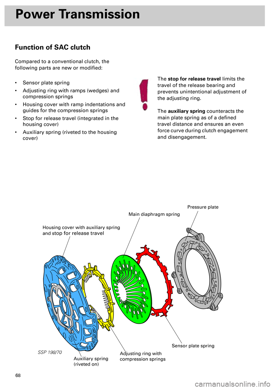
Function of SAC clutch
Compared to a conventional clutch, the
following parts are new or modified:
• Sensor plate spring
• Adjusting ring with ramps (wedges) and
compression springs
• Housing cover with ramp indentations and
guides for the compression springs
• Stop for release travel (integrated in the
housing cover)
• Auxiliary spring (riveted to the housing
cover)The
stop for release travel
limits the
travel of the release bearing and
prevents unintentional adjustment of
the adjusting ring.
The
auxiliary spring
counteracts the
main plate spring as of a defined
travel distance and ensures an even
force curve during clutch engagement
and disengagement.
SSP 198/70
Housing cover with auxiliary spring
and s
top for release travel
Main diaphragm spring
Pressure plate
Auxiliary spring
(riveted on)
Sensor plate spring
Adjusting ring with
compression springs
Page 68 of 72
69
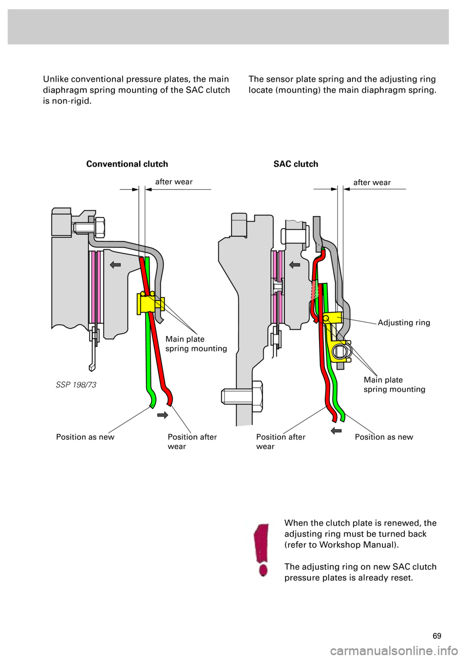
Unlike conventional pressure plates, the main
diaphragm spring mounting of the SAC clutch
is non-rigid.
When the clutch plate is renewed, the
adjusting ring must be turned back
(refer to Workshop Manual).
The adjusting ring on new SAC clutch
pressure plates is already reset.
The sensor plate spring and the adjusting ring
locate (mounting) the main diaphragm spring.
SSP 198/73
after wear
after wear
Position as newPosition after
wearPosition as newPosition after
wear
Main plate
spring mounting
Main plate
spring mounting
Conventional clutch
SAC clutch
Adjusting ring
Page 69 of 72
70
Power transmission
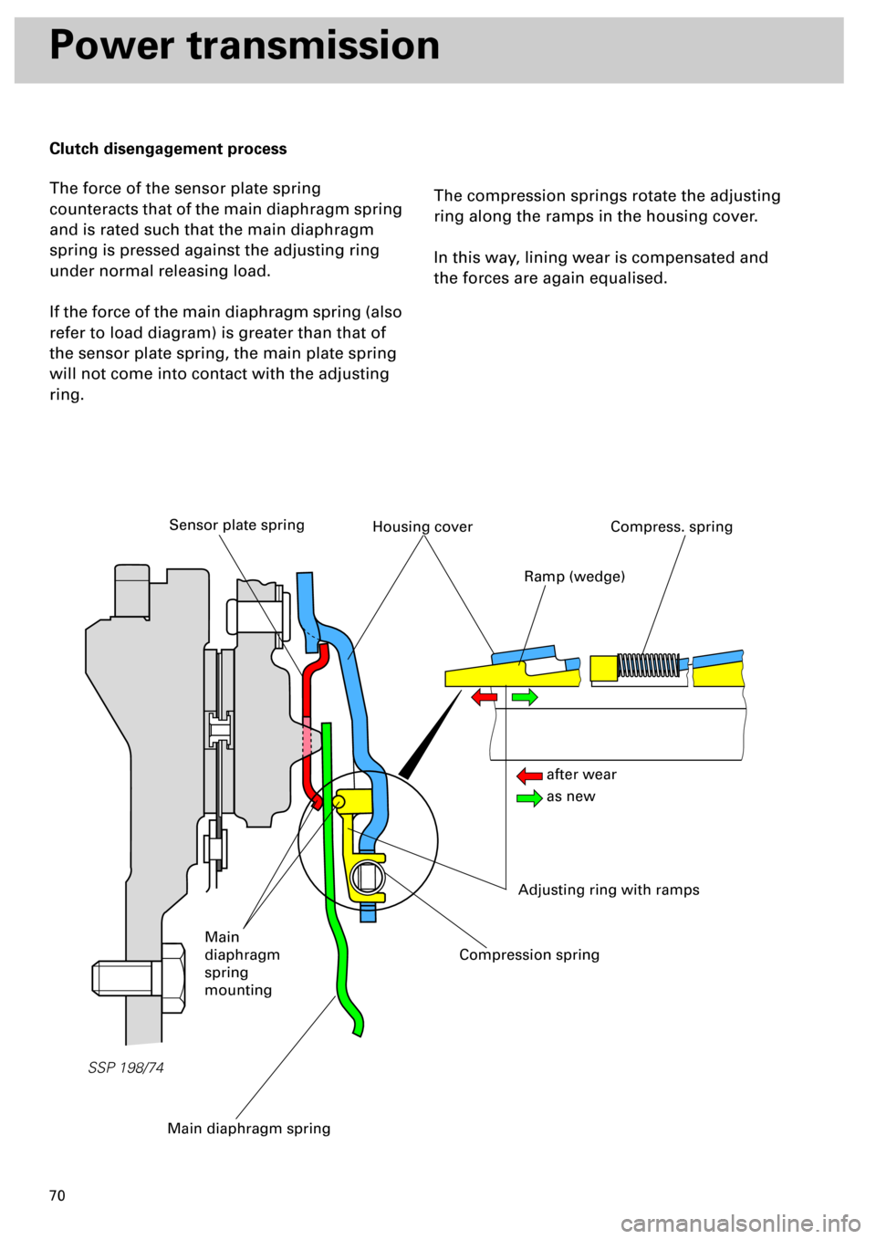
Clutch disengagement process
The force of the sensor plate spring
counteracts that of the main diaphragm spring
and is rated such that the main diaphragm
spring is pressed against the adjusting ring
under normal releasing load.
If the force of the main diaphragm spring (also
refer to load diagram) is greater than that of
the sensor plate spring, the main plate spring
will not come into contact with the adjusting
ring.
The compression springs rotate the adjusting
ring along the ramps in the housing cover.
In this way, lining wear is compensated and
the forces are again equalised.
SSP 198/74
Main diaphragm spring
Sensor plate springHousing cover
Adjusting ring with ramps
Compress. spring
Compression spring
Main
diaphragm
spring
mounting
Ramp (wedge)
after wear
as new
Page 70 of 72
71
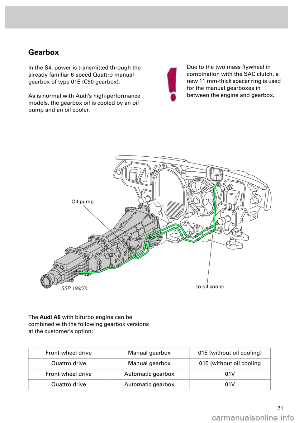
Gearbox
In the S4, power is transmitted through the
already familiar 6-speed Quattro manual
gearbox of type 01E (C90 gearbox).
As is normal with Audi’s high-performance
models, the gearbox oil is cooled by an oil
pump and an oil cooler.
The
Audi A6
with biturbo engine can be
combined with the following gearbox versions
at the customer’s option:
Front-wheel drive Manual gearbox 01E (without oil cooling)
Quattro drive Manual gearbox 01E (without oil cooling
Front-wheel drive Automatic gearbox 01V
Quattro drive Automatic gearbox 01V
Due to the two mass flywheel in
combination with the SAC clutch, a
new 11 mm-thick spacer ring is used
for the manual gearboxes in
between the engine and gearbox.
SSP 198/76
to oil cooler
Oil pump