n249 AUDI S4 1998 B5 / 1.G Engine Manual
[x] Cancel search | Manufacturer: AUDI, Model Year: 1998, Model line: S4, Model: AUDI S4 1998 B5 / 1.GPages: 72, PDF Size: 3.25 MB
Page 19 of 72
20
Engine
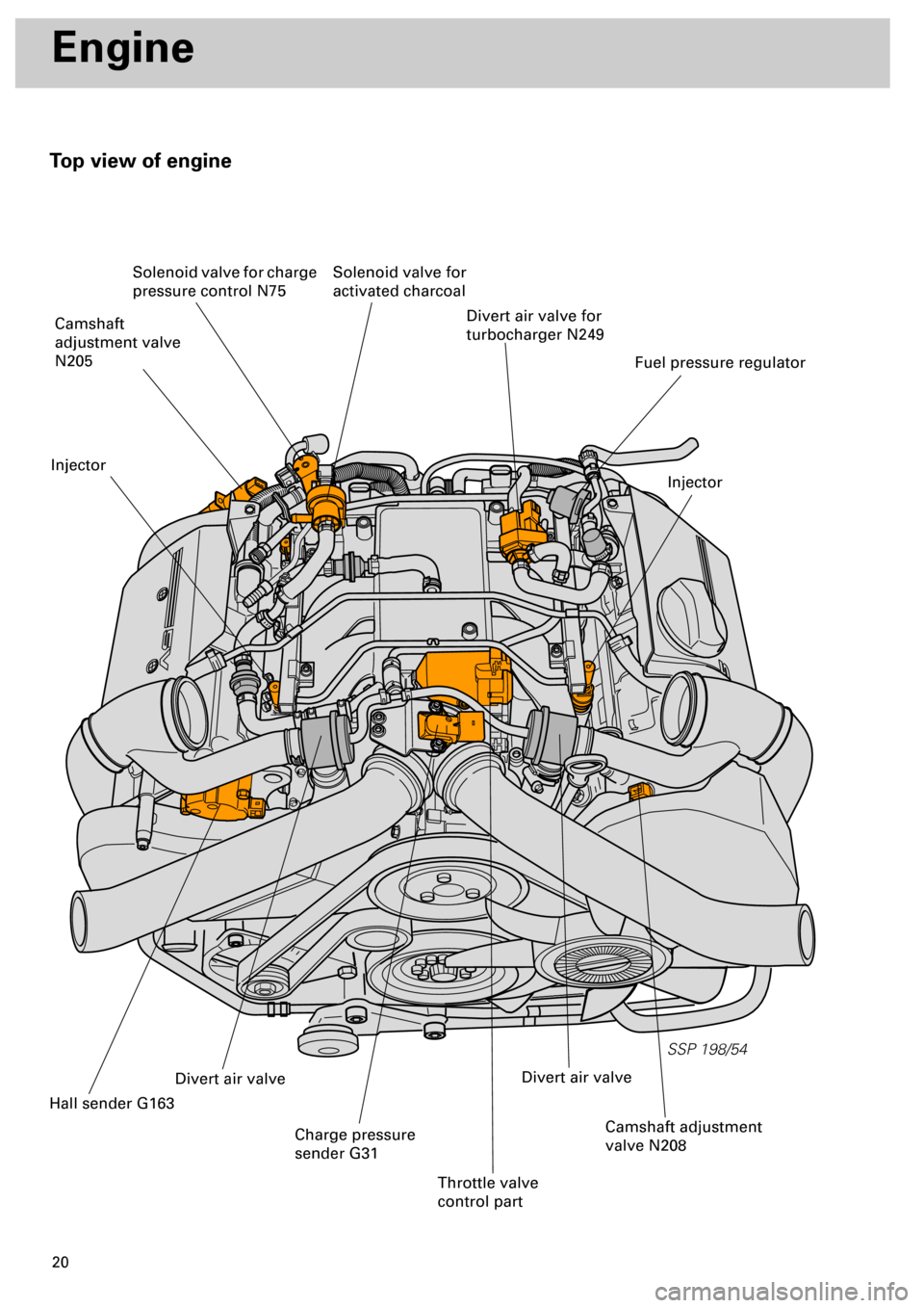
Top view of engine
SSP 198/54
Divert air valve for
turbocharger N249
Injector
Fuel pressure regulator
Solenoid valve for
activated charcoal Solenoid valve for charge
pressure control N75
Camshaft
adjustment valve
N205
Injector
Hall sender G163
Divert air valve
Charge pressure
sender G31
Throttle valve
control part
Camshaft adjustment
valve N208
Divert air valve
Page 24 of 72
25
SSP 198/31
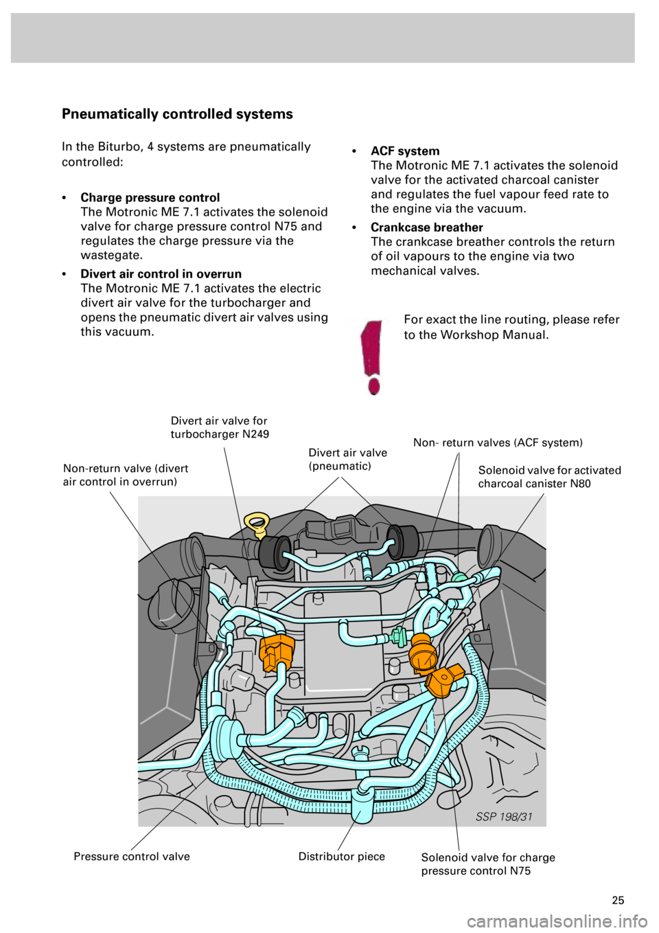
Pneumatically controlled systems
In the Biturbo, 4 systems are pneumatically
controlled:
•
Charge pressure control
The Motronic ME 7.1 activates the solenoid
valve for charge pressure control N75 and
regulates the charge pressure via the
wastegate.
•
Divert air control in overrun
The Motronic ME 7.1 activates the electric
divert air valve for the turbocharger and
opens the pneumatic divert air valves using
this vacuum.
•
ACF system
The Motronic ME 7.1 activates the solenoid
valve for the activated charcoal canister
and regulates the fuel vapour feed rate to
the engine via the vacuum.
•
Crankcase breather
The crankcase breather controls the return
of oil vapours to the engine via two
mechanical valves.
Solenoid valve for charge
pressure control N75
Solenoid valve for activated
charcoal canister N80
Divert air valve for
turbocharger N249
Non- return valves (ACF system)
Distributor piecePressure control valve
Non-return valve (divert
air control in overrun)
Divert air valve
(pneumatic)
For exact the line routing, please refer
to the Workshop Manual.
Page 27 of 72
28
SSP 198/05
Engine
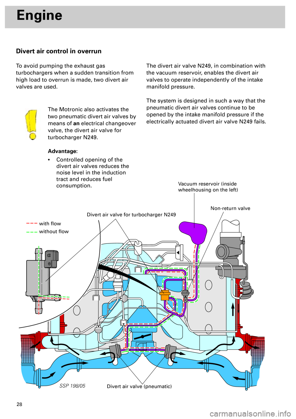
Divert air control in overrun
To avoid pumping the exhaust gas
turbochargers when a sudden transition from
high load to overrun is made, two divert air
valves are used.
The Motronic also activates the
two pneumatic divert air valves by
means of
an
electrical changeover
valve, the divert air valve for
turbocharger N249.
Advantage:
•
Controlled opening of the
divert air valves reduces the
noise level in the induction
tract and reduces fuel
consumption.
The divert air valve N249, in combination with
the vacuum reservoir, enables the divert air
valves to operate independently of the intake
manifold pressure.
The system is designed in such a way that the
pneumatic divert air valves continue to be
opened by the intake manifold pressure if the
electrically actuated divert air valve N249 fails.
Divert air valve for turbocharger N249
Vacuum reservoir (inside
wheelhousing on the left)
Divert air valve (pneumatic)
with flow
without flow
Non-return valve
Page 61 of 72
62
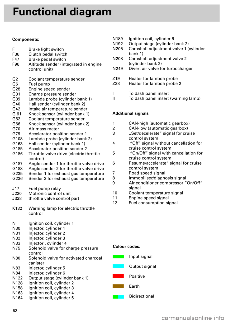
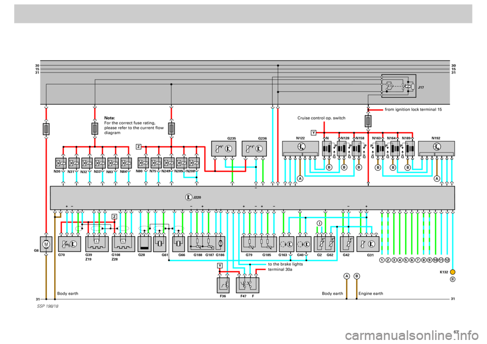
Functional diagram
Components:
F Brake light switch
F36 Clutch pedal switch
F47 Brake pedal switch
F96 Altitude sender (integrated in engine
control unit)
G2 Coolant temperature sender
G6 Fuel pump
G28 Engine speed sender
G31 Charge pressure sender
G39 Lambda probe (cylinder bank 1)
G40 Hall sender (cylinder bank 2)
G42 Intake air temperature sender
G 61 Knock sensor (cylinder bank 1)
G62 Coolant temperature sender
G66 Knock sensor (cylinder bank 2)
G70 Air mass meter
G79 Accelerator position sender 1
G108 Lambda probe (cylinder bank 2)
G163 Hall sender (cylinder bank 1)
G185 Accelerator position sender 2
G186 Throttle valve drive (electric throttle
control)
G187 Angle sender 1 for throttle valve drive
G188 Angle sender 2 for throttle valve drive
G235 Sender 1 for exhaust gas temperature
G236 Sender 2 for exhaust gas temperature
J17 Fuel pump relay
J220 Motronic control unit
J338 throttle valve control part
K132 Warning lamp for electric throttle
control
N Ignition coil, cylinder 1
N30 Injector, cylinder 1
N31 Injector, cylinder 2
N32 Injector, cylinder 3
N33 Injector , cylinder 4
N75 Solenoid valve for charge pressure
control
N80 Solenoid valve for activated charcoal
canister
N83 Injector, cylinder 5
N84 Injector, cylinder 6
N122 Output stage (cylinder bank 1)
N128 Ignition coil, cylinder 2
N158 Ignition coil, cylinder 3
N163 Ignition coil, cylinder 4
N164 Ignition coil, cylinder 5N189 Ignition coil, cylinder 6
N192 Output stage (cylinder bank 2)
N205 Camshaft adjustment valve 1 (cylinder
bank 1)
N208 Camshaft adjustment valve 2
(cylinder bank 2)
N249 Divert air valve for turbocharger
Z19 Heater for lambda probe
Z28 Heater for lambda probe 2
I To dash panel insert
II To dash panel insert (warning lamp)
Additional signals
1 CAN-high (automatic gearbox)
2 CAN-low (automatic gearbox)
3 „Set/decelerate“ signal for cruise
control system
4 “Off“ signal without cancellation for
cruise control system
5 “On/Off“ signal with cancellation for
cruise control system
6 Resume/accelerate“ signal for cruise
control system
7 Road speed signal
8 Immobiliser/diagnosis signal
9 Air conditioner compressor “On/Off“
signal
10 Coolant temperature signal
11 Engine speed signal
12 Fuel consumption signal
Colour codes:
Input signal
Output signal
Positive
Earth
Bidirectional
Page 62 of 72
63
M
30
15
31
31 31
30
15
31
_
G6N31
N32N33N80
J220
N83N84
N30
N75
N249
N205
N208
SSP 198/18
G235
G236
G31
N N128J17
N158 N163 N164 N189
Q PPPPPP
QQ QQQ
A
A
B Z
ZB
B
B
N122
A
B
B
B
1
N192
G61
G66 G188 G187 G186 G79
F47 F36 FG163 G40 G62G2 G42
K132 G185
G28 G70 G39
Z19G108
Z28
Y
+
Y
I
2
3
4
5
6
7
8
9
10
11
12
II
l
l
t° t°
m
lt° t° t°
+++ +
Cruise control op. switch
from ignition lock terminal 15
to the brake lightsterminal 30a
Body earth
Engine earth
Note:
For the correct fuse rating,
please refer to the current flow
diagram
Body earth