throttle AUDI S4 1998 B5 / 1.G Engine Manual
[x] Cancel search | Manufacturer: AUDI, Model Year: 1998, Model line: S4, Model: AUDI S4 1998 B5 / 1.GPages: 72, PDF Size: 3.25 MB
Page 2 of 72
2
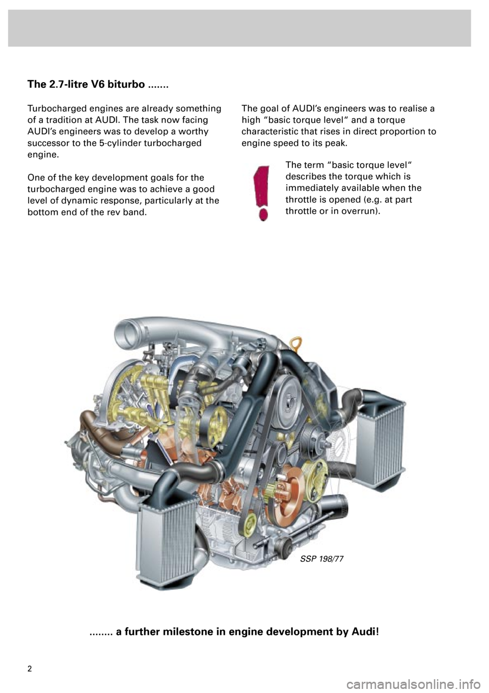
The 2.7-litre V6 biturbo .......
Turbocharged engines are already something
of a tradition at AUDI. The task now facing
AUDI’s engineers was to develop a worthy
successor to the 5-cylinder turbocharged
engine.
One of the key development goals for the
turbocharged engine was to achieve a good
level of dynamic response, particularly at the
bottom end of the rev band.
........ a further milestone in engine development by Audi!
The goal of AUDI’s engineers was to realise a
high “basic torque level“ and a torque
characteristic that rises in direct proportion to
engine speed to its peak.
The term “basic torque level“
describes the torque which is
immediately available when the
throttle is opened (e.g. at part
throttle or in overrun).
SSP 198/77
Page 3 of 72
3
This Self-study Programme provides you with information
regarding design and function.
The Self-study Programme is not a Workshop Manual!
Please refer to the Service Literature for all the relevant
maintenance and repair instructions.
Page
Engine .........................................................
Technical data, crankshaft, cylinder head,
camshaft timing, cooling circuit, engine
lubrication, overview of components, air ducting,
charging, exhaust system, pneumatically
controlled systems, charge pressure control, air
divert control in overrun, ACF system, crankcase
breather
4
Motronic ME 7.1 ..........................................
Subfunctions, system overview
31
Subsystems of the Motronic .....................
Torque-oriented engine management, torque-
oriented functional structure, Electronic throttle,
exhaust gas temperature control
33
Sensors .......................................................
Additional sensors of the Motronic
49
Auxiliary signals/interfaces ...................... 57
Functional diagram ..................................... 62
Self-diagnosis .............................................
Vehicle diagnosis, test and information system
VAS 5051, test box V.A.G 1598/31
64
Transmission ..............................................
Self-adjusting clutch, gearbox
66
Contents
Important!/Note!
New!
Page 8 of 72
8
Engine
The variable valve timing
The camshaft timing has been modified
compared to the 2.8-litre V6 engine to meet the
demands of turbocharging technology.
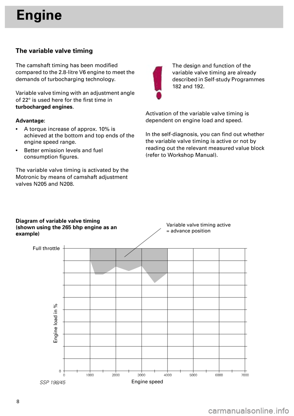
Variable valve timing with an adjustment angle
of 22° is used here for the first time in
turbocharged engines
.
Advantage:
•
A torque increase of approx. 10% is
achieved at the bottom and top ends of the
engine speed range.
•
Better emission levels and fuel
consumption figures.
The variable valve timing is activated by the
Motronic by means of camshaft adjustment
valves N205 and N208.The design and function of the
variable valve timing are already
described in Self-study Programmes
182 and 192.
Activation of the variable valve timing is
dependent on engine load and speed.
In the self-diagnosis, you can find out whether
the variable valve timing is active or not by
reading out the relevant measured value block
(refer to Workshop Manual).
0
0 1000 2000 3000 4000 5000 6000 7000
SSP 198/45
Diagram of variable valve timing
(shown using the 265 bhp engine as an
example)
Engine speed
Engine load in %
Variable valve timing active
= advance position
Full throttle
Page 19 of 72
20
Engine
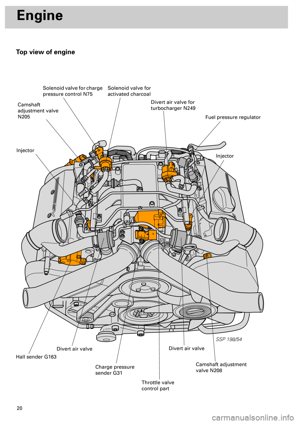
Top view of engine
SSP 198/54
Divert air valve for
turbocharger N249
Injector
Fuel pressure regulator
Solenoid valve for
activated charcoal Solenoid valve for charge
pressure control N75
Camshaft
adjustment valve
N205
Injector
Hall sender G163
Divert air valve
Charge pressure
sender G31
Throttle valve
control part
Camshaft adjustment
valve N208
Divert air valve
Page 21 of 72
22
SSP 198/04
Engine
Air ducting
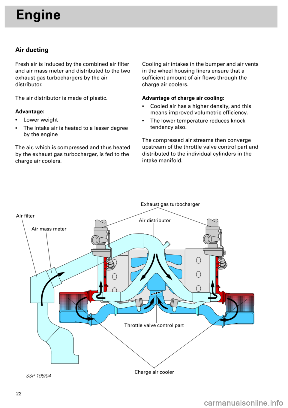
Fresh air is induced by the combined air filter
and air mass meter and distributed to the two
exhaust gas turbochargers by the air
distributor.
The air distributor is made of plastic.
Advantage:
•
Lower weight
•
The intake air is heated to a lesser degree
by the engine
The air, which is compressed and thus heated
by the exhaust gas turbocharger, is fed to the
charge air coolers.Cooling air intakes in the bumper and air vents
in the wheel housing liners ensure that a
sufficient amount of air flows through the
charge air coolers.
Advantage of charge air cooling:
•
Cooled air has a higher density, and this
means improved volumetric efficiency.
•
The lower temperature reduces knock
tendency also.
The compressed air streams then converge
upstream of the throttle valve control part and
distributed to the individual cylinders in the
intake manifold.
Exhaust gas turbocharger
Throttle valve control part
Charge air cooler
Air distributor
Air mass meter
Air filter
Page 30 of 72
31
Motronic ME 7.1
Subfunctions of the Motronic
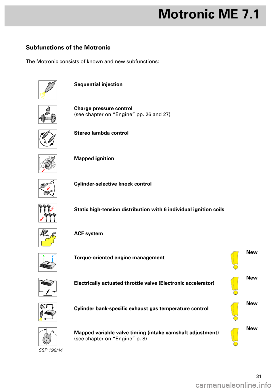
The Motronic consists of known and new subfunctions:
Sequential injection
Charge pressure control
(see chapter on “Engine” pp. 26 and 27)
Stereo lambda control
Mapped ignition
Cylinder-selective knock control
Static high-tension distribution with 6 individual ignition coils
ACF system
Torque-oriented engine management
Electrically actuated throttle valve (Electronic accelerator)
Cylinder bank-specific exhaust gas temperature control
Mapped variable valve timing (intake camshaft adjustment)
(see chapter on “Engine” p. 8)
New
New
New
New
l
SSP 198/44
Page 31 of 72
32
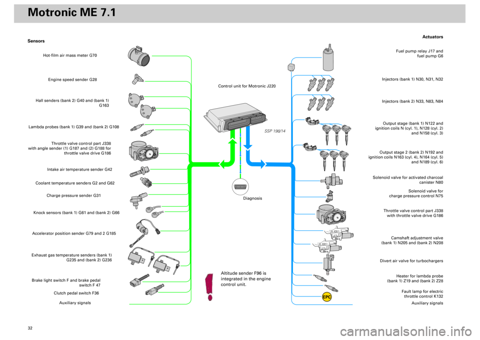
Actuators
Heater for lambda probe
(bank 1) Z19 and (bank 2) Z28
Divert air valve for turbochargers
Camshaft adjustment valve
(bank 1) N205 and (bank 2) N208
Throttle valve control part J338
with throttle valve drive G186
Solenoid valve for
charge pressure control N75
Solenoid valve for activated charcoal
canister N80
Output stage (bank 1) N122 and
ignition coils N (cyl. 1), N128 (cyl. 2)
and N158 (cyl. 3)Injectors (bank 1) N30, N31, N32
Fuel pump relay J17 and
fuel pump G6
Output stage 2 (bank 2) N192 and
ignition coils N163 (cyl. 4), N164 (cyl. 5)
and N189 (cyl. 6)
Fault lamp for electric
throttle control K132
Auxiliary signals
Sensors
Engine speed sender G28
Hall senders (bank 2) G40 and (bank 1)
G163
Lambda probes (bank 1) G39 and (bank 2) G108
Throttle valve control part J338
with angle sender (1) G187 and (2) G188 for
throttle valve drive G186
Intake air temperature sender G42
Coolant temperature senders G2 and G62
Charge pressure sender G31
Knock sensors (bank 1) G61 and (bank 2) G66Accelerator position sender G79 and 2 G185Exhaust gas temperature senders (bank 1)
G235 and (bank 2) G236Brake light switch F and brake pedal
switch F 47
Clutch pedal switch F36
Auxiliary signals
SSP 198/14
EPC
Injectors (bank 2) N33, N83, N84
Hot-film air mass meter G70
Control unit for Motronic J220
Altitude sender F96 is
integrated in the engine
control unit.
Diagnosis
Motronic ME 7.1
Page 32 of 72
33
SSP/198/15
Subsystems of the Motronic
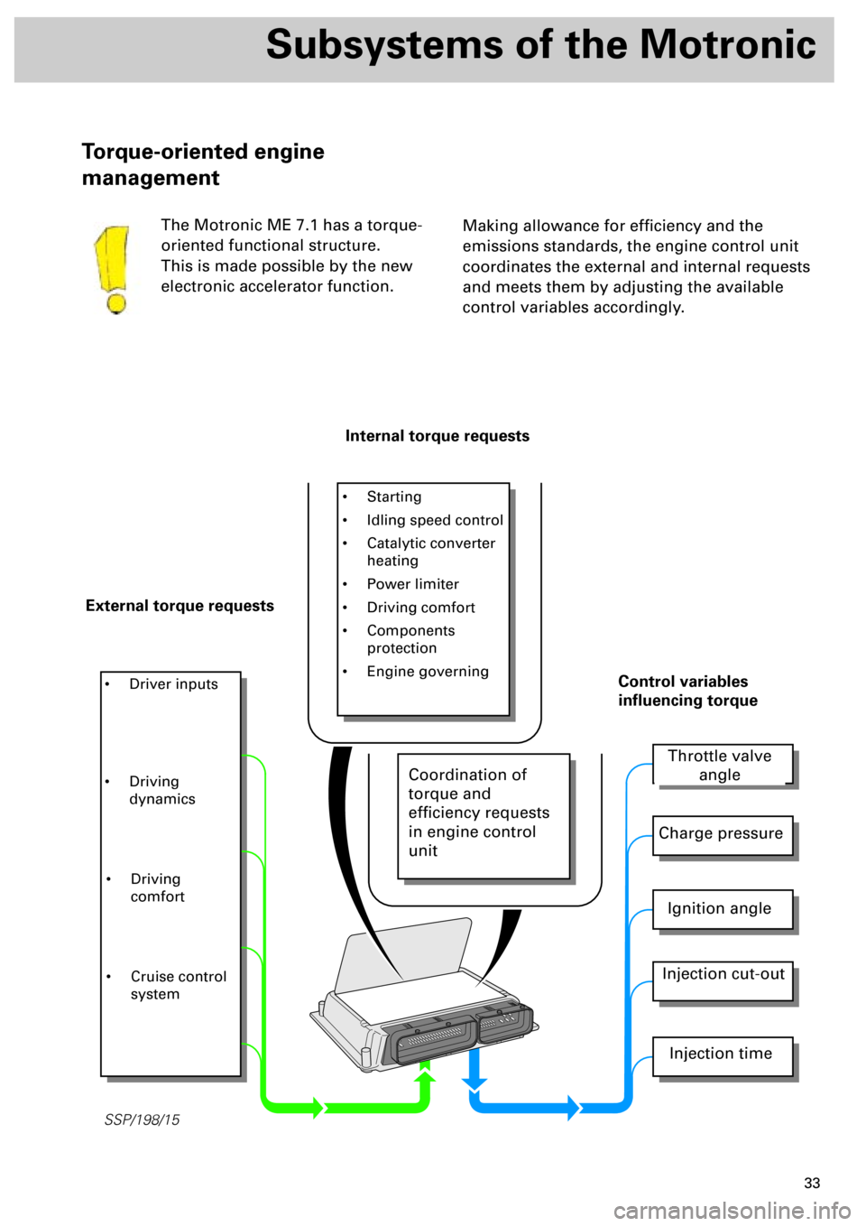
Making allowance for efficiency and the
emissions standards, the engine control unit
coordinates the external and internal requests
and meets them by adjusting the available
control variables accordingly.
Torque-oriented engine
management
The Motronic ME 7.1 has a torque-
oriented functional structure.
This is made possible by the new
electronic accelerator function.
Internal torque requests
External torque requests
• Starting
• Idling speed control
• Catalytic converter
heating
• Power limiter
• Driving comfort
• Components
protection
• Engine governing
• Driver inputs
Throttle valve
angle
Charge pressure
Ignition angle
Injection cut-out
Injection time
Control variables
influencing torque
• Driving
dynamics
• Driving
comfort
• Cruise control
system
Coordination of
torque and
efficiency requests
in engine control
unit
Page 33 of 72
34
Subsystems of the Motronic
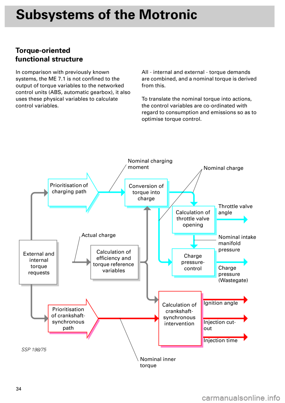
In comparison with previously known
systems, the ME 7.1 is not confined to the
output of torque variables to the networked
control units (ABS, automatic gearbox), it also
uses these physical variables to calculate
control variables.All - internal and external - torque demands
are combined, and a nominal torque is derived
from this.
To translate the nominal torque into actions,
the control variables are co-ordinated with
regard to consumption and emissions so as to
optimise torque control.
SSP 198/75
External and
internal
torque
requests
Calculation of
efficiency and
torque reference
variables
Prioritisation of
charging path
Prioritisation
of crankshaft-
synchronous
path
Conversion of
torque into
charge
Throttle valve
angle
Charge
pressure-
control
Calculation of
crankshaft-
synchronous
intervention
Calculation of
throttle valve
opening
Charge
pressure
(Wastegate)
Ignition angle
Injection cut-
out
Injection time
Nominal charging
moment
Nominal charge
Nominal intake
manifold
pressure
Nominal inner
torque
Actual charge
Torque-oriented
functional structure
Page 34 of 72
35
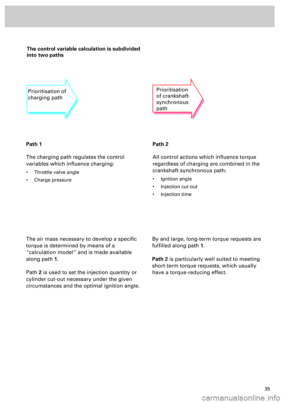
The control variable calculation is subdivided
into two paths
Path 1
The charging path regulates the control
variables which influence charging:
• Throttle valve angle
• Charge pressure
Path 2
All control actions which influence torque
regardless of charging are combined in the
crankshaft-synchronous path:
• Ignition angle
• Injection cut-out
• Injection time
The air mass necessary to develop a specific
torque is determined by means of a
“calculation model“ and is made available
along path
1
.
Path
2
is used to set the injection quantity or
cylinder cut-out necessary under the given
circumstances and the optimal ignition angle.
Prioritisation of
charging pathPrioritisation
of crankshaft-
synchronous
path
By and large, long-term torque requests are
fulfilled along path
1
.
Path 2
is particularly well suited to meeting
short-term torque requests, which usually
have a torque-reducing effect.