AUDI S6 2008 Owners Manual
Manufacturer: AUDI, Model Year: 2008, Model line: S6, Model: AUDI S6 2008Pages: 390, PDF Size: 88.42 MB
Page 351 of 390
_________________________________________________ F_ u_ s_ e_s _ a_n _ d_ b_ u_lb _ s __ ffllll
•
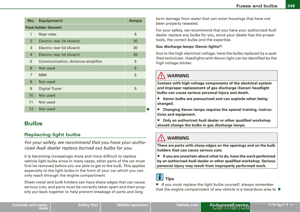
No . Equipment
Fuse holder (brown)
1 R ear vi ew
2 Elect ric rea r lid (Ava nt)
3 Elect ric rea r lid (Avant)
4 Ele ctr ic rea r lid (Ava nt)
5 Communication, Antenna amplifier
6 N ot used
7 M MI
8 Not used
9 Digital Tuner
10 Not u sed
11 Not used
1 2 Not u sed
Bulbs
Replacing light bulbs
Amps
5
30
30
20
5
5
5
5
Fo r yo ur sa fe ty, we rec om mend t hat yo u have your a utho
rize d Audi d ea le r r ep la ce b urned out bul bs fo r you.
It is becoming increasing ly more and more difficult to replace
ve hicle light bu lbs s ince i n many cases, ot her parts of the car mus t
f irst be removed before you are able to get to the bu lb . T his applies
es pecia lly to the ligh t bu lb s in th e fro nt of y our ca r which you can
only reach through the engine compartment .
Sheet meta l and b ulb ho lders can have s harp edge s that can cause
ser ious c uts, and parts must be cor rectl y taken apart a nd t hen p ro p
erly put back together to he lp prevent breakage of parts and long
•
term damage from water that can enter housings that have not
b ee n properly resea led .
For your safety , we recommend that you have your authorized Audi
dea ler replace any bu lbs for you, since your dealer has the proper
t ools, the cor rect bulbs and the expertise.
Gas di scharge lamps (Xenon lights )*:
Due to the high e lectrica l voltage, have the bulbs replaced by a qual
ified technician . H eadlights with Xenon light can be identified by the
high voltage sticker .
& WARNING
Contact with high-voltage components of the ele ctrical system
and imprope r repla cement of gas discharge (Xenon) headlight
bulbs can cause serious personal injury and death.
• Xenon bulbs are pressurized and can explode when being
changed.
• Chang ing Xenon lamps requires the special training , instruc
tions and equipment .
• Only an authorized Audi dealer or other qualified workshop
s hould change the bulbs in ga s di scharge lamps.
& WARNING
The re are parts with sharp edges on the openings and on the bulb
holders that can cause serious cuts.
• If you are uncertain about what to do , have the work performed
by an authorized Audi dealer or other qualified workshop. Serious
per sonal injury may result from improperly performed work .
[ i ] Tips
• I f you must replace the light bu lbs yourself, a lways remember
that the engine compartment of any vehicle is a hazardous area to .,,
Do-it-yourself service
Page 352 of 390
11111.___F_ u_ s _ e_s _ a_n _ d_ b_ u_lb _ s _______________________________________________ _
work in. Always read and heed al l WARNI NGS=> page 289, "Engine
c ompartment" =>& .
• It is best to ask your authorized Audi dealer whenever you need
to change a bulb. •
Page 353 of 390
Emergency situations Ill
-------------=--=----
•
Emergency situations
General
This chapter is intended for trained emergency crews and working
pe rsonnel who have the necessary tools and equ ipment to perform
these operations. •
Starting by pushing or towing
(D Note
You r ve hicle is eq uipped w ith an automatic trans missi on. C o nse
quent ly, the engine cannot be started by pushing or towing .•
Starting with jumper cables
If necess ary, the en gine can b e sta rted by conn ectin g it to
the battery of anothe r vehicle.
If th e engine should fail to start because of a discharged or weak
b at te ry, the batt ery ca n be co nnected t o the ba ttery of another
vehicle, using a
pair of jumper cables to start the engine .
Jumper cables
Use only jumper cables of sufficiently large cross section to carry the
s tarte r curre nt safely. Refer t o the manu fac tu rer 's specif ica tions.
Use only ju mper cabl es with insulated terminal clamps whic h are
distinct ly marked:
plus ( +l cable in mo st cas es c olored red
minus
(- 1 cable in most cases colored black .
& WARNING
Batteries contain electricity, acid , and gas. Any of the se can cause
very ser ious or fatal injury . Follow the instructions below for safe
handling of your vehicle 's battery .
• Always shield your eyes and avoid leaning over the battery
whenever possible .
• A discharged battery can freeze at temperatures just below
32 °F (0 °C l. Before connecting a jumper cable , you must thaw the
frozen battery completely , otherwise it could explode .
• Do not allow battery acid to conta ct eyes or skin. Flush any
contacted area with water immediately.
• Improper use of a booster battery to start a vehicle may cause
an explosion.
• Vehicle batteries generate explosive gases . Keep sparks , flame
and lighted c igarettes away from batteries.
• Do not try to jump start any vehicle with a low acid level in the
battery.
• The voltage of the booster battery must also have a 12-Volt
rating. The capacity (Ah l of the booster battery should not be
lower than that of the discharged battery . Use of batteries of
different voltage or substantially different "Ah" rating may cause
an explosion and personal injury .
• Never charge a frozen battery. Gas trapped in the ice may cause
an explosion.
• Never charge or use a battery that has been frozen . The battery
c ase may have be weakened .
• Use of batter ies of different voltage or substantially different
c apacity (Ah l rating may cause an explosion and injury . The
capacity (Ahl of the booster batte ry should not be lower than that
of the discharged battery. _..
Do-it-yourself service
Page 354 of 390
-Emerg ency situation s PW...__-=---=---------------
& WARN ING (c ontinu ed )
• Bef ore you chec k anything in the engin e compartment , always
re ad and h eed all W ARNINGS =>
page 289, "Engine compa rtment".
0 Note
• Applying a higher voltage booster battery wil l cause expensive
damage to sensitive electronic components, such as contro l units,
relays, radio, e tc.
• There must be no electrical contact between the vehicles as
otherwise current could already start to flow as soon as the positive
( + ) terminals are connected .
[ i ] Tip s
• The discharged battery must be properly connected to the
vehic le's e lectrical system. When jump starting or charging the
battery, never connect the negative ground cable to the battery
negative pos t because the battery manager system must be ab le to
detect the battery's state of charge . Always connect the negative
ground cable to the negat ive ground post of the battery manager
control unit. •
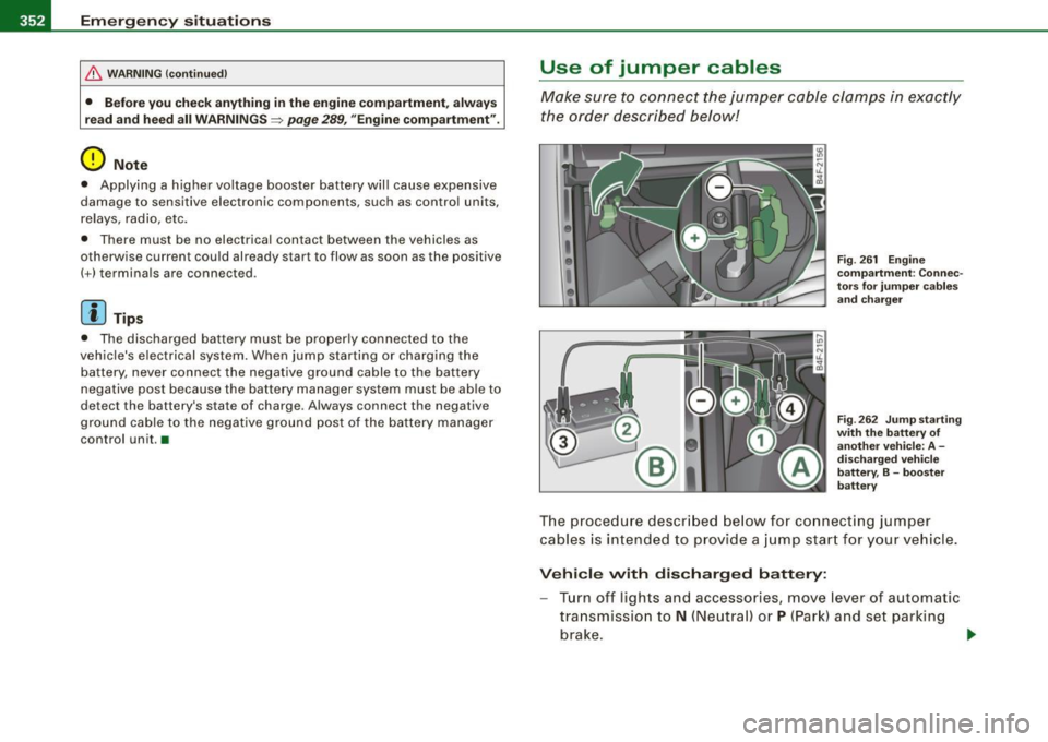
Use of jumper cables
Make sure to connect the jumper c able clamps in exac tly
the order described below!
F ig . 26 1 Engin e
co mpartm ent : Co nnec
to rs for ju mp er ca ble s
and cha rger
F ig . 2 62 Jump starti ng
w ith th e battery of
anot her veh icle: A -
d isc harg ed veh ic le
b att ery, B -boost er
batt ery
The proced ure descr ibed below fo r connecti ng jumper
cables is int ended to prov ide a j ump start f or y our vehicle .
Vehi cle with dis charg ed battery:
- Turn off lights and accessories, move lever of automatic
transmission to
N (Neutral) or P (Par k) and set parking
brake .
~
Page 355 of 390
Emerg ency situ ations -
-------------=--=----
•
Connect POSITIVE (+ ) to PO SITIVE (+ ) (r ed )
- Open the red cover on the pos itive pole => page 352,
fig. 261.
1. Connect one end of the positive cable (red) on the
jump
start bolt=>
page 352, fig. 262 G) (Bolts under red cover
= "positive") of the vehicle to be started @.
2. Connect the other end to the positive terminal@ of the
booster battery ®·
Conn ect NEGATIVE (- ) to NEGATIVE (-) (black )
3. Connect one end to the negat ive termi nal 0 of t he
boos ter battery ®·
4 . Connect the other end of the negative cable (black) to the
jump sta rt bolt 0 (Bolts with hex head = "n egative") of
the vehicle to be s tarted @.
Startin g th e e ngin e
-Start the engine of the veh icle w ith the booster battery .
Run t he engine at a moderate speed .
- Start engine with discharged ve hicle battery in the usual
ma nner.
- If the engine fails to s tart: do not keep the star ter
cranking for longer than 10 seconds. Wait for about
30 seconds and then try again.
- With engine running, remove jumper cables from both
vehicles in the exact reverse order.
- Close the red cover on the positive pole.
The battery is vented to the outside to prevent gases from entering
the vehic le interior . Make sure that the jumper clamps are well connected with their
metal parts in full contact with the battery
t erminals .
& WARNING
To avoid seriou s per sonal in jur y a nd d amage to the vehicle , heed
a ll wa rning s and in stru ction s o f th e jum per ca ble man ufa cturer . If
in doubt , call for ro ad serv ice.
• Jump er c abl es m ust b e lo ng eno ugh so that the vehi cle s d o not
touch .
• When conne cting jumpe r cable s, ma ke sure th at the y cann ot
g et caught in an y mo ving p arts i n the engine comp art m ent .
• Before you che ck anyth ing in the en gin e com partm ent , a lwa ys
r ea d and h eed all W ARNIN GS~ pag e
289, "Engine compa rtm ent ".
0 Note
Improper hook -up of jumper cables can ruin the generato r.
• Always connect POSITIVE(+) to POS ITIVE( +), and NEGATIVE( -) to
NEGATIVE( -) ground post of the battery manager control unit.
• Check that al l screw p lugs on the battery ce lls are screwed in
firm ly . If not, tighten plugs prior to connecting clamp on negative
battery termi nal.
• Please note that the procedure for connecting a jumper cab le as
described above applies specifical ly to the case of your vehicle
being jump started. When you are giving a jump start to another
vehicle, do not connect the negative(-) cable to the negative (-1
terminal on the discharged battery©~ page 352, fig. 262. Instead,
securely connect the negative ( -1 cable to either a solid metal
component that is firmly bolted to the engine b lock or to the engine
block itself . If the battery that is being charged does not vent to the
outside, escap ing battery gas could ignite and exp lode! •
Do-it-yourself service
Page 356 of 390
IIIII...__E_ m _ e _r.;:g '-e_ n_ c-=y - s_ i_t _u _a _t_ i_o _n_ s _______________________________________________ _
Emergency towing with commercial
tow truck
General hints
Your Audi requires special handling for towing.
The following information is to be used by commercial tow truck
operators who know how to operate their equipment safely.
• Never tow your Audi, towing will cause damage to the engine
and transmission.
• Never wrap the safety chains or winch cables around the brake
lines.
• To prevent unnecessary damage, your Audi must be transported
with a flat bed truck.
• To load the vehicle on to the flat bed, use the towing loop found
in the vehicle tools and attach to the front or rear anchorage
~ page 354 and~ page 355.
& WARNING
A vehicle being towed is not safe for passengers. Never allow
anyone to ride in a vehicle being towed, for any reason. •
Front towing loop
Do not install the front towing loop until it is needed.
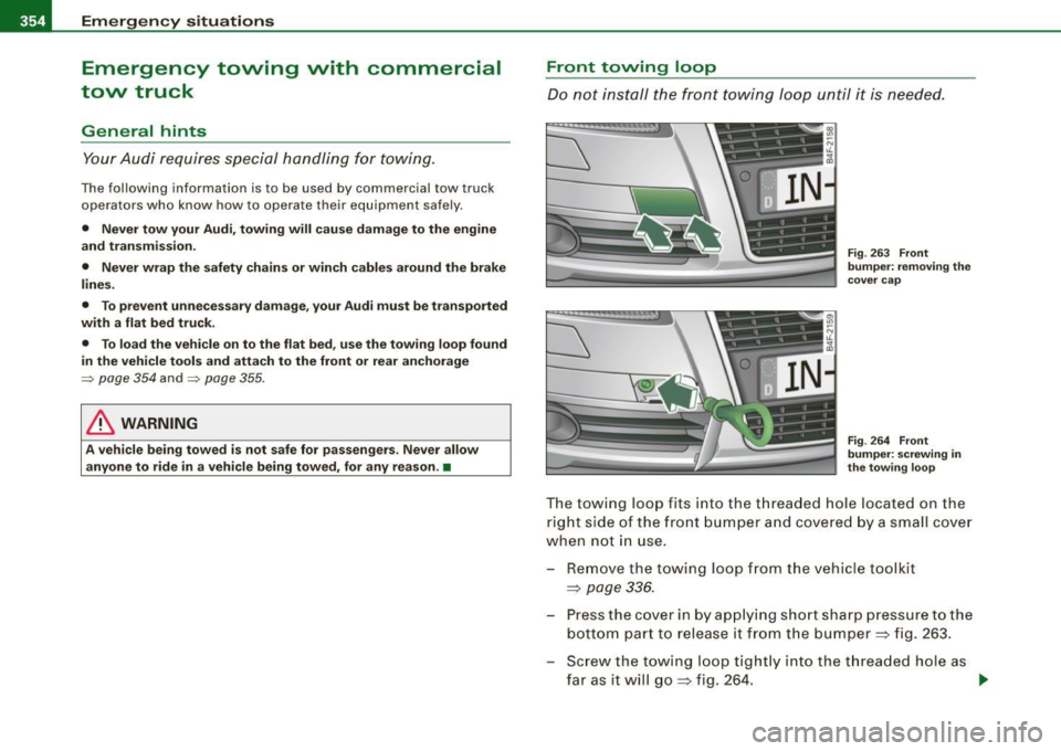
Fig. 263 Front
bumper: removing the
cover cap
Fig . 264 Front
bumper: screwing in
the towing loop
The towing loop fits into the threaded hole located on the
right side of the front bumper and covered by a small cover
when not in use.
- Remove the towing loop from the vehicle toolkit
=>
page 336.
- Press the cover in by applying short sharp pressure to the
bottom part to release it from the bumper => fig. 263.
- Screw the towing loop tightly into the threaded hole as
far as it will go=> fig. 264. ..,
Page 357 of 390
Emergency situations -
----------------=-~----
When it is no longer needed, unscrew the towing loop and put it
back into the vehicle toolkit. Be sure to have the towing loop stored
in the vehicle at all times.
& WARNING
If the towing loop is not screwed in as far as it will go, the thread
can pull out when the vehicle is towed -potential risk of an
accident. •
Rear towing loop
Do not install the rear towing loop until it is needed.
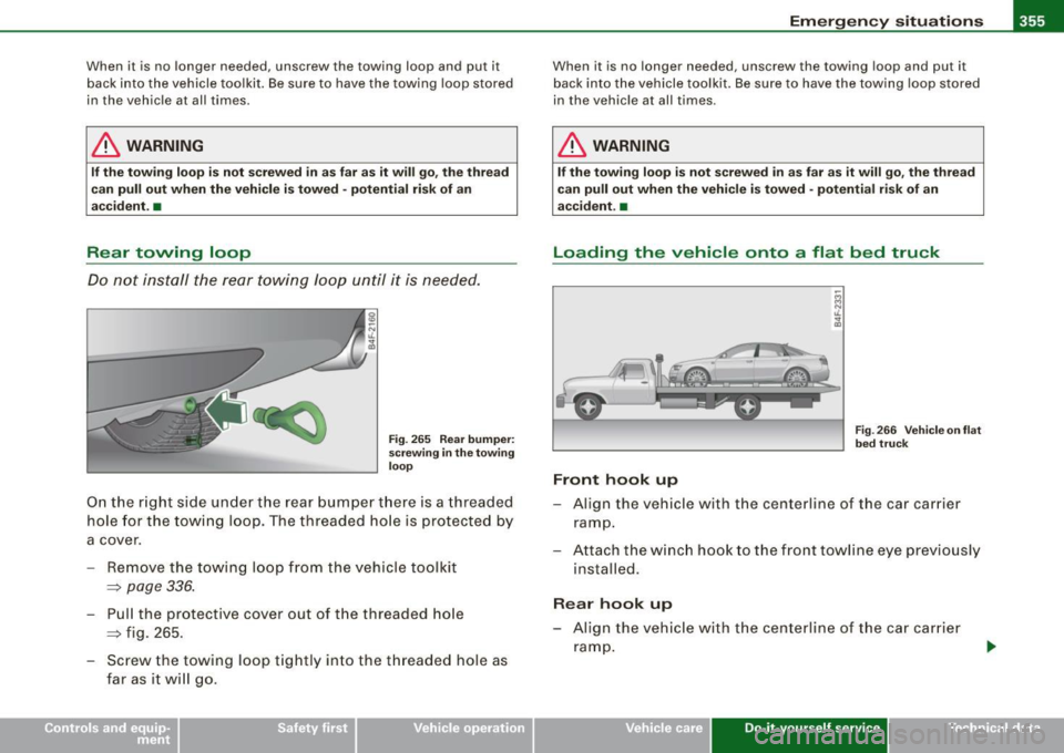
Fig. 265 Rear bumper:
screwing in the towing
loop
On the right side under the rear bumper there is a threaded
hole for the towing loop. The threaded hole is protected by
a cover.
- Remove the towing loop from the vehicle toolkit
=> page 336.
- Pull the protective cover out of the threaded hole
~ fig. 265 .
- Screw the towing loop tightly into the threaded hole as far as it will go .
When it is no longer needed, unscrew the towing loop and put it
back into the vehicle toolkit. Be sure to have the towing loop stored
in the vehicle at all times.
& WARNING
If the towing loop is not screwed in as far as it will go, the thread
can pull out when the vehicle is towed -potential risk of an
accident. •
Loading the vehicle onto a flat bed truck
Front hook up
Fig. 266 Vehicle on flat
bed truck
- Align the vehicle with the centerline of the car carrier
ramp.
- Attach the winch hook to the front towline eye previously
installed .
Rear hook up
-Align the vehicle with the centerline of the car carrier
ramp.
Vehicle care Do-it-yourself service irechnical data
Page 358 of 390
IIIII...__E_ m _ e _r.;:g '-e_ n_ c-=y - s_ i_t _u _a _t_ i_o _n_ s _______________________________________________ _
- Attach the winch hook to the rear towline eye previously
installed.
[ i ) Tips
Check carefully to make sure the hook -up is secure before moving
the ca r up the flatbed t ruck ramp. •
Lifting vehicle
Lifting with workshop hoist and with floor
jack
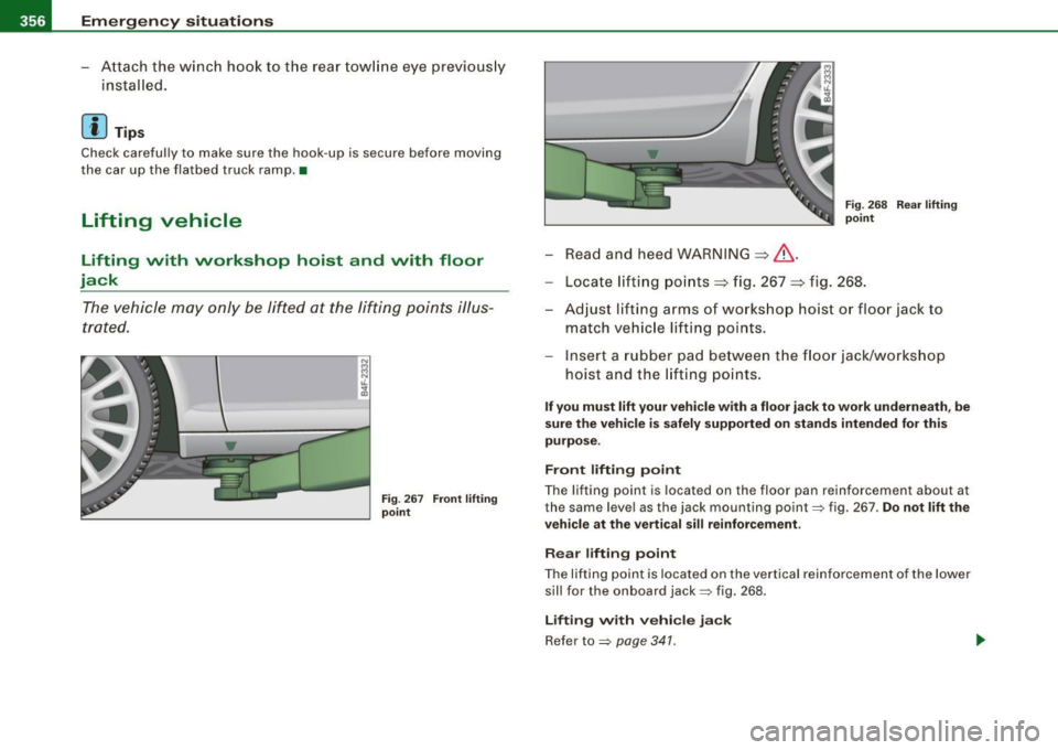
The vehicle may only be lifted at the lifting points illus
trated.
Fig . 267 Front lifting
point
- Read and heed WARNING::::,& .
Fig. 268 Rear lifting
point
- Locate lifting points::::, fig. 267 ::::, fig. 268.
- Adjust lifting arms of workshop hoist or floor jack to
match vehicle lifting points.
- Insert a rubber pad between the floor jack/workshop
hoist and the lifting points.
If you must lift your vehicle with a floor jack to work underneath, be
sure the vehicle is safely supported on stands intended for this
purpose.
Front lifting point
The lifting point is located on the floor pan reinforcement about at
the same level as the jack mounting point:::::, fig. 267 .
Do not lift the
vehicle at the vertical sill reinforcement.
Rear lifting point
The lifting point is located on the vertical reinforcement of the lower
sill for the on board jack:::::, fig. 268.
Lifting with vehicle jack
Refer to :::::, page 341 .
Page 359 of 390
________________________________________________ E _m_ e_r.:g :;,. e_ n_c ...: y:.- s_ i_ t _u _a_ t_ i_ o _ n_ s __ lll
•
& WARNING
• To reduce the risk of serious injury and vehicle damage.
-Always lift the vehicle only at the special workshop hoist and
floor jack lift points illustrated
=> page 356, fig. 267 and
=> page 356, fig. 268.
- Failure to lift the vehicle at these points could cause the
vehicle to tilt or fall from a lift if there is a change in vehicle
weight distribution and balance. This might happen, for
example, when heavy components such as the engine block or
transmission are removed.
• When removing heavy components like these, anchor vehicle
to hoist or add corresponding weights to maintain the center of
gravity. Otherwise, the vehicle might tilt or slip off the hoist,
causing serious personal injury.
0 Note
• Be aware of the following points before lifting the vehicle:
- The vehicle should never be lifted or jacked up from under
neath the engine oil pan, the transmission housing, the front or
rear axle or the body side members . This could lead to serious
damage.
- To avoid damage to the underbody or chassis frame, a rubber
pad must be inserted between the floor jack and the lift points.
- Before driving over a workshop hoist, check that the vehicle
weight does not exceed the permissible lifting capacity of the hoist .
- Before driving over a workshop hoist, ensure that there is
sufficient clearance between the hoist and low parts of the
vehicle. •
Do-it-yourself service
Page 360 of 390

-c-
_,