AUDI S6 2010 Owners Manual
Manufacturer: AUDI, Model Year: 2010, Model line: S6, Model: AUDI S6 2010Pages: 368, PDF Size: 86.82 MB
Page 321 of 368

_____________________________________________ W __ h_a_ t_ d_o_ I_ d_o _ n_ o_ w _ ? __ _
& WARN ING (con tinued)
Trans missio n in "P " (Pa rk) w ill not pre ve nt the vehicle from
mo ving .
• Befo re you ch an ge a wheel , be s ure the ground i s le ve l an d
firm . If ne cess ary, us e a sturdy b oard und er the jack.
• Aft er in st a llin g the sp are wheel , make sure that you repl ace
the flat tire /wheel in it s storage area prop erly and tight en the
knurled ret ain ing s crew se cu rel y.•
Changing a wheel
When you change a wheel, follow the sequence described
below step-by-step and in exactly that order .
1. Activate the vehicle jack mode (only vehicles with Adaptive
Air Suspension) =>
page 168.
2. Remove the decorative wheel cover *. For more details see
also =>
page 320, "Decorative wheel covers" .
3 . Loosen the
wheel bolts => page 320.
4. Locate the proper mo unti ng point for the jack and align
the jack below that point=>
page 321.
5. Lift the car with the jack => page 321.
6. Remove the wheel with the flat tire and then install the
spare =>
page 322.
7. Tighten all wheel bolts lightly.
8 .
Lower the vehicle with the jack.
9. Use the wheel bolt wrench and
firmly t ighten all wheel
bolts =>
page 320.
10. Replace the decorative wheel cover *.
Safety first
1 1. Deactivate the vehicle jack mode (only vehicles with
Adaptive Air Suspens ion)=>
page 168 .
& WARNING
Alwa ys re ad and f ollow all WARNINGS and information ~ & in
" Ra ising the vehicl e" on pag e
321 and ~ pag e 323. •
After changing a wheel
A wheel change is not complete without the doing the
following .
-Store and secure the wheel you replaced in the spare
wheel well .
- Replace the tools and the jack in the ir proper location.
- Check the tir e pr essur e on the spare wheel immediately
after mounting it .
- As soon as possib le, have the
tighten ing torques on a ll
wheel bolts checked with a torque wrench . The correct
tightening torque is 90 ft lb (120 Nm) .
- Have the flat tire
replaced as soon as possible.
[ i ] Tips
• If you not ic e that the wheel bolts are corroded and difficu lt to turn
wh ile chang ing a tire, they should be replaced before you check the
tightening torque .
• Drive at reduced speed until you have the tighten ing torques
checked. •
Vehicle care Do-it-yourself service Technical data
Page 322 of 368

lffl!IL--....:..:W:..:..; h:..:.:: a:..:t :... d.:.:..: o:.:...:. I..;d:.:...:. o....:..: n:..:o :...w:..:..:. ? ___________________________________________ _
Applies to veh icles : w ith deco rat ive wheel covers
Decorative wheel covers
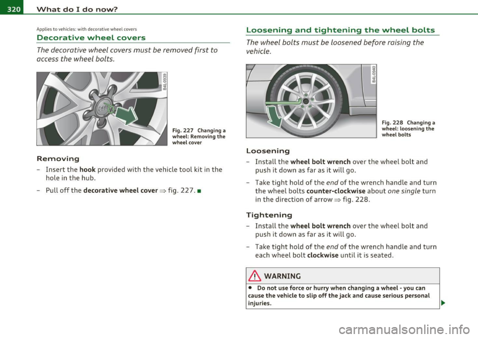
The decorative wheel covers must be removed first to
access the wheel bolts .
Removing
Fig. 227 Changing a
wheel: Removing the
wheel cover
-Insert the hook provided with the vehicle tool kit in the
hole in the hub .
- Pull off the
decorative wheel cover => fig . 2 2 7. •
Loosening and tightening the wheel bolts
The wheel bolts must be loosened before raising the
vehicle.
Loosening
Fig. 228 Changing a
wheel: loosening the
wheel bolts
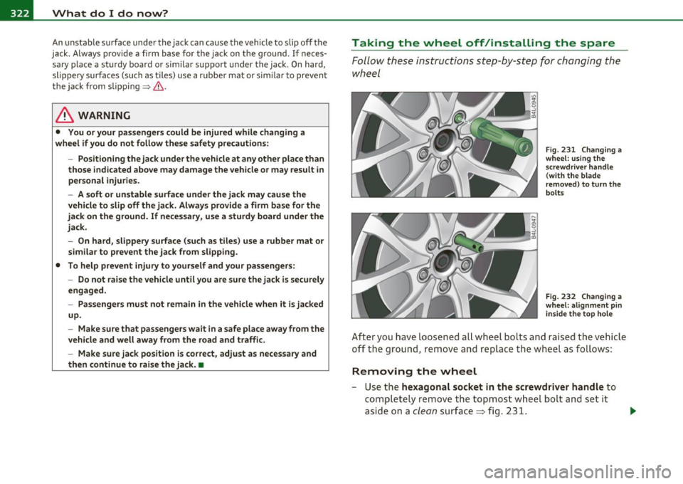
-Install the wheel bolt wrench over the wheel bolt and
push it down as far as it will go.
- Take tight hold of the
end of the wrench handle and turn
the wheel bolts
counter-clockwise about one single turn
in the direction of arrow=> fig . 228.
Tightening
- Install the wheel bolt wrench over the wheel bolt and
push it down as far as it will go.
- Take tight hold of the
end of the wrench handle and turn
each wheel bolt
clockwise until it is seated.
& WARNING
• Do not use force or hurry when changing a wheel -you can
cause the vehicle to slip off the jack and cause serious personal
injuries.
Page 323 of 368

What do I do now? -
------------------
& WARNING (continued)
• Do not loosen the wheel bolts more than one turn before you
raise the vehicle with the jack. -You risk an injury.
(I) Tips
• Never use the hexagonal socket in the handle of the screwdriver to
loosen o r tighten the wheel bolts .
• If a wheel bolt is very tight, you may find it easier to loosen by
carefully pushing down on the end of th e wheel bolt wrench with
one
foot only .
As you do so, hold on to the car to keep your balance and
take ca re not to slip .•
Raising the vehicle
The vehicle must be li~ed with the jack first before the
wheel can be removed.
Fig. 229 Changing a
wheel: mounting
points for the jack
Vehicle OP-eration
Fig. 230 Close-up:
proper positioning of
jack
- Activate the vehicle jack mode* (only vehicles with Adap
tive Air Suspension)=>
page 168.
-Engage the parking brake to prevent your vehicle from
rolling unintentionally.
- Move the
selector lever to position P.
-Position the jack below the door sill under the mounting
point
that is closest to the wheel to be changed
=> fig . 229.
- Extend the
jack under the lifting point on the door sill until
its arm is positioned directly under the lifting point=>& .
- Align the jack so that its arm©=> fig. 230 engages in the
designated lifting point in the door sill and the movable
base ® lies flat on the ground. The base® must be
vertical under the lifting point@.
- Wind the jack up further until the flat tire comes off the
ground =>& .
The jack must be installed only at the places indicated=> fig . 229.
There is exactly
one location for each wheel. The jack must not be
positioned at any other location
~ & .
Vehicle care Do-it-yourself service iTechnical data
Page 324 of 368

-What do I do now? .,,,.,__ ______________ _
An unstable surface under the jack can cause the vehicle to slip off the
jack. Always provide a firm base for the jack on the ground .
If neces
sary place a sturdy board or similar support under the jack. On hard,
slippery surfaces (such as tiles) use a rubber mat or similar to prevent
the jack from slipping=> &.
& WARNING
• You or your passengers could be injured while changing a
wheel if you do not follow these safety precautions:
-Positioning the jack under the vehicle at any other place than
those indicated above may damage the vehicle or may result in
personal injuries.
- A soft or unstable surface under the jack may cause the
vehicle to slip off the jack. Always provide a firm base for the
jack on the ground. If necessary, use a sturdy board under the
jack.
- On hard, slippery surface (such as tiles) use a rubber mat or
similar to prevent the jack from slipping.
• To help prevent injury to yourself and your passengers:
- Do not raise the vehicle until you are sure the jack is securely
engaged.
- Passengers must not remain in the vehicle when it is jacked
up.
- Make sure that passengers wait
in a safe place away from the
vehicle and well away from the road and traffic.
- Make sure jack position is correct, adjust as necessary and
then continue to raise the jack. •
Taking the wheel off/installing the spare
Follow these instructions step-by -step for changing the
wheel
Fig. 231 Changing a
wheel: using the
screwdriver handle
(with the blade
removed) to turn the
bolts
Fig. 232 Changing a
wheel: alignment pin inside the top hole
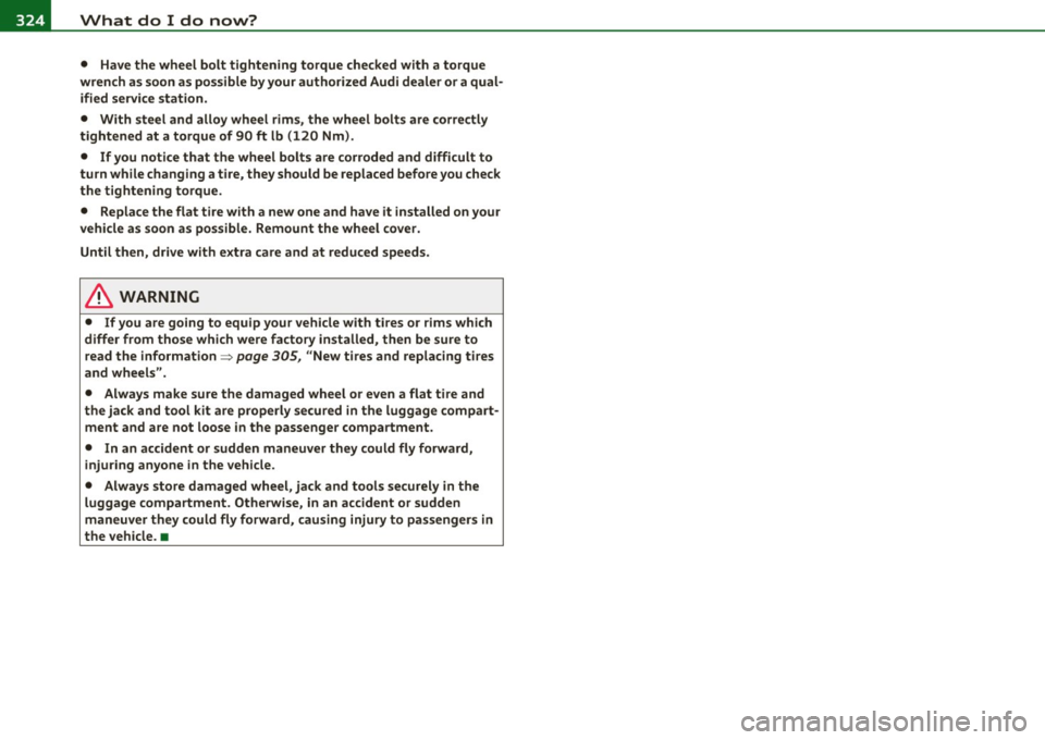
After you have loosened all wheel bolts and raised the vehicle
off the ground, remove and replace the wheel as follows:
Removing the wheel
- Use the hexagonal socket in the screwdriver handle to
completely remove the topmost wheel bolt and set it
aside on a
clean surface => fig. 231.
Page 325 of 368

What do I do now? -________________ PfWII
- Screw the threaded end of the alignment pin from the
tool kit hand-tight into the empty bo lt hole~
page 322,
fig. 232.
- Then re m ove the o ther wheel bolts as described above.
- Take off t he w heel leaving the alignment pin i n the bolt
hole.
Putting on the spare wheel
- Lift the spare wheel and carefully slide it over the alig n
ment pi n to guide it in p lace .
- Use the hexagona l socket in the screwdriver handle to
screw in and tighte n all w heel bolts
slightly.
- Remove the alig nment pi n and inse rt an d tighten the
remaining wheel bolt slig htly like the rest.
- Turn the jac k han dle counter-c lockwise to lower the
ve hicle u ntil the jack is fully released.
- Use the wheel bolt wrench to t ighten all whee l bolts firmly
~ page 320 . Tighten them crosswise, from one bolt to
the (approximately) opposite one, to keep the w heel
centered.
[I] Tips
Never use the hexagonal socket i n the handle of the screwdriver to
loosen or tighten the wheel bolts.
• Pull the reve rsible blade from the screwdriver before yo u use the
hexagonal socket in the handle to t urn the whee l bolts.
• When mounting tires with
unidirectional tread design make sure
t he tread pa ttern is po inted the right way~
page 323.
Safety first
• The wheel bolts should be clea n and easy to turn. Check for dirt
and cor rosion on the mat ing surfa ces o f bo th the whee l and the hub.
Remove all d irt from these surfaces before remounting the wheel. •
Tires with unidirectional tread design
Tires with unidirectional tread design must be mounted
with their trea d pattern pointed in the right direction .
Using a spare tire with a tread pattern intended for
use in a specific direction
When using a spare tire w ith a tread pattern intended for use in a
specific direction, p lease note the fo llow ing:
• T he direct ion of rotation is marked by an ar row on the s ide of the
tire.
• If the spare tire has to be installed in the incor rect d irect ion, use
the spare tire only tempo rari ly since the tire wi ll not be ab le to
achieve its optimum pe rforma nce charact erist ics with rega rd to
aquaplaning, noise and wear.
• We recommend that you pay particular attention to this fact
during wet weather and that you adjust your speed to match road
condit ions.
• Replace the flat t ire with a new one and have it installed on your
vehicle as soon as possible to restore the handling advantages of a
unidirect iona l tire .•
Notes on wheel changing
Please read the information~ page 305, "New tires and replacing
t ires and wheels" if yo u are go ing to use a spa re t ire wh ich is d iffe rent
from the tires on yo ur vehicle .
After you c hange a ti re:
• Check the tire pressure on the spa re immediately after installa-
tion. ..,
Vehicle care Do-it-yourself service Technical data
Page 326 of 368

lffll.___W __ h_a_ t_ d_ o_ I_ d_o_ n_ o_w _ ? _____________________________________________ _
• Have the wheel bolt tightening torque checked with a torque
wrench as soon as possible by your authorized Audi dealer or a qual ified service station.
• With steel and alloy wheel rims, the wheel bolts are correctly
tightened at a torque of 90
ft lb (120 Nm).
• If you notice that the wheel bolts are corroded and difficult to
turn while changing a tire, they should be replaced before you check
the tightening torque.
• Replace the flat tire with a new one and have it installed on your
vehicle as soon as possible. Remount the wheel cover.
Until then, drive with extra care and at reduced speeds.
& WARNING
• If you are going to equip your vehicle with tires or rims which
differ from those which were factory installed, then be sure to
read the information =>
page 305, "New tires and replacing tires
and wheels".
• Always make sure the damaged wheel or even a flat tire and
the jack and tool kit are properly secured in the luggage compart
ment and are not loose in the passenger compartment.
• In an accident or sudden maneuver they could fly forward,
injuring anyone in the vehicle.
• Always store damaged wheel, jack and tools securely in the
luggage compartment. Otherwise, in an accident or sudden
maneuver they could fly forward, causing injury to passengers in
the vehicle. •
Page 327 of 368

Fuses and bulbs -_______________ __.PfWII
Fuses and bulbs
Fuses
Replacing a fuse
A problem in the electrical system may be caused by a
blown fuse.
Fig. 233 Instrument
panel left: Face cover
Fig. 234 Instrument
panel left: Content
Face cover
-Locate the fuse which belongs to the component which
failed.
- Switch off the ignition and the electrical component
affected.
Vehicle OP-eration
- Carefully pry the face cover off the instrument panel using
the ignition key or a screwdriver::::::, fig. 233.
- Remove the plastic clip @from its retainer in the face
cover==> fig. 234, place it over the questionable fuse and
remove the fuse.
- Replace a blown fuse (recognizable by the melted metal
strip inside) with a fuse of the
same amperage.
The individual circuits are protected by fuses. The fuse panels with
the fuses are located on the left and right front faces of the instru
ment panel behind a cover and in the right storage area in the
luggage compartment.
Ther e is a plastic clip@ in the cover on the left side of the instrument
panel, which can be used to remove the fuses. The crank @ is used for
eme rgency operation of the power roof*. You will also find a label on
both covers in the instrument panel with the fuse layout © for the
corresponding fuse panel.
& WARNING
Never replace a fuse with one that has a higher amperage rating.
• A fuse with a too high amperage could damage the electrical
part and cause a fire.
0 Note
• On no account should fuses be repaired (e.g. patched up with tin
foil or wire) as this may cause serious damage elsewhere in the elec
trical circuit or cause fire.
• If a fuse blows repeatedly, do not keep replacing it. Instead, have
the cause of the repeated short circuit or overload located and fixed.
ti>
Vehicle care Do-it-yourself service iTechnical data
Page 328 of 368

m.___F_ u_ s_e _s _ a _ n_d_ b_ u_ lb_ s _____________________________________________ _
(I) Tips
You are well advised to keep a supply of spare fuses in your vehicle .
Fuses with the proper ampere ratings are available at your Audi
dealer. •
Fuse Location, Instrument Panel left
Fig. 23S Fuse pan el
layout
Some of the equipment items listed a re optiona l or only avai lable on
certain mode l configurat ions.
Note that the following t able i s accu rate at the time of going to
pre ss and is subject to change. In the event of discrepancies, the
label on the in side of the cover alwa ys takes precedence.
T he power seats are p rotected by circuit br eaker s, which a utomat i
cally reset after a few seconds after the overload has been remedied .
No. Equipment
1 Not use d
2 Not used
3 Eng ine management
4 Oil level sensor
Amps
s
5
..
No . Equipment
5
6
7
8
9
10
11
12
1 3
14
1 5
16
17
18
1 9
20
21
22
23
24
25
26
27
28
Climate control, tire pressure mon itoring sys
tem
Electronic Stabilization Program (ESP), clutch
sensor
Di agnost ic co nnector
Homelink control unit
A utom atic dimming in ter ior m irr or
Adaptive Cruise Control
Not used
Diagnostic connector
Sw itch module stee ring col umn
Not used
I ns trumen t cluste r, contro l modu le Gatew ay
Telephone, cell phone Elect ronic Stabilization Program (ESP)
Headlight electronics, left-side
Ra in s ensor
Heated washer nozzles
Se at adjus tment ( drive r)
MMI display
Electromec hanical park ing brake
Not used
N ot used
No t used
No t used
Not used
Amps
5
5
5
5
5
5
10
10
10
5
10
5
5
5
1 0
5
5
-
Page 329 of 368

______________________________________________ F _u_s _e_ s_ a_ n_ d _ b _u_l_b _ s _ ___.9I
No. Equipment
29 Not used
30 Not used
31 Back-up
light switch, transmission, engine com-
ponents
Intelligent power module driver (footwell light
32 and front headlights, horn, wiper system, elec-
trically adjustable steering wheel)
-
33 Intelligent power module dr
iver
(lights left-side)
34 Intelligent power module driver
(lights right-side)
35 Not used
36 Headlight
washer system
37 Electronic Stabilization Program (ESP)
38 Wiper system
39 Door control module
left-side
Horn
41 Heater fan
42 Control module electronic ignition lock/electri-
cally adjustable steering wheel
43 Rear
windshie ld wiper (Avant)
44 Power window opener (left-side)
Amps
15
30
25
25
30
25
30 15
25
40
30
15
-
-
35 •
Vehicle OP-eration
Fuse Location, Instrument Panel right
Fig. 236 Fuse panel
l ayou t
Some of the equipment items listed are optional or only available on
certain model configurations.
Note that the following table is accurate at the time of going to
press and is subject to change. In the event of discrepancies, the
label on the inside of the cover always takes precedence.
The power seats are protected by circuit breakers , which automati
cally reset afte r a few seconds after the overload has been remedied.
No. Equipment Amps
Fuse holder (black)
1 Control module Convenience
key
15
2 Cigarette lighter front 20
3 Tire pressure monitoring system
5
4 Electrical outlet front (center console)
20
-
5 Intelligent power module passenger
15
(glove box lock)
6 Door control module right-s ide
15
Sunroof 20
A/C controls 10
Vehicle care Do-it-yourself service iTechnical data
Page 330 of 368

.,.,___F_ u_ s_e _ s_ a_n_ d_ b_u _ l_ b_ s _______________________________________________ _
No. Equipment Amps
9 Heated seats, front 30
10 MMI
7,5
11 Seat adjustment (passenger) 10
12 Communication 5
Fuse holder (brown)
1 Electric fuel pump 20/30
2 Adaptive Air Suspension
15
3 Lane assist 10
4 Audi side assist
5
5 Adaptive Air Suspension 5
6 Shift gate automatic transmission/clutch switch 5
7 Parking System 5
8 Control module Gateway 5
9
Automatic headlight range control (auxiliary 5
driving lights), headlight electronics, right-side
10 Airbag 5
11 Heated rear seats 5
12 Telephone
5 •
Fuse Location, Luggage Compartment
right
Fig. 237 Fuse panel
layout
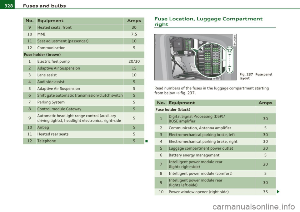
Read numbers of the fuses in the luggage compartment starting
from below :::::> fig. 23 7.
No. Equipment
Amps
Fuse holder (black)
1 Digital Signal Processing (DSP)/ 30 BOSE amplifier
2 Communication, Antenna amplifier 5
3 Electromechanical parking brake, left 30
4 Electromechanical parking brake, right
30
5 Luggage compartment power outlet
20
6 Battery energy management 5
7 Intelligent power module rear
20 (lights right-side)
8 Intelligent power module (comfort)
5
9 Intelligent power module rear
30
(lights left-side)
10 Power window opener (right-side)
35
-
-
-
...