display AUDI S8 2010 Owners Manual
[x] Cancel search | Manufacturer: AUDI, Model Year: 2010, Model line: S8, Model: AUDI S8 2010Pages: 384, PDF Size: 90.95 MB
Page 4 of 384
Table of contents
Table of contents
Vehicle literature
About this Owner's Manual ............. ...... .
Controls and
equipment .............. .
Instruments and controls ... .
General illustration ........... .
Instruments and
warning/indicator Lights ..... .
Instruments ................ .
Warning/indicator ligh ts ...... .
Driver information display ... .
Introduction ............ ... . .
On-Board Diagno stic system
(OBD) ....................... .
Auto Ch eck Control ........... .
Speed warning system ........ .
Tr ip computer ............... .
Opening and closing ......... .
Keys ........................ .
Power locking system ........ .
Rear lid/Trunk lid ......... ... .
Child safety Lock ............. .
Convenience key ............. .
Anti-theft alarm system ...... .
Power windows .............. .
Sliding/tilting power sunroof .. .
Clear vision .. ................ .
Lights ....... ......... ...... .
Interior ligh ts ........ ....... .
5
6
8
9
9
10
10
14
22
22
25
26
35
36
39
39
41
46
49
so
52
53
57
60
60
65 Vi
sion
Wiper and washer system
Mirrors
Seats and storage ........... .
General recommendations .... .
Power seat ....... ........... .
Head restraint s .... .......... .
Armr est ................. ... .
Seat memory ................ .
Rear seats ............. ..... .
Indiv idual rear seats ......... .
Luggage compartment .. ..... .
Roof rack ................... .
Cupho lder .................. .
Ashtray ..................... .
Cigarette Lighter/socket ...... .
Long cente r console .... ...... .
Storage ............. ....... .
Warm and cold ........... ... .
Climat e controls ...... ... .. .. .
W ind shield defogging/defrosting
Rear climate controls ........ .
Basic settin gs ............... .
On the road ................. .
s . teenng .................... .
I gn ition lock and ign ition switch
S tarti ng and stopping the en gine
Starting and stopping the engine
us ing the Convenience ke y .....
Electromechanical park ing brake
C ru ise control ............... . 68
70
7
4
76
76
77
81
83
8 4
85
87
90
92
9 4
96
97
98
98
103
103
112
114
115
11 7
11 7
118
119
120
123
126
Adaptive Cruise Control ....... 128
Speed and distance control
system
Driver information .......... .. .
System Limitation s ........... .
A d' l . u I ane assist ............. . .
128
135
139
142
Lane assist . . . . . . . . . . . . . . . . . . . 142
Audi side assist ............... 145
Lane Change Assistan t . . . . . . . . . 145
No tes ..... ......... .......... 152
Automatic transmission 154
tiptronic ® (6-speed automatic
transmission ) . . . . . . . . . . . . . . . . . 1 54
Advanced Parking System ..... 161
Advanced Parking System with
rear view camera .............. 161
Specia l park ing situat ions . . . . . . 169
Tow ing hitch ........... ....... 1 71
Settings in the MMI ......... ... 171
Saf ety tips .... ................ 173
Adaptive Air Suspension 176
Adaptiv e Air Suspens ion and
Damp ing . . . . . . . . . . . . . . . . . . . . . 176
Homelink ® ............. ...... 181
Universal remote control
181
Safety first ............... 186
Driving Safely ................. 186
General notes . . . . . . . . . . . . . . . . . 186
Proper occupan t seating
positions . . . . . . . . . . . . . . . . . . . . . 188
Driver and passenger side
footwell . . . . . . . . . . . . . . . . . . . . . . 192
Page 8 of 384
About this Owner's Manual
About this Owner's Manual
This owner's manual contains important information, tips, sugges
tions, and warnings for the use of your vehicle.
Make sure that this owner's manual is always located in the veh icle.
This is especia lly important if you allow other people to drive the
vehicle, or if you sell it.
This owner's manual describes the
equipment range specified for
this model at the editorial deadline date. Some of the equipment
described here will only be available at a later date, or only in specific
markets.
Some sections in this owner's manual do not apply to all vehicles. In
that case, the
range of applicability is given at the beginning of the
section, e. g. "Appl ies to vehicles: with Advanced Parking System". In
addition, optional equ ipment is indicated by an asterisk"*".
Th e detai ls in the
illustrations may be different from those in your
vehicle, and are intended to be viewed as a basic gu ide.
You will find a
table of contents at the beginning of this book, which
displays all topics described in this manua l in order of appearance.
You will find an alphabetical
index at the end of this book.
All
directions , such as "left", "right", "front", "back", are relative to
the direction of travel.
* optional equipment
.,. This section continues on the next page.
a Indicates the end of a section.
® Registered trademarks are identified with a®. If this symbol is
missing, it is no guarantee that the terms can be used freely.
=> &. Cross-reference to a "WARNING!" within a sect ion. For indica
tion with a page number, the corresponding "WARN ING!" can be
found outs ide of the section .
& WARNING
Text with this symbol contains important information on safety
and how to reduce the risk of personal injury or death .
0 Note
Text with this symbol draws your attention to potential sources of
damage to your vehicle.
W For the sake of the environment
Tex t with this symbol contains information about the environment
and how you can help protect it.
[I) Tips
Text with this symbol contains special tips and other information
about getting the most out of your vehicle and its features. •
Page 11 of 384
Instruments and controls
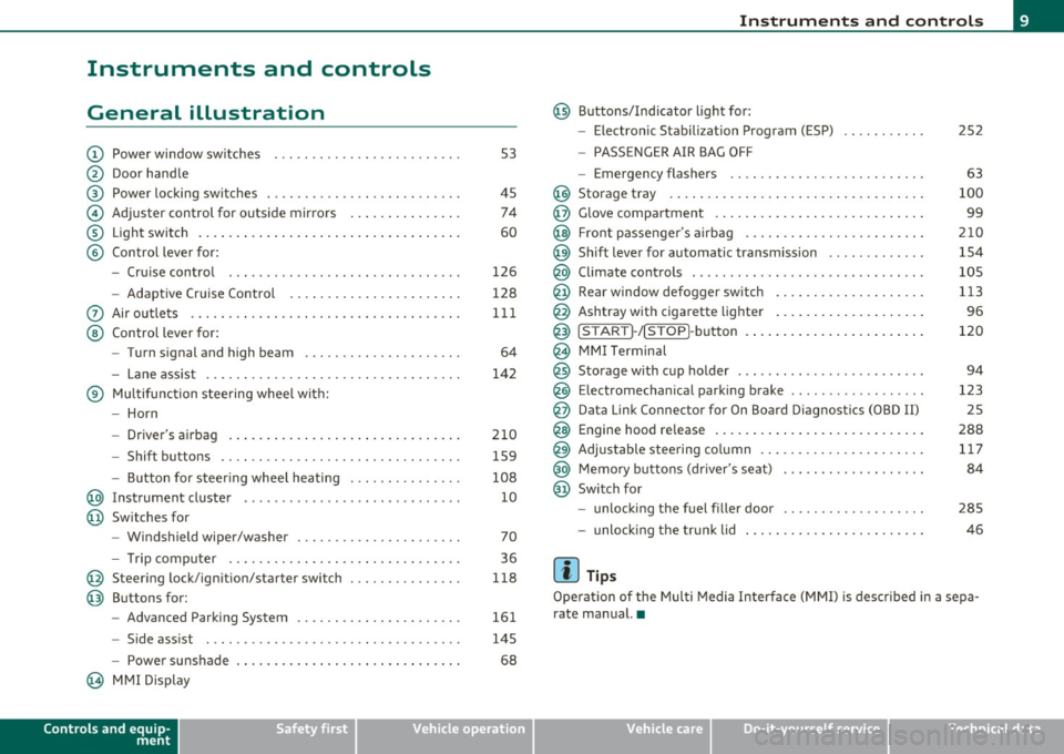
General illustration
(D Power window switches . .. .. .. ... .. ... .. ... ... . .
@ Door handle
@ Power locking switches . .. .. ......... .. .. .... ... .
© Adjuster control for outside mirrors .............. .
® Light switch ............... . ... ..... ....... ... .
© Control lever for:
- Cruise contro l ............ .... ... . ... ....... .
- Adaptive Cruise Control . ................... .. .
0 Air outlets .... .... .. .. .. ... ... ............. .. .
@ Control lever for:
- Turn signal and high beam .................... .
- Lane assist ................ ...... .. .. .. .. ... .
® Multifunction steering wheel with:
- Horn
- Driver's airbag ....................... ....... .
- Shift buttons .... .. .. .. .. .... ............... .
- Button for steer ing whee l heating . .. .. ... ...... .
@ Instrument cluster .................. .... ... ... .
@ Switches for
- Windshield wiper/washer ................ .. ... .
- Tr ip computer .. .......... . .. .... .. .. .... ... .
@ Steering lock/ignition/starter switch .............. .
@ Buttons for:
- Advanced Parking System .... .. .... .. ...... ... .
- Side ass ist ........... ........ ... ..... ... ... .
- Power sunshade
@ MMI Display
Controls and equip
ment Safety first
53
45 74
60
126
128
111
64
142
210 159
108 10
70
36
118
161
145
68
Instruments and controls
@ Buttons/Indicator light for:
- Electronic Stabilization Program (ESP)
- PASSENGER AIR BAG OFF
- Emergency flashers .. .. .. .. .. .... .. ......... .
@ Storage tray .................. .. .. .. ......... .
@ Glove compartment .... .... .. .. .... ........... .
@ Front passenger 's airbag .................... .. . .
@ Sh ift lever for automatic transmission ........... . .
@ Climate controls . .. .................... .... ... .
@ Rear window defogger switch .. .. .. .. .. .... ..... .
@ Ashtray with cigarette lighter ................... .
@ IS TART ]-/IS TOP]-button . ... ................ ... .
@ MMI Terminal
@ Storage with cup holder ..... .. .. .. ............. .
@ Electromechanical parking brake ... .. ...... ..... . .
@ Da ta Link Connector for On Board Diagnostics (OBD II)
@ Engine hood release ........................... .
@ Adjustable steering column ..................... .
@ Memory buttons (driver's seat) .................. .
@ Switch for
- unlock ing the fuel filler door ....... ....... .... .
- unlock ing the trunk lid
[ i ] Tips
252
63
100
99
210
154
105
113
96
120
94
123 25
288 117
84
285
46
Operation of the Multi Media Interface (MMI) is described in a sepa
rate manual. •
Vehicle care Technical data
Page 13 of 384

If the indicator goes all the way to the right side inside the coolant
t empe ra tu re ga uge, the n th e eng ine cool ant tempe rature is too high.
Pull off the road to saf e location , turn off the engine and let it cool
down.
If the warning lig ht comes o n aga in after yo u have driven a
short distance, contact a qualified workshop.
& WARNING
• Always observe the warning in ::::> page 281 , "Engine compart
ment ", before opening the hood and checking the engine coolant
l e vel.
• Never open the engine hood if you see or hear steam, or if you
see engine coolant dripping from the engine compartment. You
c ould burn yourself. Let the engine cool off first so that you cannot
hear or see any steam or engine coolant .
0 Note
• Mounting additiona l lights or accessories in front of the a ir in lets
reduces the cooling effect of the radiator. At high outside tempe ra
tu res o r high engine load, the e ng ine could ove rheat .
• T he front spoi le r has bee n designed to properly distribu te the
cooling air when the vehicle is moving . If the spoiler is damaged, this
co uld reduce the coo ling effect and the eng ine could then overheat.
Ask your author ized A udi deale r for assistance. •
Tachometer (engine rev counter)
The tac home te r indicates the engine RPM (revoluti ons
pe r minu tes) .
The tachometer @::::> page 10, fig. 2 is the left of t he two large clock
type displays .
Th e eng ine tu rns at a speed
1,000 times t h e si ng le dig it in t he
display, e .g. if the need le is pointing at the "2" the engine is tu rning
at 2, 000 R PM.
Controls and equip
ment Safety first
Instruments and warning
/indicator lights
If e ngine RPM drops below 1,500, you s hould dow nsh ift to t he next
lower ge ar. T he re d area at t he e nd of the s cale i ndic ates m aximum
permissible e ngine RPM after the break-in per iod . Before reaching
this area, move the selector lever to posit ion "D (Drive)" or ease yo ur
foot off the accelerator pedal.
0 Note
The tachome ter needle s houl d not move in to the red range. If it does,
then only fo r a very short period of time . You could damage your
e n g in e by driv ing at h igh RPM .
c£> For the sake of the environment
Upshifting early saves fuel a nd reduces e ngine noise. •
Digital clock with date display
Date and time of day can be set in MMI.
Fig. 3 Instrumen t
cluster with digital
clock
Th e da te, time o f day , an d time and date form at can be se t in MM I.
You can find out more in the MMI manual. ..,.
Vehicle care Technical data
Page 14 of 384
![AUDI S8 2010 Owners Manual Instruments and warning/indicator lights
(I] Tips
• The dig ital clock and the odometer are turned on for about 30
seconds when the drivers door is opened.
• When the ign it AUDI S8 2010 Owners Manual Instruments and warning/indicator lights
(I] Tips
• The dig ital clock and the odometer are turned on for about 30
seconds when the drivers door is opened.
• When the ign it](/img/6/57617/w960_57617-13.png)
Instruments and warning/indicator lights
(I] Tips
• The dig ital clock and the odometer are turned on for about 30
seconds when the driver's door is opened.
• When the ign ition is turned off, the odometer read ing and the
digital clock with date display can be switched on for about
30 seconds by press ing the
I CH ECK I button::::> page 13, fig. 5. •
Speedometer with odometer
The speedometer shows you the vehicle speed, and the
odometer shows you how many miles (kilometers) you
have driven.
Fig. 4 Instrume nt
cluster Odometer and res et button
The odometer and trip odometer are located inside the speedometer .
• USA models -Miles
• Canada models -Kilometers
You can switch the display from miles to kilometers and vice versa via
the MMI.
Lower odometer
The lower odometer shows the total number of mi les (kilometers)
driven.
Upper odometer (trip odometer)
The upper odometer shows the total number of miles (ki lometers)
dr iven since you last reset the odometer to zero . You can use th is
odometer when you want to keep track of how many m iles (kilome
ters) you have dr iven for a single trip or errand. The last digit indicates
1/10 of a mile (100 meters) .
You can reset the trip odometer to zero by pressing the Reset button
[0.0].
Malfunction message
If there is a malfunction somewhere in the instrument cluster, dEF
will appear in the trip odometer and will stay on. Contact your autho
rized Audi dealer to have the problem corrected.
Immobilizer
When you switch on the ign ition, the data chip inside the key is "read"
by the immobilizer system.
If an unauthori zed key is inserted into the ignition lock, the word
SAFE will come on and stay on . You will not be able to start the
vehicle=> page
41.
[ i ] Tips
• The digita l clock and the odometer are turned on for about 30
seconds when the driver's door is opened.
• When the ignition is turned off, the odometer reading and the
digital clock with date display can be switched on for about
30 seconds by pressing the [
CHECK] button::::> page 13, fig. 5. •
Fuel gauge
The fuel gauge only works when the ignition is on .
Th e fuel tank holds about 23.8 ga llons (90 liters). When the need le
reaches the reserve mark, the::::> page
33 ) symbol appears in the
instrument cluster display as well as the message
Please refuel. .,_
Page 15 of 384
There is still approximately 2.4 gallons (9 liters) of fuel left. This message is meant to remind you to
refuel.
(D Note
Never run the tank completely dry. An irregular supply of fuel can
cause engine misfiring and fuel could enter the exhaust system. The
catalytic converter could then overheat and be damaged. •
[CHECK) button
You can perform different functions with this button.
Fig. S CHECK button
in the instrument
cluster
The [ CHECK] button performs the following functions:
Switching on the clock and odometer
With the ignition turned off, the odometer reading and the digital
clock with date display can be switched on for about 30 seconds by
pressing the [
CHECK] button~ fig. 5.
Starting the Auto-Check sequence
The Auto-Check system~ page 26 constantly monitors certain indi
vidual functions and components of the vehicle when the ignition is turned on and when the vehicle is moving.
With the ignition turned on, you can start the "Auto-Check sequence"
by pressing the
(CHECK) button. You can perform an Auto-Check
Con tro ls a nd e quip
m en t Vehicle
OP-eration
Instruments and warning/indicator lights
sequence when the vehicle is stationary and the ignition is turned on
or when the vehicle is moving not faster than 3 mph (5 km/h).
Calling up the driver information
A yellow or red symbol appears in the instrument cluster display,
usually with a driver message. The driver message display disappears
after about 5 seconds. The driver message can be displayed again by
briefly pressing the [
CHECK) button.
Setting the speed warning
By pressing the [ CHECK] button briefly, you can set threshold 1 of
the speed warning while you are driving ~
page 35. By maintaining
pressure on the [
CHECK ) button, you delete the warning threshold.•
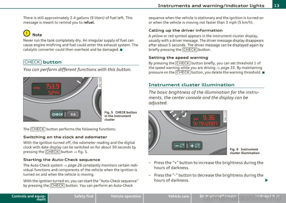
Instrument cluster illumination
The basic brightness of the illumination for the instru
ments, the center console and the display can be
adjusted.
Fig. 6 Instrument
cluster illumination
- Press the"+" button to increase the brightness during the
hours of darkness.
- Press the"-" button to decrease the brightness during the
hours of darkness. .,.
Vehicle care Do-it-yourselt service iTechnical data
Page 16 of 384

Instruments and warning /indicator lights
A light sensor in the instrument cluster controls the illumination for
t he inst rume nt cl uster, the center console and the displays. In a
br ight env ironment , using the buttons to change the brightne ss has
no effect .
[I) Tips
The illumination for the inst rument cluster lights up whenever you
switch on th e ignition with the
vehicl e headlights off . As the daylight
fades, the instrument cluster illumination likewise dims automati
cally and w ill go out completely when the outside light is very low .
Th is fea ture is meant to remind you to sw it ch on the he adlights when
outs ide lig ht condi tions become poor .•
Warning/indicator lights
Overview
The warning/indicator lights indicate different functions
or a possible malfunction .
iNiii i·i i· i hii
F ig . 7 Instr um ent clust er with warn in g/ indicato r lig hts
Your vehicle is equipped w ith several impo rtant warning and ind i
ca tor lights to he lp you moni to r the continued re liable operat ion of
your vehicle =>& .
0
Electronic power control
Generator => page 16
=>page 16
Electronic Stabilization Program (ESP) ~ page 16
Page 18 of 384
![AUDI S8 2010 Owners Manual Instruments and warning /indicator lights
(I] Tip s
Many fun ct ions a re mon itored by the Auto-Check system=> page 26.
Malf unctions or faults will be identified either with a red AUDI S8 2010 Owners Manual Instruments and warning /indicator lights
(I] Tip s
Many fun ct ions a re mon itored by the Auto-Check system=> page 26.
Malf unctions or faults will be identified either with a red](/img/6/57617/w960_57617-17.png)
Instruments and warning /indicator lights
(I] Tip s
Many fun ct ions a re mon itored by the Auto-Check system=> page 26.
Malf unctions or faults will be identified either with a red symbol
(pr iority
1-Dange r!) or with a ye llow symbo l (prio rity 2 -Warn ing). •
Electronic power control C
This warning/indicator light monitors the electronic
power control.
The warn ing/indicator light (Electro nic Power Control) illumi-
nates when you turn on the ignition as a function check .
(I] Tips
If this warning/indicator light illuminates while you are driving, then
there is a malfunct io n in the engine electron ics . Have the ma lfunct io n
corrected as soon as possib le by your authori zed Audi dealer or qual
ified repair fac ility. •
Generator 0
This warning/indicator light detects a malfunction in the
generator or in the vehicle's electrical system.
T he O warning/ind icator light illum inates when you sw itch on the
ignition and must go out after the engine has started .
If the O warning/indicator light illum ina tes while you are d riving,
you should contact your authorized Audi dea ler. Since the veh icle
bat tery is d ischarging, you shou ld switch off any unnecessary elec
trical consumers (for example, the air conditioner) .
0 Note
If the _f_ warn ing/ indicator light (malfunction in the eng ine cooling
system) in the instrument cluster sho uld ill uminate =>
page 29, stop the vehicle and turn off the engine
. The water pump is not working -
t his ca n cause e ngine damage. •
Electronic stabilization program (ESP) ,
This warning/indicator light monitors the electronic
stabilization program .
The war ning/ indicator lig ht has t he fo llow ing funct ions:
• It blinks while you are driving when the ESP is working .
• It illumina tes when yo u sw itch on the ignition for approximate ly 2
seconds as a funct ion check.
• It ill uminates when the re is a malfunct ion in the ESP. T he
message
ESP fault! See owner's manual a lso appears in the instru
ment cl uste r display and a w arning tone sounds.
• It illuminates continuously when the ESP is sw itched off.
• It illum inates if the re is a malfu nction in the ABS, s ince the ESP is
part of the ABS system .
If the battery terminals were disconnected and re- connec ted, the
vehicle was jump started or the battery is very weak, the ESP sensor
system goes thro ugh a learning process for the firs t few yards . The
warning/indicator light illuminates. The warn ing/indicator light goes
out as soon as t he learning process is comp lete.
If the ESP warning/i ndicator lig ht ill uminates and stays on afte r you
have started the engine, t his may mean that the control system has
temporar ily switched off the ESP . If this is case , you ca n react ivate
the ESP by turning the ignition off and then on aga in. The
w ar ning/ind ica tor ligh t shou ld go ou t to show t hat the system is fully
functional again .
For more in formation about the ESP =>
page 252. •
Page 22 of 384

Instruments and warning/indicator lights
Malfunction in the electronic differential lock (EDL)
The ED L works toge ther w ith the ABS. The ABS warn ing lig ht w ill
come on if there is a mal func tion in the EDL system=>
page 253 . See
your authorized A udi dea le r as soon as poss ible .
& WARNING
• If the .. (USA models )/ ...,. (Canada models ) wa rning light
does not go out , or if it comes on while driving, the ABS system is
not working properly. The vehicle can then be stopped only with
the standard brakes (without ABS ). You will not have the p rotec
tion ABS provide s. Contact you r Audi dealer as soon as pos sible .
• USA models: If the BRAKE warning light , the ., warning light
and the warning light come on together , the rear wheel s
could lock up first under hard braking . Rear wheel lock-up can
c ause loss of vehicle control and an accident. Have you r vehicle
repaired immediate ly by your authorized Audi dealer or a qualified
workshop. Drive slowly and avoid sudden, hard brake applica
tions .
• Canada models: If the brake warning light «D>, the wa rning
light and the ABS warning light come on together, the rear
wheels could lock up first under hard braking. Rear wheel lock-up
can cause los s of vehicle control and an accident . Have your vehicle
repaired immediately by your authorized Aud i dealer or a qualified
workshop . Drive slowly and avoid sudden, hard brake
applic ations. •
Electromechanical parking brake
::E {USA models) / (®) {Canada models)
The warning/indicator light monit ors the electromechan
ical parking broke .
With the pa rking bra ke app lied and the ignition t urned on, the
wa rning/ind icator light illuminates. Afte r the ign it ion has been
t u rne d off, the wa rning/indicator light continues to illuminate for about 30 seconds.
If the park
ing brake is applied w ith the ign ition
tur ned off, the w arning/ind ic a tor ligh t illumi nates fo r abo ut 3 0
seconds.
Th e warning/ind icator light will go out when the parking brake is
re lease d.
If the war ning/ indicator lig ht flashes cont inuous ly
after applying the
p ar king bra ke, bra king fo rce is no t sufficien t to prevent the vehicle
from rolling unintentionally . T his can happe n if the brakes become
too hot. P lease note the fo llowi ng:
• If the slope of the ground is too s teep to par k the ve hicl e, th e addi
tional drive message appea rs
Caution: Vehicle parked too steep .
• In the event of a pa rking brake mal func tion, the yellow • symbol
appea rs in the instrument cluste r display and the driver message
Parking brake malfunction! is d isplayed. Have t he ma lf u n ct io n
re paire d as soon as possib le by a q ualified Audi dealership .•
Brake system BRAKE (USA
models)
/ (CD) {Canada models)
The warning/indicator ligh t flashes if brak e fluid l eve l is
low, if there is an A BS system malfunction or a parking
brake malfunction.
Th e light illum ina tes when the igni tion is t urned o n. It goes out after
the engine has been started . This indicates that t he brake warn ing
light is fu nctioni ng p roperly.
If the brake warning light does not light up when the engine is
cranking , there may be a malfunction in the electrical system. In
this case, contact your Audi dealer.
If the brake system wa rning/indicator light flashes, there is a brake
system malfunc tion . By press ing the
I C H ECK ] button, you can b ring
up a driver message which explains the malfunction in mo re detail
=>
page 28. ~
Page 24 of 384
Driver information displ ay
Driver information display
Introduction
General notes
The driver information display inside the instrument
cluster provides you, the driver, with much useful infor
mation .
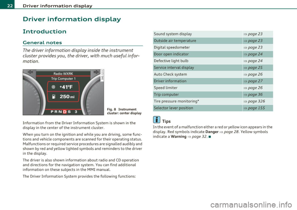
Fig. 8 Inst rument
cluster: center d isplay
Informat ion from the Driver Information System is shown in the
display in the center of the instrument cluster.
When you tu rn on the ign ition and while you are driving, some func
tions and vehicle components are scanned for their operating status. Malfunctions or required service procedures are signalled audibly and
shown by red and yellow lighted symbols and reminders to the driver
in the display .
T he d river is a lso shown information about radio and CD operation
and directions for the navigation system. You can find additional
information on these subjec ts in the MMI manual.
The Driver Informat ion System provides the following functions: Sound system display
:::>
page23
Outside air temperature :::>page23
Digital speedometer :::>page23
Door open indicator :::>page24
Defective light bulb :::>page24
Service interval display :::> page25
Auto Check system :::> page26
Driver information :::>page27
Speed limiter :::>page26
Trip computer :::> page36
Tire pressure mon itoring* :::>page326
Selector lever position => page 155
[]] Tips
In the event of a malfunction either a red or yellow ico n appea rs in the
display . Red symbols indicate
Da nge r=> page 28. Yellow symbols
ind icate a
Wa rning => page 32. •