center console AUDI S8 2012 Owners Manual
[x] Cancel search | Manufacturer: AUDI, Model Year: 2012, Model line: S8, Model: AUDI S8 2012Pages: 300, PDF Size: 75.06 MB
Page 4 of 300
2 Table of contents Vehicle literature .. .. .. .. .. ... .
5
About this Owner's Manual . . . 6
Controls and equipment .. ... .
Instruments and controls .. . .
General illustration ......... .. ... .
Instruments and warning/
indicator lights ........ .. .. .. . .
Instruments ............ ... .. ... .
Warning/indicator lights .......... .
Driver information display .. .. .. ... .
On-Board Diagnostic system (OBD) . . .
Opening and closing .. .. .... . .
Keys .. ...... ........... .. .. ... .
Power locking system ..... .. .. .. . .
Rear lid .. .. ........ ..... .. ..... .
Child safety lock . .......... ... .. . .
Power windows . .......... ... .. . .
Valet park ing . ........... .. .. ... .
Sliding/tilting sun roof ... .. .. .. .. . . 8
8
8
10
10
11
23
26
28
28
30
34
37
38
39
40
Panoramic sunroof. . . . . . . . . . . . . . . . 41
Clear vision .. ........ .. .. .. .. . .
Lights ... .. ............. .. .. .. . .
I nterior lights .............. .. ... .
V1s1on ..... ... .... ......... .... .
Wiper and washer system ... ... .. . .
Mirrors ................. .. .. ... .
Digital compass .......... .... ... .
Seats and storage ....... .. .. . .
General recommendat ions ..... .. . .
Front seats .............. .... ... .
Rear seats .. ... .. .. ..... ... .. .. . . 43
43
46
47
48
51
52
54
54
55
57
He ad restraints . . . . . . . . . . . . . . . . . . 61
Seat memory . ... ..... ... .. .. .. . .
Full-length center console .... .. ... . 62
64
L uggage compartment . . . . . . . . . . . . 66
Pa ss-thro ugh with ski sack . . . . . . . . . 67
Roof rack . . . . . . . . . . . . . . . . . . . . . . . 68
12-vo lt sockets . . . . . . . . . . . . . . . . . . . 70
Storage . . . . . . . . . . . . . . . . . . . . . . . . . 71
Cooler . . . . . . . . . . . . . . . . . . . . . . . . . . 72
Warm and cold ... .......... .. .
Climate controls . .... .......... .. .
On the road ... ... .......... .. .
Steering .. .... .. ... .. ........ .. .
Starting and stopping the engine ... .
E lectromechanical parking brake ... .
Speed warning system ............ .
Cru ise control .... .... ...... ... .. .
Audi adaptive cruise control
and braking guard ......... .. .
Introduction . .. .. ..... ......... . .
General information ............. .
Audi adaptive cruise control ... .. .. .
Audi braking guard ............ .. .
Messages . .. .. . .............. .. .
Audi lane assist ............ .. .
Lane assist ...... ............. .. .
Audi side assist .............. .
Lane Change Assistant ........ .. .. . 75
75
79
79
80
82
84
85
8 7
87
87
89
93
94
96
96
99
99
Audi drive select . . . . . . . . . . . . . . 103
Driving settings . . . . . . . . . . . . . . . . . . 103
Raising/lowering the vehicl e . . . . . . . . 105
Driver messages . . . . . . . . . . . . . . . . . . 105
Night vision assistant . . . . . . . . . 106
Description . . . . . . . . . . . . . . . . . . . . . . 106
Pedestrian detection . . . . . . . . . . . . . . 106
Pedestrian warning . . . . . . . . . . . . . . . 106
General information . . . . . . . . . . . . . . 107
Switching on and
off . . . . . . . . . . . . . . 107
Settings in the MMI . . . . . . . . . . . . . . . 108
Driver messages . . . . . . . . . . . . . . . . . . 108
Automatic Transmission . . . . . . 10 9
t ip tron ic (8 -speed transmission) . . . . . 109
Page 11 of 300
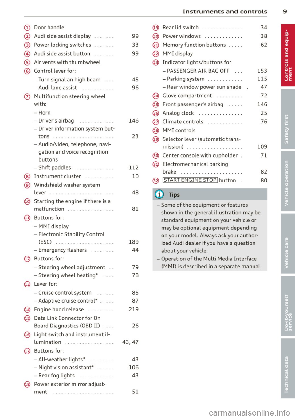
(!) Door handle
@
®
©
®
®
Audi side assist d isplay
Power locking sw itches
Audi side assist button
A ir vents with thumbwheel
Control leve r for :
- Turn signal an high beam
- Audi lane assist ..... ... .. .
0 Multifunction steering wheel
with:
- Horn
- Drive r's airbag
- Driver information system but-
tons . ............... .. .. .
- Audio/video, telephone, navi
gation and vo ice recognition
buttons
- Sh ift padd les ........ .. .. .
@ Instrument cluster .. ... .. .. .
® W indshield washer system
l ever .................... . .
@ Starting the engine i f there is a
malfunction . .. ..... ... .. .. .
@ Buttons for:
- MM I display
- Electronic Stab ility Contro l
( E SC) .. ............. .... .
- Emergency flashe rs . ..... . .
@ Buttons for:
- Steering wheel adjustment
- Steering wheel heating*
@ Lever for:
- Cruise contro l system
99
33
99
45
96
146
23
1 12
10
48
8 1
189
44
79
78
85
- Adaptive cruise cont ro l* . . . . . 87
(§ Eng ine hood re lease . . . . . . . . . 219
@ Data Link Connector for On
Board Diag nostics (OBD II) . . . . 26
@ Light switch and inst rument il-
l umination . . . . . . . . . . . . . . . . . 43, 47
@ Buttons for :
- All-wea ther lights* 43
- Nigh t vision assista nt* . . . . . .
106
- Rea r fog lights . . . . . . . . . . . . 43
@ Power exterior mirror adjust -
ment . . . . . . . . . . . . . . . . . . . . .
51
In strument s and control s 9
@) Rear lid switch .... .. .. ..... .
@ Power w indows .. .......... .
@ Memo ry function buttons .... .
@ MMI display
@ I n d icator lights/buttons for
- P ASSENG ER AIR BAG OFF
- Par king system . .. ........ .
- Rear w indow power sun shade
@ G love compartment . ..... .. .
@
@
@
Front passenger's airbag .... .
Analog clock .. .. .. ........ .
Climate controls
@ MMI controls
@ Se lector lever (a utomat ic trans-
m1ss1on) . ........ .. .. ..... .
@ Center console w ith cupholder
@ El ectromechanical pa rking
br ake .. .. .. .. .... ........ .
@ I START ENGINE STOPI button
(D Tips
34
38
62
153
115
47
72
146
25
76
109
71
82
80
- Some of the equipment o r feat ures
shown in the genera l ill ustration may be
standard equ ipment on your vehicle or
may be opt ional equ ipment depending
on your model. Always ask your author
ized Aud i dea ler if you have a quest io n
about your vehicle .
- Operat ion of the Multi Med ia Interface
(MMI) is described in a separate manua l.
Page 27 of 300
Instruments and warning/indicator lights 25
For some vehicle functions, you can access the
trip information from the temporary memory
in the line
(I) c:;; page 23, fig. 5.
@ Tips
- All stored values will be lost if the vehi
cle battery is disconnected.
- Fuel consumptions (average and cur
rent), range and speed are displayed in
metric units on Canadian models.
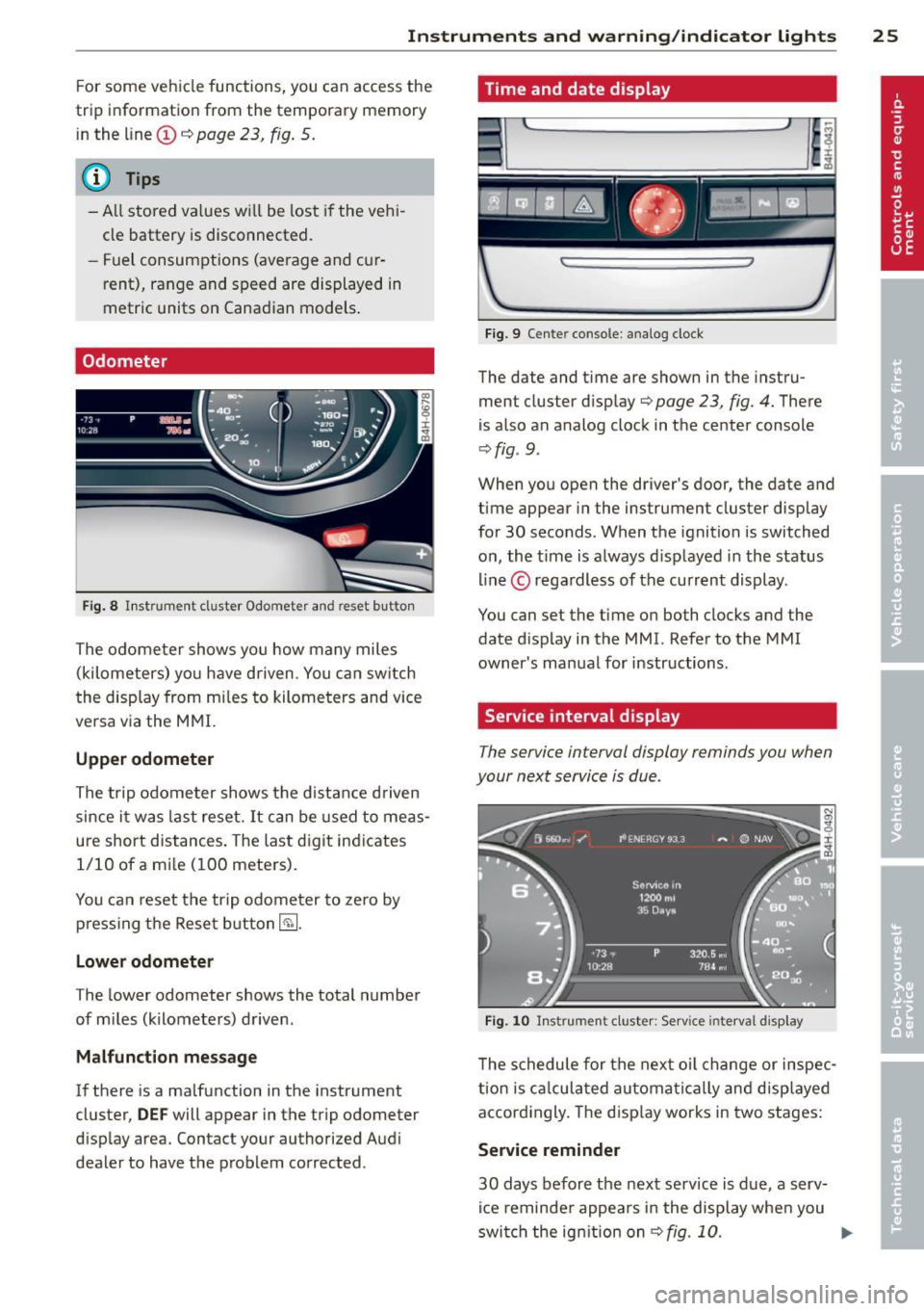
Odometer
Fig. 8 Instrument cluster Odometer and reset b utto n
The odometer shows you how many miles
(kilometers) you have driven. You can switch
th e display from miles to kilometers and vice
versa via the MMI.
Upper odometer
The trip odometer shows the distance driven
since it was last reset.
It can be used to meas
ure short distances. The last digit indicates 1/10 of a mile (100 meters).
You can reset the trip odometer to zero by
pressing the Reset button~-
Lower odometer
The lower odometer shows the total number
of miles (kilometers) driven .
Malfunction message
If there is a malfunction in the instrument
cluster,
DEF will appear in the trip odometer
display area. Contact your authorized Audi
dealer to have the problem corrected .
Time and date display
...
I~
Fig. 9 Cente r console : analog clock
The date and time are shown in the instru
ment cluster display
c:;; page 23, fig. 4. There
is also an analog clock in the center console
¢fig . 9 .
:r
~
When you open the driver's door, the date and
time appear in the instrument cluster display
for 30 seconds. When the ignition is switched
on, the time is always displayed in the status
line © regardless of the current display.
You can set the time on both clocks and the
date display in the MMI. Refer to the MMI
owner's manual for instructions.
Service interval display
The service interval display reminds you when
your next service is due .
Fig. 10 Instrument cluster: Serv ice inte rval disp lay
The schedule for the next oil change or inspec
tion is calculated automatically and displayed
accordingly. The display works in two stages:
Service reminder
30 days before the next service is due, a serv
ice reminder appears in the display when you
switch the ignition on
¢fig. 10. ..,.
Page 46 of 300
44 Clear vision
Highway light function* (vehicles with LED
headlights) -this function adapts the lighting
for highway driving based on vehicle speed.
.&_ WARNING
- Automatic headlights are only intended
to assist the driver. They do not relieve
the driver of his responsibility to check
the headlights and to turn them on man
ually according to the current light and
visibility conditions. For example, fog
cannot be detected by the light sensors.
So always switch on the headlights §.0
under these weather conditions and
when driving in the dark.
- Crashes can happen when you cannot see the road ahead and when you cannot be
seen by other motorists. Always turn on
the headlights so that you can see ahead
and so that others can see your car from
the back.
- Please observe legal regulations when
using the lighting systems described.
(D Note
The rear fog lights should only be turned
on in accordance with traffic regulation, as
the lights are bright for following traffic.
@ Tips
- The light sensor* for automatic dynamic
headlight range control* is located in the
rear view mirror mount. You should
therefore not apply any stickers to the
windshield in this area in order to pre
vent malfunctions or failures .
- In the event of a light sensor malfunc
tion, the driver is notified in the instru
ment cluster display¢
page 21 .
- You will hear a warning tone if you open
the driver door when the exterior lights
are switched on.
- In cool or damp weather, the inside of
the headlights, turn signals and tail
lights can fog over due to the tempera
ture difference between the inside and
outside. They will clear shortly after switching them on. This does not affect
the service life of the lighting.
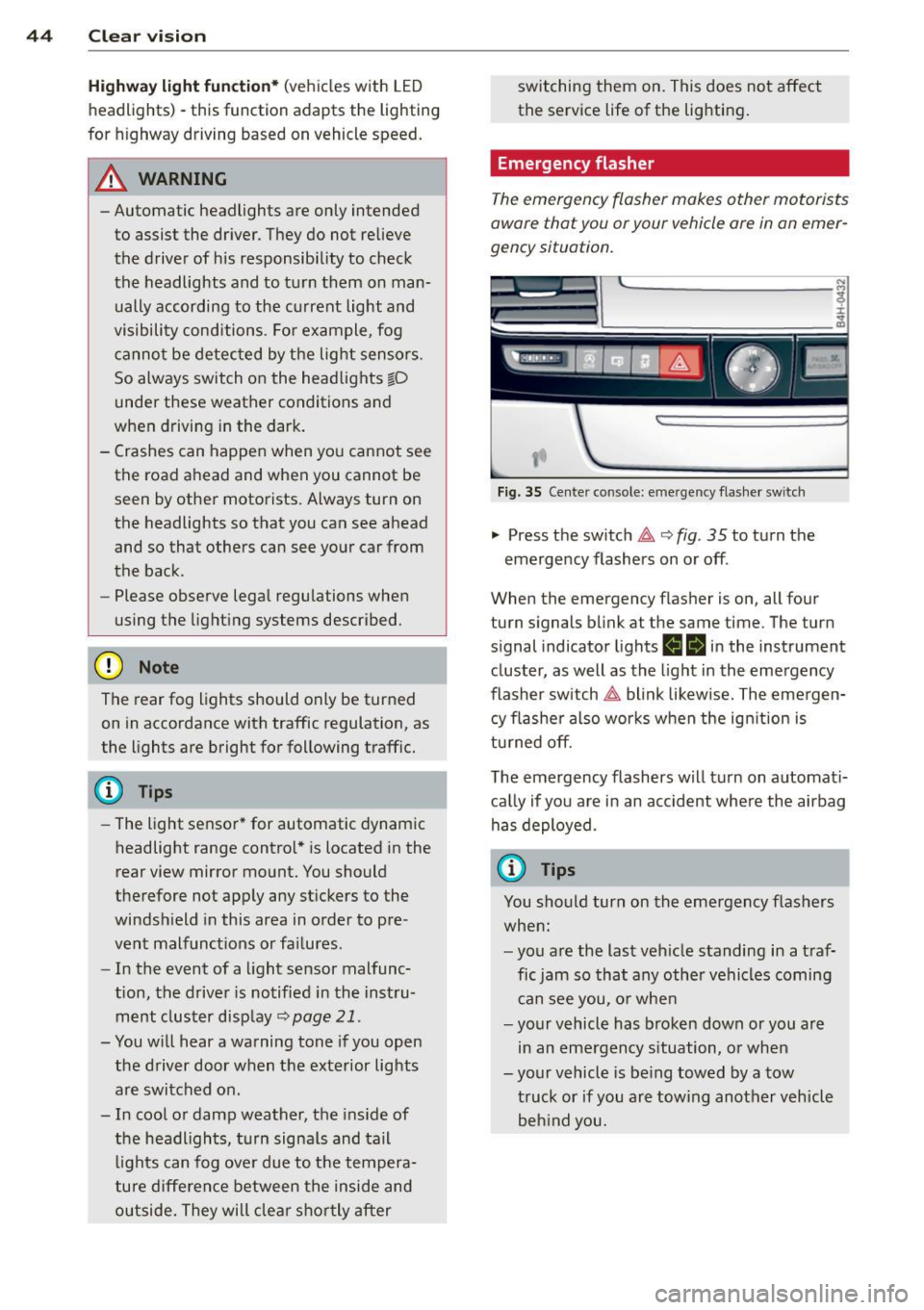
Emergency flasher
The emergency flasher makes other motorists
aware that you or your vehicle ore in an emer
gency situation.
,--~
,_'
. ;.' --- --~-.sc-
Fig. 35 Center console: emergency flasher switch
.,. Press the switch 11 ¢ fig. 35 to turn the
emergency flashers on or off .
When the emergency flasher is on, all four
turn signals blink at the same time. The turn
s ignal ind icator lights
ea in the instrument
cluster, as well as the light in the emergency
flasher switch
11 blink likewise. The emergen
cy flasher also works when the ignition is
turned off.
The emergency flashers will turn on automati
cally if you are in an accident where the airbag
has deployed.
(D Tips
You should turn on the emergency flashers
when:
- you are the last vehicle standing in a traf
fic jam so that any other vehicles coming
can see you, or when
- your vehicle has broken down or you are
in an emergency situation, or when
-your vehicle is being towed by a tow
truck or if you are towing another vehicle
behind you.
Page 50 of 300
48 Clear vis ion
Extending /retracting th e re ar window
s h ad e*
• To extend or retract the sun shade from the
cockpit ,
press the rn button in the center
console
c> fig . 41 .
• To extend or retract the sun shade from the
r e ar of th e vehicle,
press the liiil button in
the door
c> fig . 42 .
Extending the re ar door sun shade s*
• Close the window in the rear door.
• To extend the sun shade
from the d rive r's
s eat ,
pull the left/right rear power window
switch~ in the driver's door .
• To extend the sun shade from the
rear of
th e v ehi cle,
pull the power window sw itch
~ in the left/right rear door.
Re tra cting the re ar doo r sun shades*
• To retract the sun shade from the driv er's
sea t,
press the left/right rear power window
switch~ in the driver's door .
• To retract the sun shade from the
re ar of
th e vehi cle,
press the power window swit ch
~ in the left/ right rear door .
You can adj ust the settings for the rear sun
shade so the shade ret ra cts automa tically
when you selec t the reve rse gear. Select:
CAR
function button > C ar sys tems control button
> Vehicle set tings > Aut omatic rear blind >
On. T he sett ings are automat ica lly stored and
assigned to the remote control key . The sun
shade extends again as soon as the veh icle be
g ins traveling forward at a speed greater than
9 mph (1S km/h), as long as the ignition has not been switched off in th e mea ntime .
& WARNING
When lowe ring or raisi ng the sunshade,
make s ure there is no thing in its way and
t ha t it has a free path to trave l. This could
cause personal injury.
{D) Tips
- Pressing the b utton rn several times
consecutively can tr igger the overload
protection . The sun shade can only be ex- tended/retracted again after a brief wait
ing period.
- The rear window sun shade on ly func
tions when the vehicle interior is warmer
than 14°F (-10°C) .
Vanity mirror in the rear
Applies to vehicles: with vanity mirrors in the rear
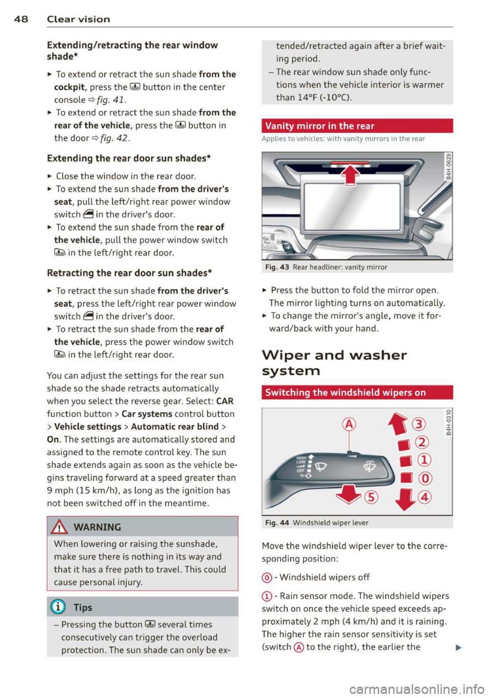
Fig. 43 Rear hea dliner: van it y m irror
• Press the b utton to fold the m irror open.
The mir ro r li ght ing turns on automatically.
• To c hange the mir ro r's ang le, move it for
ward/back with your hand .
Wiper and washer
system
Switching the windshield wipers on
Fig . 44 Winds hield w iper leve r
Move the windshie ld wiper lever to the corre
sponding posit ion :
@ -Windshield wipers off
(D -Rain sensor mode. The windshield wipers
switch on once the vehicle speed exceeds ap
proximate ly 2 mph (4 km/h) and it is raining.
The higher the rain sensor sensit ivity is set
(sw itch @ to the right), the earlier the
Page 60 of 300
58 Seats and storage
© -Switching front passenger seat adjust
ment on/off: this function must be activated
in the MMI ¢
page 60, ¢& .To switch front
passenger seat adjustment on, press the but
ton. You can now adjust the front passenger
seats us ing the buttons @ and @. If you do
not press the buttons @ or@ , front passen
ger seat adjustment switches
off automatica l
ly after approximate ly ten seconds.
& WARNING
- T he power adjustment for the individ ual
seats also works with the ignition . For
this reason, children should never be left
unattended in the vehicle -th ey could be
injured!
- Exercise caution when adjusting the
seats. Uns upervised or careless seat ad
justment can p inch fingers or hands
causing injur ies.
- Vehicles with a pass through in the cen
ter console have seat ing for four. The
long center console between the two
Reclining rear seat overv iew
Applies to vehicles: with reclining rear seat
----------------- T ® ------ -
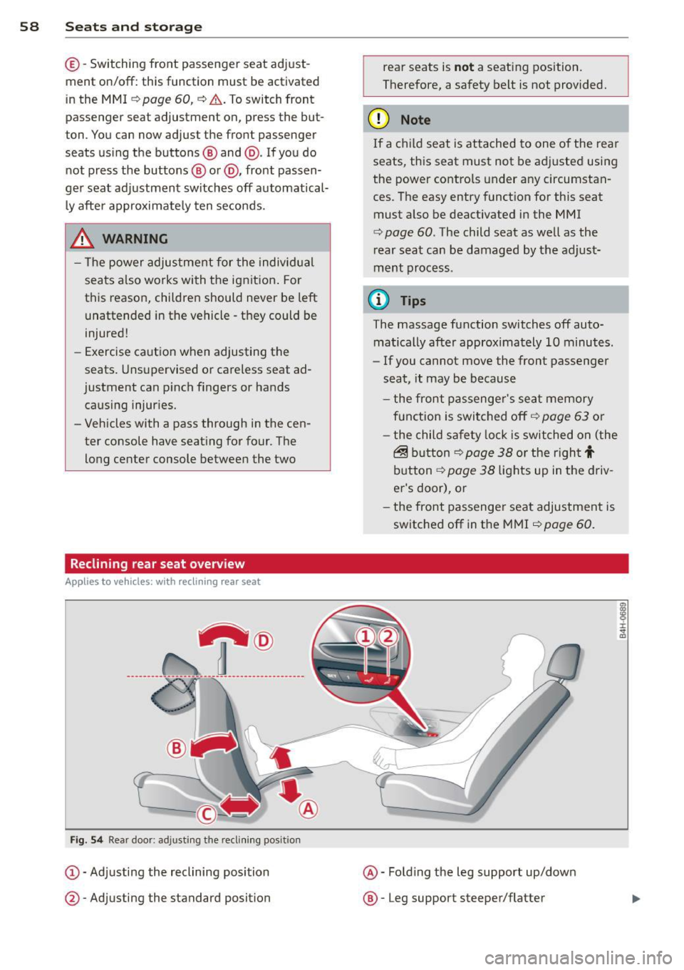
Fi g. 54 Rear doo r: ad justi ng the recli ning posit ion
(D -Adj usting the reclining posi tion
@ -Adjusting the standard position rear seats is
n
ot a seat ing position.
Therefore, a safety belt is not provided.
(D Note
If a child seat is attached to one of the rea r
seats, this seat must not be adj usted using
the power controls under any circumstan
ces. The easy entry funct ion for this seat
must also be deactivated in the MMI
¢
page 60 . The child seat as well as the
r ear seat can be damaged by the adjust
ment process.
© Tips
The massage function switches off auto
matically after approximately 10 minutes.
- If you cannot
move the front passenger
seat, it may be because
- the front passenge r's seat memory
f u nction is swi tched off ¢
page 63 or
- the child safety lock is switched on (the
@ b utton ¢ page 38 or t he righ t t
button ¢ page 38 lights up in the d riv
er's door), or
- the front passenger seat adjustment is
switched
off in the MMI ¢ page 60.
@ -Fold ing the leg support up/down
@ -Leg support steeper/flatter
i :c ., a,
Page 62 of 300
60 Seats and storage
Massage function remote control
Applies to vehicles: with reclining rear seat and massage
f u nct ion
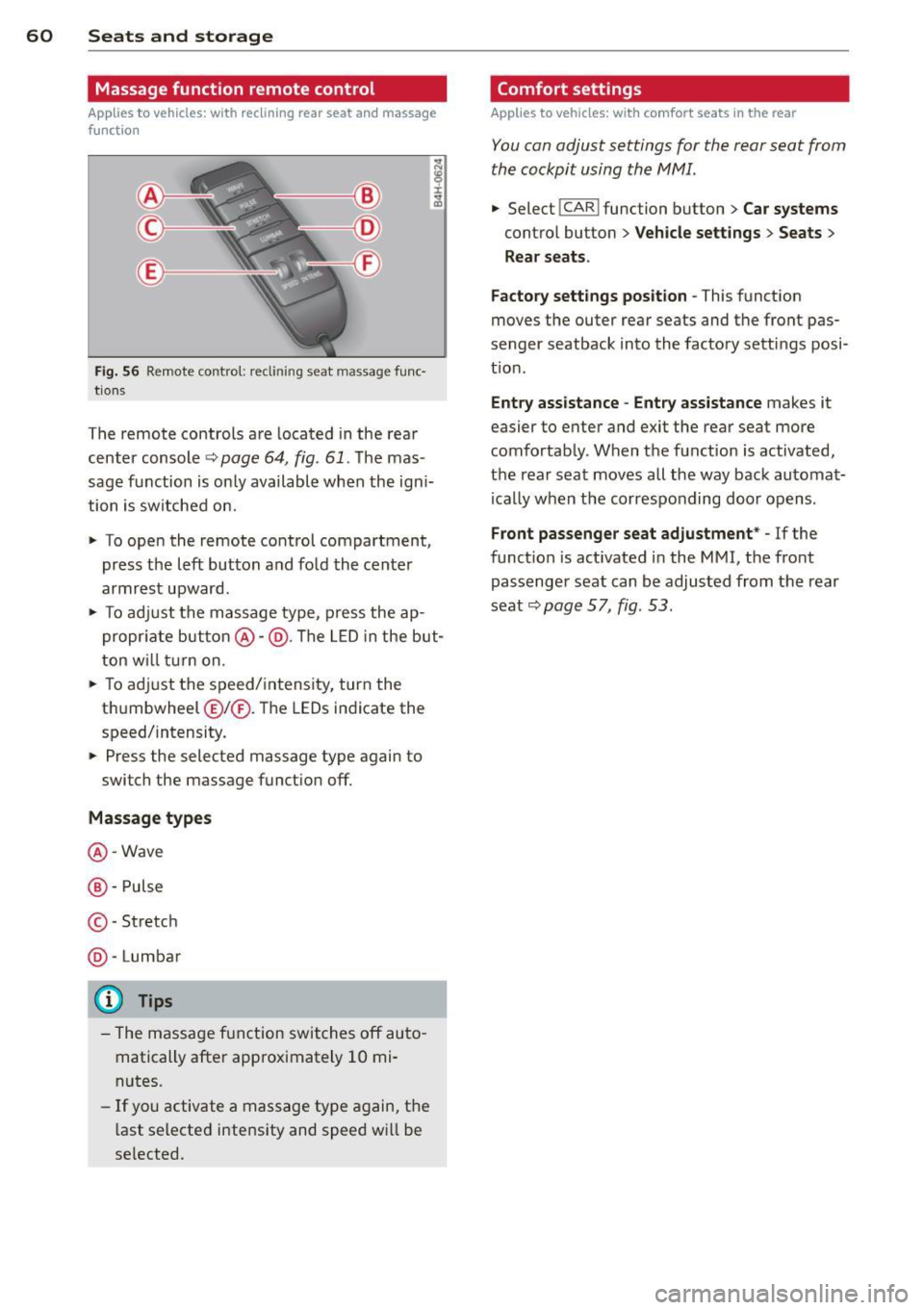
Fig. 56 Remote contro l: recli nin g seat massage func·
tions
The remote controls are located in the rear
center console
Q page 64 , fig . 61. Th e mas
sage function is only available when the ign i
tion is switched on.
" To open the remote control compartment,
press the left button and fold the center
armrest upward .
" To adjust the massage type, press the ap
propriate button@-@ . The LED in the but
ton will turn on.
" To adjust the speed/ intensity, turn the
t hu mbwheel @I® . Th e LEDs indicate the
speed/intensity.
" Press the selected massage type again to
switch the massage function off.
Massage types
@-Wave
@ -Pulse
© -St retch
@ -Lumbar
(D} Tips
- The massage function switches off auto
matically after approximately 10 mi·
nutes.
- If you activate a massage type again, the
l ast selected intensity and speed wi ll be
se lected.
Comfort settings
Applies to vehicles: wit h comfort seats in the rear
You can adjust settings for the rear seat from
the cockpit using the MMI.
" Selec t! CAR I function button > Car systems
contro l button > Vehicle settings > Seats >
Rear seats.
Factory settings position -
This function
moves the outer rear seats and the front pas
senger seatback into the factory settings posi
t ion .
Entry assistance -Entry assistance makes it
easier to enter and exit the rear seat more
comfortably. When the function is activated,
the rear seat moves all the way back automat
i ca lly when the corresponding door opens .
Front passenger seat adjustment* -If the
function is act ivated in the MMI, the front
passenger seat can be adjusted from the rear
seat
Q page 57, fig . 53 .
Page 63 of 300
Head restraints
Adjusting the head restraints
Head restraints that are adjusted according
to body size, along with the safety belt, offer
effective protection .
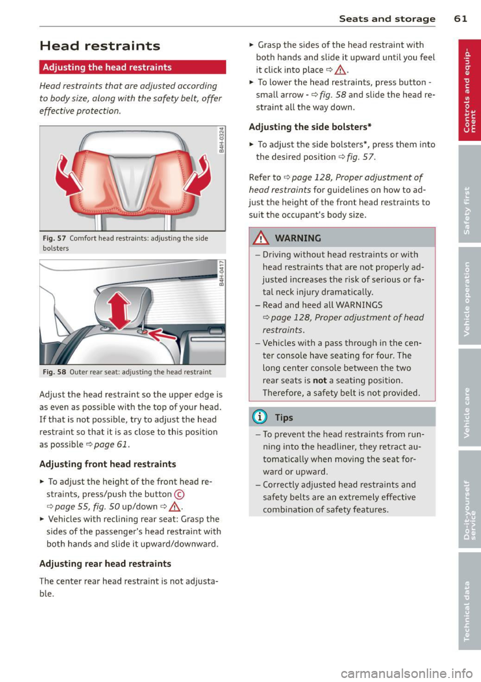
Fig. 57 Comfort head restraints: adjusting th e s ide
bolsters
Fig. 58 Outer rear seat: adjusting the h ead restraint
Adjust the head restraint so the upper edge is
as even as possible with the top of your head.
If that is not possible, try to adjust the head
restra int so that it is as close to this position
as possible
c:> page 61.
Adjusting front head restraints
• To adjust the height of the front head re
stra ints, press/push the button ©
o page 55, fig . SO up/down o _& .
• Vehicles with reclining rear seat: Grasp the
s ides of the passenger 's head restraint with
both hands and s lide it upward /downwa rd.
Adjusting rear head restraints
The center rear head restra int is not adjusta
b le .
Seats and storage 61
• Grasp the sides of the head restraint with
both hands and slide it upward until you feel
it click into place
c:> ,&..
• To lower the head restraints, press button -
small arrow -
o fig. 58 and slide the head re
straint all the way down .
Adjusting the side bolste rs*
• To adjust the side bolsters *, press them into
the desired position
c:> fig. 57.
Refer to
c:> page 128, Proper adjustment of
head restraints
for guidelines on how to ad
just the height of the front head restraints to
suit the occupant's body size.
&_ WARNING
-
-Driving without head restraints or with
head restraints that are not properly ad
justed increases the risk of ser ious or fa
tal neck injury dramat ica lly.
- Read and heed all WARNINGS
c:> page 128, Proper adjustment of head
restraints.
- Vehicles w ith a pass through in the cen
ter console have seating for four. The long center console between the two
rear seats is not a seating position.
Therefore, a safety belt is not provided.
(D Tips
-To prevent the head restraints from run
ning into the headliner, they retract au
tomatically when moving the seat for
ward or upward.
- Correctly adjusted head restraints and
safety belts are an extremely effective
combination of safety features.
Page 66 of 300
64 Seats and storage
Full-length center
console
Overview
Appl ies to vehicles: with full-len gth ce nter console
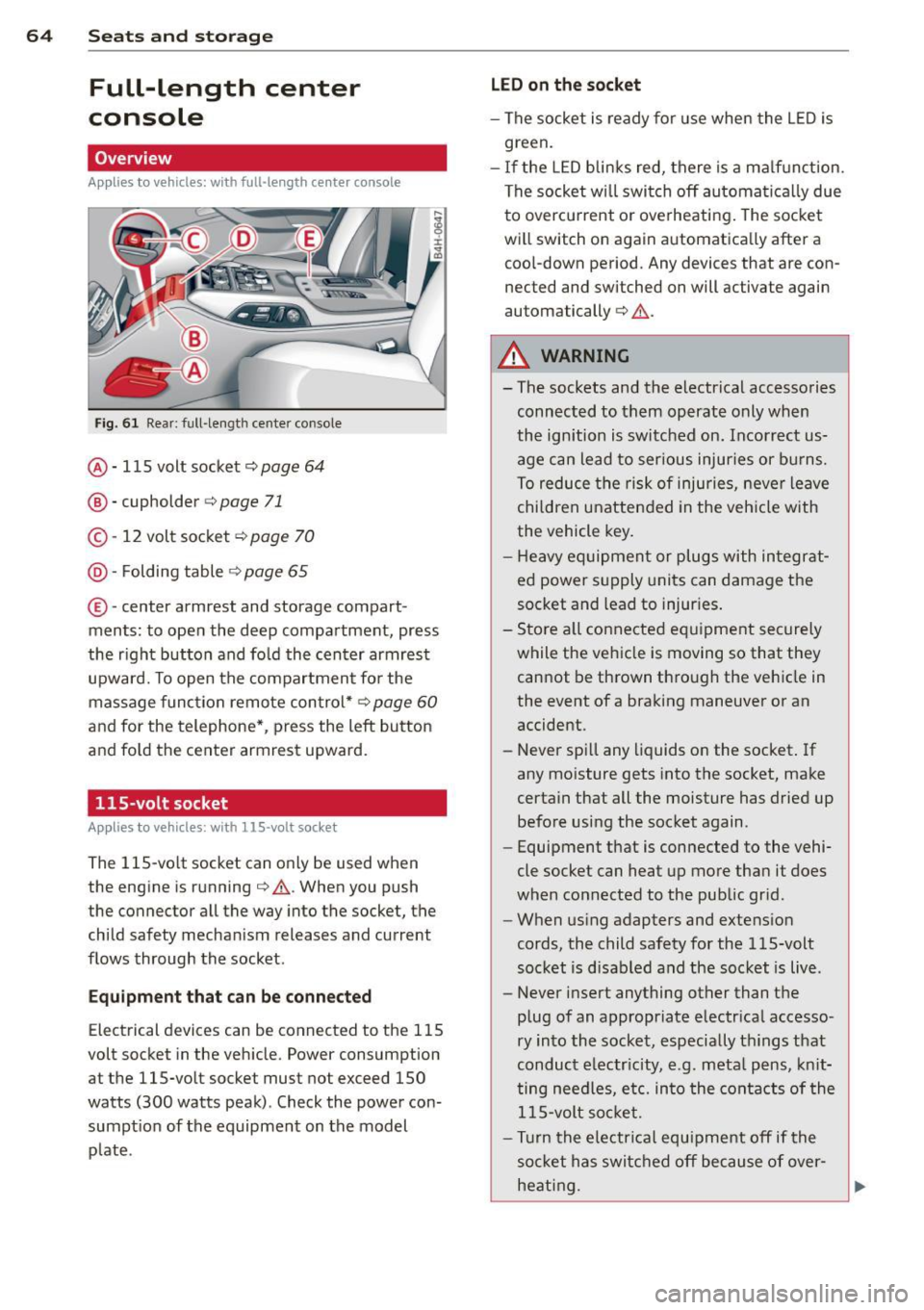
Fig. 61 Rear: full -length center console
@ · 115 volt socket ¢ page 64
@ · cupholder <=> page 71
© · 12 volt socket c:> page 70
@ · Folding table ¢ page 65
®·center armrest and storage com part ·
ments: to open the deep compartment, press
the right button and fold the center armrest
upward. To open the compartment for the
massage function remote control*
c:> page 60
and for the telephone*, press the left button
and fold the center armrest upward.
115-volt socket
Applies to vehicles: with 115 -vo lt socket
The 115-volt socket can only be used when
the engine is running¢
A. When you push
the connector all the way into the socket, the
child safety mechanism releases and current
flows through the socket .
Equipment that can be connected
Electrical devices can be connected to the 115
volt socket in the vehicle. Power consumption
at the 115-volt socket must not exceed 150
watts (300 watts peak) . Check the power con·
sumption of the equipment on the model
plate .
LED on the socket
-The socket is ready for use when the LED is
green.
- If the LED blinks red, there is a malfunction.
The socket will switch off automatically due
to overcurrent or overheating. The socket
will switch on again automatically after a cool-down period. Any devices that are con
nected and switched on will activate again
automatically
c:> A .
A WARNING
-
- The sockets and the electrical accessories
connected to them operate only when
the ignition is switched on. Incorrect us
age can lead to serious injuries or burns.
To reduce the risk of injuries, never leave
children unattended in the vehicle with
the vehicle key.
- Heavy equipment or plugs with integrat
ed power supply units can damage the
socket and lead to injuries.
- Store a ll connected equipment securely
while the vehicle is moving so that they
cannot be thrown through the vehicle in
the event of a braking maneuver or an
accident.
- Never spill any liquids on the socket. If
any moisture gets into the socket, make
certain that all the moisture has dried up before using the socket again.
- Equipment that is connected to the vehi·
cle socket can heat up more than it does
when connected to the public grid .
- When using adapters and extension
cords, the child safety for the 115-volt
socket is disabled and the socket is live.
- Never insert anything other than the
plug of an appropriate electrical accesso·
ry into the socket, especially things that
conduct electricity, e.g. metal pens, knit
ting needles, etc. into the contacts of the
115-volt socket.
- Turn the electrical equipment off if the
socket has switched off because of over·
heating.
Page 67 of 300
(D Note
-Always follow the manufacturer's in
structions for all electrical accessories
you want to use with the electrical sock
et!
- Do not connect lamps that contain a ne
on tube. For technical reasons the lamp
may be damaged.
- Do not connect any 230-volt equipment
to the 115-volt socket. The equipment
may be damaged. If necessary, check the
permissible voltage for the equipment
on the mode l label.
- In the case of some power packs, e.g . for
a laptop computer, the bu ilt-in overcur
rent shutoff prevents it from be ing
swi tch ed on because of excessive start
up current. In this case, disco nnect the
power pack from the consumer and re
connect it after about 10 seconds.
(I) Tips
- Unshielded equipment may cause inter
ference in the radio and the vehicle elec
tronics.
- Some eq uipment may work properly be
cause of the reduced power (wattage),
available from the socket.
Folding table in the center console
Applies to vehicles: with fold ing table in the center con·
so le
The folding table is stored in the front area of
the center console .
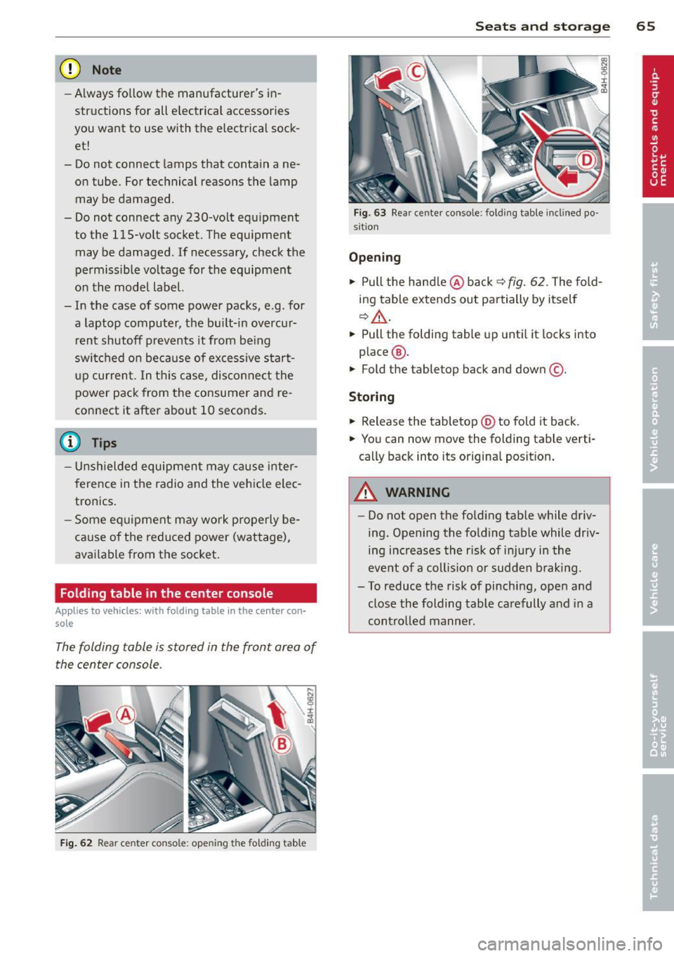
Fig . 62 Rear center console: opening th e fo ld in g table
Seats and storage 65
Fig. 63 Rear center console: fold ing table inclined po ·
s itio n
Opening
.,. Pull the handle @back q fig. 62. The fold
ing table extends out partially by itself
~.&. -
.. Pull the folding table up until it locks into
place @.
.. Fold the tabletop back and down©-
Storing
.. Release the tabletop @to fold it back.
.. You can now move the folding table verti·
cally back into its original posit ion .
A WARNING
-Do not open the folding tab le while driv
ing. Opening the folding table while driv
ing increases the risk of injury in the
event of a coll is ion or sudden braking .
- To reduce the risk of pinching, open and
close the folding table carefully and in a
contro lled manner .