bonnet AUDI TT ROADSTER 2016 Owners Manual
[x] Cancel search | Manufacturer: AUDI, Model Year: 2016, Model line: TT ROADSTER, Model: AUDI TT ROADSTER 2016Pages: 306, PDF Size: 31.82 MB
Page 11 of 306
Downloaded from www.Manualslib.com manuals search engine 0
N
,.....
N
....
0
,.....
Vl
CX) (D
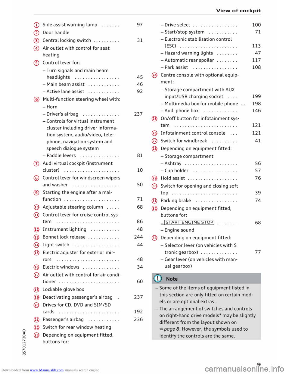
Side assist warning lamp
@ Door handle
®
@ Central
locking switch
Air outlet with control for seat
heating
® Control lever for:
- Turn signals and main beam
headlights ................ .
- Main beam assist ...........
.
- Active lane assist
........... .
@ Multi-function steering wheel with:
-Horn
- Driver's airbag ............. .
- Controls for virtual instrument
cluster including driver informa
tion system, audio/video, tele
phone, navigation system and
speech dialogue system
- Paddle levers .............. .
0 Audi virtual cockpit (instrument
cluster) .................... .
® Control lever for windscreen wipers
and washer ................. .
® Starting the
engine
after a mal-
function .................... .
@ Adjustable steering column .... .
@ Control lever for cruise control sys-
tem ....................... .
@ Instrument lighting .......... .
@ Bonnet lock release ........... .
� Light switch ................. .
@ Electric adjuster for exterior mir-
rors .......................
.
@ Electric windows ............. .
@ Air outlet with control for air condi-
tioner ...................... .
@ Lockable glove box
@ Deactivating passenger's airbag
@ Drives for CD, DVD and SIM/SD
cards ...................... .
@ Passenger's airbag ........... .
@ Switch for rear window heating
@ Depending on equipment fitted,
buttons for: 97
31
45
46
92
237
81
10 so
71
68
86 48
244
44
48 34
60
237
192
236 View
of cockpit
- Drive select ................ .
- Start/stop system .......... .
- Electronic stabilisation control
(ESC) ..................... .
- Hazard warning lights
- Automatic rear spoiler ....... .
- Park assist ................ .
(8 Centre console with optional equip
ment:
- Storage compartment with AUX
input/USB charging socket ....
- Multimedia box for mobile phone
-Audi phone box ............ .
@ On/off button for infotainment sys-
tem ....................... .
@ Infotainment control console .. .
@ Switch for windbreak ......... .
@ Depending on equipment fitted:
- Storage compartment
-Ashtray ................... .
- Cup holder ................ .
@) Hold assist .................. .
@ Switch for opening and closing soft
top ........................ .
@ Parking brake ............... .
@ Depending on equipment fitted,
buttons for:
-!START ENGINE STOP!
....... .
- Engine sound
@ Depending on equipment fitted:
- Selector lever (on vehicles with S
tronic gearbox) ............. .
- Gear lever (on vehicles with man
ual gearbox)
(© Note 100
71
113 47
117
108
199
198
146
121
121
41
56
57
76
39
74
68
77
- Some of the items of equipment listed in
this section are only fitted on certain mod
els or are optional extras.
- The arrangement of switches and controls
on right-hand drive models* may be slightly
different from the layout shown on
¢ page 8. However, the symbols used to
identify the controls are the same.
9
Page 15 of 306
Downloaded from www.Manualslib.com manuals search engine 0
N
,.....
N
......
0
,.....
Vl
CX) Instruments
and warning/indicator lamps
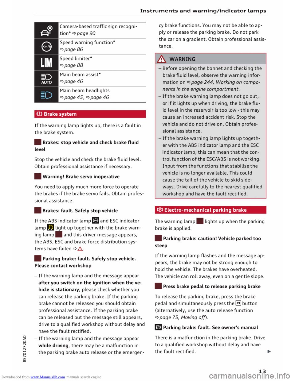
Camera-based traffic sign recogni
tion* ¢ page 90
Speed warning function*
¢page 86
Speed limiter*
¢page 88
Main beam assist*
¢page46
Main beam headlights
¢ page 45, ¢ page 46
(Q)) Brake system
If the warning lamp lights up, there is a fault in
the brake system.
• Brakes: stop vehicle and check brake fluid
Level
Stop the vehicle and check the brake fluid level.
Obtain professional assistance if necessary.
• Warning! Brake servo inoperative
You need to apply much more force to operate
the brakes if the brake servo fails. Obtain profes
sional assistance .
• Brakes: fault. Safely stop vehicle
If the ABS indicator lamp liJ and ESC indicator
lamp DJ
light up together with the brake warn
ing lamp .
and this driver message appears,
the ABS, ESC and brake force distribution sys
tems have failed ¢ .&. .
• Parking brake: fault. Safely stop vehicle.
Please contact workshop
- If the warning lamp and the message appear
after you switch on the ignition when the ve
hicle is stationary, please check whether you
can release the parking brake. If the parking
brake cannot be released you should obtain
professional assistance. If the parking brake
can be released but the message still appears,
drive to a qualified workshop without delay and
have the fault rectified.
- If the warning lamp and the message appear
while driving, there may be a malfunction in
the parking brake auto release or the emergen- cy
brake functions. You may not be able to ap
ply or release the parking brake. Do not park
the car on a gradient. Obtain professional assis
tance.
A WARNING
- Before opening the bonnet and checking the
brake fluid level, observe the warning infor
mation on ¢ page 244, Working on compo
nents in the engine compartment.
- If the brake warning lamp does not go out,
or if it lights up when driving, the brake flu
id level in the reservoir is too low -this may
cause an increased accident risk. Stop the
vehicle and do not drive on. Obtain profes
sional assistance.
- If the brake warning lamp lights up togeth
er with the ABS indicator lamp and the ESC
indicator lamp, this can mean that the con
trol function of the ESC/ABS is not working.
Input from the functions that stabilise the
vehicle is no longer available. This could
cause the tail of the vehicle to skid side
ways. Drive carefully to the nearest qualified
workshop and have the fault rectified.
C®) Electro-mechanical parking brake
The warning lamp.
lights up when the parking
brake is applied.
• Parking brake: caution! Vehicle parked too
steep
If the warning lamp flashes and the message ap
pears, the brake may not be strong enough to
hold the vehicle. The brakes have overheated.
The vehicle can roll away, even on a gentle slope.
• Press brake pedal to release parking brake
To release the parking brake, press the brake
pedal and simultaneously press the� button
(alternatively, use the auto release function
¢ page 75, Moving off).
rlJ Parking brake: fault. See owner's manual
There is a malfunction in the parking brake. Drive
to a qualified workshop without delay and have
the fault rectified.
..,.
13
Page 16 of 306
Downloaded from www.Manualslib.com manuals search engine Instruments
and warning/indicator Lamps
rlJ Parking brake: fault. Safely stop vehicle.
Please contact workshop
There is a malfunction in the parking brake. Drive
to a qualified workshop soon and have the fault
rectified.
[i] Hold assist: only available when door is
closed and engine is running
If this message appears, make sure that the door
is closed, the seat belt is buckled and the engine
is running.
[i] Hold assist: unavailable
If this message appears, the system require
ments have not been met.
� Please release parking brake
If this message appears, release the parking
brake.
� Parking brake auto release: unavailable
If this message appears, press the brake pedal
and then release the parking brake.
� Parking brake: caution! Vehicle parked too
steep
If the warning Lamp flashes and the message ap
pears, the brake may not be strong enough to
hold the vehicle. The brakes have overheated.
The vehicle can roll away, even on a gentle slope.
� Parking brake is applied
If this message appears, press the brake pedal
and then release the parking brake as necessary.
(D Note
For further information on the parking brake
refer to¢ page 74.
_t Cooling system
• Switch off engine and check coolant level.
See owner's manual
The coolant Level is too Low.
Switch off the engine and do not drive on. Check
the coolant Level¢ page 249.
14 -
If the coolant Level is too Low, add more coolant
¢ page 249. Do not drive on until the warning
Lamp has gone out.
• Coolant temperature: too high. Let engine
run with vehicle stationary
Let the engine cool down by running it at idling
speed for a few minutes until the warning Lamp
goes out.
- Do not drive on if the warning Lamp does not
disappear. Obtain professional assistance.
A WARNING
- Never open the bonnet if you can see or hear
steam or coolant escaping from the engine
compartment; there is a risk of being scal
ded. Wait until you can no Longer see or
hear escaping steam or coolant.
- The engine compartment of any motor vehi
cle is a dangerous place. Before carrying out
any work in the engine compartment, switch
off the engine and allow it to cool down.
Please observe the important safety warn
ings ¢ page 244, Working on components
in the engine compartment.
CD CAUTION
Do not drive on if the warning Lamp. Lights
up; otherwise there is a risk of engine dam
age.
9::::r. Engine oil pressure
• Switch off engine. Oil pressure too low
Switch off the engine and do not drive on. Check
the engine oil Level ¢ page 247.
- If the engine oil Level is too Low, add more oil
¢ page 247. Do not drive on until the warning
Lamp has gone out .
- If the engine oil Level is OK and the warning
Lamp is flashing, switch off the engine and do
not drive on. Obtain professional assistance.
Page 19 of 306
Downloaded from www.Manualslib.com manuals search engine 0
N
,.....
N
......
0
,.....
Vl
CX) Instruments
and warning/indicator lamps
Pedestrian protection system
If the indicator Lamp El Lights up or flashes and
the bonnet is in a raised position, the pedestrian
protection system has been triggered. Please re
fer to¢ page 228, Pedestrian protection sys
tem.
.&_ WARNING
Have the safety systems examined without
delay; otherwise they may fail to trigger in an
accident -this could result in serious or possi
bly fatal injury.
� Engine management
Applies to: vehicles with petrol engine
If the indicator Lamp II Lights up, there is a fault
in the engine management system.
Drive slowly to a qualified workshop without de
lay and have the engine checked.
W Engine management (diesel engine)
Applies to: vehicles with diesel engine
If the indicator Lamp II Lights up when the igni
tion is switched on, the glow plugs are preheat
ing.
If the indicator lamp flashes while the vehicle is
moving, there is a fault in the engine manage
ment system.
Drive slowly to a qualified workshop without de
lay and have the fault rectified.
G Emission control system
If the indicator Lamp II Lights up or flashes, a
fault has occurred which can reduce the quality of
the exhaust gas and damage the catalytic con
verter.
Drive slowly to a qualified workshop without de
lay and have the fault rectified.
@.> Diesel particulate filter
Applies to: vehicles with diesel engine and diesel particulate
filter
C Particulate filter: fault. See owner's manual The
diesel particulate filter requires regenera
tion. You can assist the self-cleaning function of
the filter by driving as follows:
Drive at a speed of at Least 60 km/h for about
15 minutes in 4th or 5th gear, or with the selec
tor lever in position Son vehicles with automatic
gearbox. Keep the engine speed at about
2000 rpm. As a result of the increase in tempera
ture, the soot in the filter will be burned off. The
indicator lamp will go out once the cleaning proc
ess has been completed successfully.
If the indicator Lamp does not go out, drive to a
qualified workshop without delay and have the
fault rectified.
.&_ WARNING
It is essential that you adjust your speed to
suit the weather, road, terrain and traffic con
ditions. The recommended driving speed
must never Lead to the driver disregarding the
traffic reg u Lations.
@ Note
For more information about the diesel partic
ulate filter, refer to ¢page 244.
!?') Engine speed governing
Applies to: vehicles with engine speed governing
(m Max. engine speed: XXXX rpm
The engine speed will automatically be governed
to the speed displayed in the driver information
system. This protects the engine from overheat
ing.
The rev Limiter is deactivated as soon as the en
gine temperature is no Longer within the critical
range and you have taken your foot off the accel
erator.
If the rev Limiter has been activated because of a
fault in the engine management system, the in
dicator Lamp II will also Light up. Make sure that
the engine speed does not exceed the speed dis
played in the driver information system, for ex
ample when shifting down a gear. Drive to a
qualified workshop without delay and have the
fault rectified.
17
Page 31 of 306
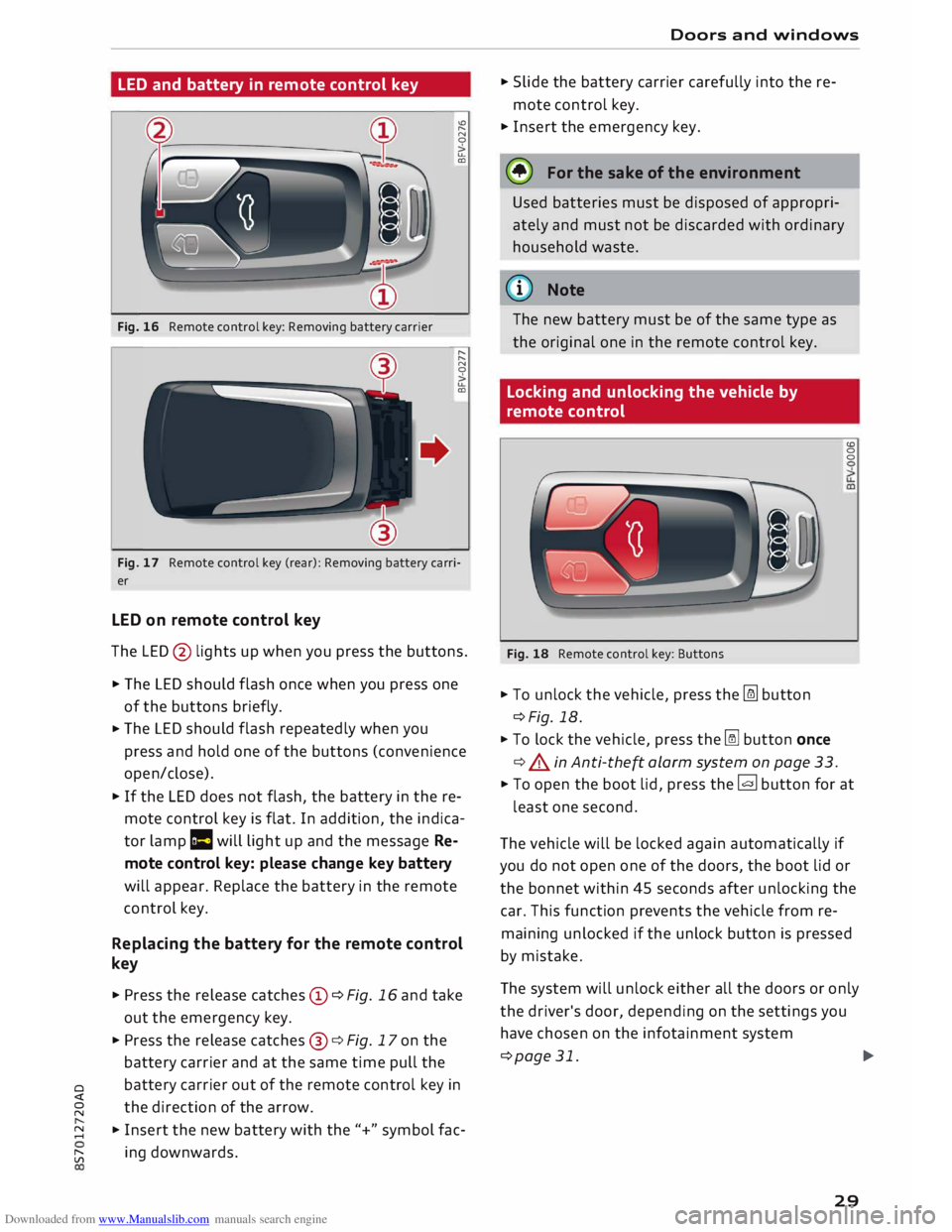
Downloaded from www.Manualslib.com manuals search engine LED
and battery in remote control key
Fig. 16 Remote control key: Removing battery carrier "'
"
N
0
>
u..
CD
"
"
N
0
>
u..
CD
Fig. 17 Remote control key (rear): Removing battery carri
er
LED on remote control key
The LED @ lights up when you press the buttons.
� The LED should flash once when you press one
of the buttons briefly.
� The
LED should flash repeatedly when you
press and hold one of the buttons (convenience
open/close).
� If
the LED does not flash, the battery in the re
mote control key is flat. In addition, the indica
tor lamp la will light up and the message Re
mote control key: please change key battery
will appear. Replace the battery in the remote
control key.
Replacing the battery for the remote control
key
� Press the release catches© ¢Fig. 16 and take
out the emergency key.
� Press the release catches@¢ Fig. 17 on the
battery carrier and at the same time pull the
o battery
carrier out of the remote control key in
direction of the arrow.
� �
Insert the new battery with the"+" symbol fac-
[;:j ing
downwards. Doors
and windows
� Slide the battery carrier carefully into the re
mote control key.
� Insert the emergency key.
@ For the sake of the environment
Used batteries must be disposed of appropri
ately and must not be discarded with ordinary
household waste.
@ Note
The new battery must be of the same type as
the original one in the remote control key.
Locking and unlocking the vehicle by
remote control
Fig. 18 Remote control key: Buttons
� To unlock the vehicle, press the [m button
¢Fig. 18.
� To lock the vehicle, press the� button once
¢ .&. in Anti-the� alarm system on page 33. (0
0
0
� To open the boot lid, press the� button for at
least one second.
The vehicle will be locked again automatically if
you do not open one of the doors, the boot lid or
the bonnet within 45 seconds after unlocking the
car. This function prevents the vehicle from re
maining unlocked if the unlock button is pressed
by mistake.
The system will unlock either all the doors or only
the driver's door, depending on the settings you
have chosen on the infotainment system
¢page 31.
.,..
29
Page 34 of 306
Downloaded from www.Manualslib.com manuals search engine Doors
and windows
Locking and unlocking the doors manually
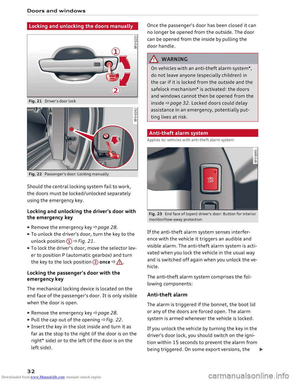
Fig. 21 Driver's door lock
Fig. 22 Passenger's door: Locking manually
Should the central locking system fail to work,
the doors must be locked/unlocked separately
using the emergency key.
Locking and unlocking the driver's door with
the emergency key
... Remove the emergency key c::> page 28.
.., To unlock the driver's door, turn the key to the
unlock position © c::>Fig. 21.
.., To lock the driver's door, move the selector lev
er to position P (automatic gearbox) and turn
the key to the lock position @ once c::> .,&. .
Locking the passenger's door with the
emergency key
The mechanical locking device is located on the
end face of the passenger's door. It is only visible
when the door is open.
... Remove the emergency key c::>page 28.
... Pull the cap out of the opening c::>Fig. 22 .
... Insert the key in the slot inside and turn it as
far as the stop to the right (if the door is on the
right* side) or to the left (if the door is on the
left side).
32 Once
the passenger's door has been closed it can
no longer be opened from the outside. The door
can be opened from the inside by pulling the
door handle.
A WARNING
On vehicles with an anti-theft alarm system*,
do not leave anyone (especially children) in
the car if it is locked from the outside and the
safelock mechanism* is activated: the doors
and windows cannot then be opened from the
inside c::> page 32. Locked doors could delay
assistance in an emergency, potentially put
ting lives at risk.
Anti-theft alarm system
Applies to: vehicles with anti-theft alarm system
Fig. 23 End face of (open) driver's door: Button for interior
monitor/tow-away protection
If the anti-theft alarm system senses interfer
ence with the vehicle it triggers an audible and
visible alarm. The anti-theft alarm system is acti
vated when you lock the vehicle in the usual way
and is switched off again when you unlock the ve
hicle.
The anti-theft alarm system comprises the fol
lowing components:
Anti-theft alarm
The alarm is triggered if the bonnet, the boot lid
or any of the doors are forced open. The alarm
system is armed whenever the vehicle is locked .
If you unlock the vehicle by turning the key in the
driver's door lock, you should switch on the igni
tion within 15 seconds to prevent the alarm from
being triggered. On some export versions, the ..,.
Page 53 of 306
Downloaded from www.Manualslib.com manuals search engine 0
N
,.....
N
......
0
,.....
Vl
CX) -
The windscreen washer jets are heated*
when the ignition is switched on if the out
side temperature is low.
- If you stop briefly, e.g. at traffic lights, the
wiper speed setting will automatically be re
duced by one level.
Cleaning windscreen wiper blades
Clean the wiper blades if the wipers leave smear
ing on the glass. Clean the wiper blades using a
soft cloth and a glass cleaning solution.
11- Set the wiper arms to the service position
¢page 51.
11- Lift the wiper arms away from the glass.
A WARNING
Dirty wiper blades can impair the driver's view
- risk of accident!
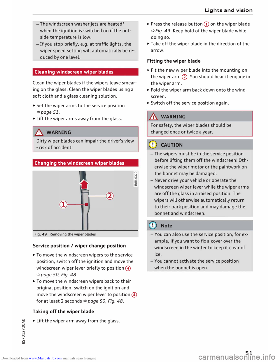
Changing the windscreen wiper blades
Fig. 49 Removing the wiper blades
Service position / wiper change position
11- To move the windscreen wipers to the service
position, switch off the ignition and move the
windscreen wiper lever briefly to position ©
¢ page 50, Fig. 48. a,
,._.
(')
0
0)
CD
11- To move the windscreen wipers back to their
original position, switch on the ignition and
move the windscreen wiper lever to position ©
for at least 2 seconds¢ page 50, Fig. 48.
Taking off the wiper blade
11- Lift the wiper arm away from the glass. Lights
and vision
11- Press the release button (Don the wiper blade
¢ Fig. 49. Keep hold of the wiper blade while
doing so.
11- Take off the wiper blade in the direction of the
arrow.
Fitting the wiper blade
11- Fit the new wiper blade into the mounting on
the wiper arm@. You should hear it engage in
the wiper arm.
11- Fold the wiper arm back down onto the wind
screen.
11- Switch off the service position again.
A WARNING
For safety, the wiper blades should be
changed once or twice a year.
CD CAUTION
- The wipers must be in the service position
before lifting them off the windscreen! Oth
erwise the wiper motor or the paintwork on
the bonnet may be damaged.
- Never drive your vehicle or operate the
windscreen wiper lever while the wiper arms
are off the glass in a raised position. The
wipers will otherwise automatically return
to their park position and may damage the
bonnet and windscreen.
(D) Note
- You can also use the service position, for ex
ample, if you want to fix a cover over the
windscreen in the winter to keep it clear of
ice.
- You cannot activate the service position
when the bonnet is open.
51
Page 73 of 306
Downloaded from www.Manualslib.com manuals search engine !START
E
NGIN E
STOP!
button. Put the selector
lever in position P; otherwise the vehicle can roll
away. If the lever is not in position P you will not
be able to lock the vehicle using the locking sen
sor on the door handle or the convenience key.
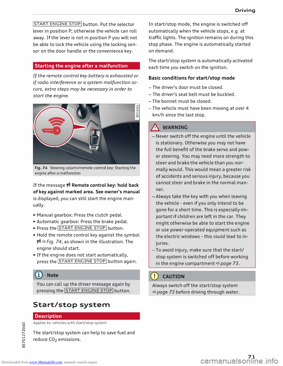
Starting the engine after a malfunction
If the remote control key battery is exhausted or
if radio interference or a system malfunction oc
curs, extra steps may be necessary in order to
start the engine.
Fig. 74 Steering column/remote control key: Starting the
engine after a malfunction
If the message t>>) Remote control key: hold back
of key against marked area. See owner's manual
is displayed, you can still start the engine man
ually.
� Manual gearbox: Press the clutch pedal.
� Automatic gearbox: Press the brake pedal.
� Press the !START
ENGINE STOP!
button.
� Hold the remote control key against the symbol
y>>) ¢Fig. 74, as shown in the illustration. The
engine should start.
� If the engine does not start automatically,
press the !START
E
NGINE STOP!
button again.
@ Note
You can call up the driver message again by
pressing the !START
ENGINE STOP!
button.
Start/stop system Description
0 Applies
to: vehicles with start/stop system
� The start/stop system can help to save fuel and
8 reduce CO
2 emissions.
"
Vl Driving
In start/stop mode, the engine is switched off
automatically when the vehicle stops, e.g. at
traffic lights. The ignition remains on during this
stop phase. The engine is automatically started
on demand.
The start/stop system is automatically activated
each time you switch on the ignition.
Basic conditions for start/stop mode
- The driver's door must be closed.
- The driver's seat belt must be buckled.
- The bonnet must be closed.
- The vehicle must have been moving at over 4
km/h since the last stop.
A WARNING
- Never switch off the engine until the vehicle
is stationary. Otherwise you may not have
the full benefit of the brake servo and pow
er steering. You may need more strength to
steer and brake the vehicle than you nor
mally would. This would mean a greater risk
of accidents and serious injury, because you
cannot steer and brake in the normal man
ner.
- Always take the key with you when leaving
the vehicle -even if you only intend to be
gone for a short time. This is especially im
portant if children are left in the car. They
might otherwise be able to start the engine
or use power-operated equipment such as
the electric windows -this could lead to in
juries.
- To avoid injury, make sure that the start/
stop system is switched off before working
in the engine compartment ¢page 73.
CD CAUTION
Always switch off the start/stop system
¢page 73 before driving through water.
71
Page 80 of 306
Downloaded from www.Manualslib.com manuals search engine Driving
while the engine is running, you must apply
the parking brake and engage the parking
lock P.
- To avoid accidents, apply the parking brake
and put the selector lever in position P be
fore opening the bonnet and working on the
vehicle with the engine running. Please ob
serve the important safety warnings
¢ page 244, Working on components in
the engine comportment.
Ct) Note
- Drive select: You can select the sport pro
gram for gear changes by activating the dy
namic mode. The infotainment display will
show S instead of D.
- If the lever is moved accidentally to N when
driving, take your foot off the accelerator
and let the engine speed drop to idling be
fore selecting Dor S again.
- It is not possible to move the selector lever
out of position P if the electrical power sup
ply fails. In this case, the selector lever can
be released manually. Left-hand drive
vehicles ¢page 84, right-hand drive
vehicles ¢page 85.
Selector lever lock
Applies to: vehicles with automatic gearbox
The selector Lever Lock prevents gears from being
engaged inadvertently, so that the vehicle is not
set in motion unintentionally.
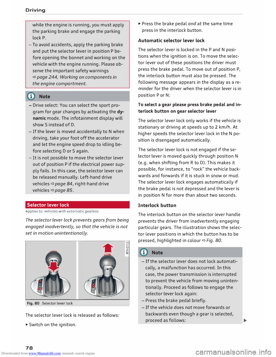
Fig. 80 Selector lever lock
The selector lever lock is released as follows:
• Switch on the ignition.
78 •
Press the brake pedal and at the same time
press in the interlock button.
Automatic selector lever lock
The selector lever is locked in the P and N posi
tions when the ignition is on. To move the selec
tor lever out of these positions the driver must
press the brake pedal. To move out of position P,
the interlock button must also be pressed. The
following message appears in the display as a re
minder for the driver when the selector lever is in
position P or N:
To select a gear please press brake pedal and in
terlock button on gear selector lever
The selector lever lock only works if the vehicle is
stationary or driving at speeds up to 2 km/h. At
higher speeds the selector lever lock in the N po
sition is disengaged automatically.
The selector lever lock is not engaged if the se
lector lever is moved quickly through position N
(e.g. when shifting from R to D). This makes it
possible, for instance, to "rock" the vehicle back
wards and forwards if it is stuck in snow or mud.
The selector lever lock engages automatically if
the brake pedal is not depressed and the lever is
in position N for more than about two seconds.
Interlock button
The interlock button on the selector lever handle
prevents the driver from inadvertently engaging
particular gears. The illustration shows the selec
tor lever positions in which the button has to be
pressed, highlighted in colour¢ Fig. 80.
{(D) Note
- If the selector lever does not lock automati
cally, a malfunction has occurred. In this
case, the power transmission is interrupted
to prevent the vehicle from moving uninten
tionally. Proceed as follows to engage the
selector lever lock again:
- Press the brake pedal briefly.
- If the vehicle does not move forwards or
backwards even though a gear is selected,
proceed as follows:
Page 230 of 306
Downloaded from www.Manualslib.com manuals search engine Safe
driving
� Note
- The tyre pressure must be adjusted accord
ing to the Load the vehicle is carrying
¢page 256.
-Air circulation in the vehicle helps reduce
fogging of the windows. Used air escapes
through ventilation slots in the rear of the
vehicle. Make sure that these ventilation
slots are not obstructed.
- Suitable belts for securing Loads to the fas
tening rings* are commercially available.
Fastening rings
Unsecured Loads are a hazard to all vehicle occu
pants.
AUDI
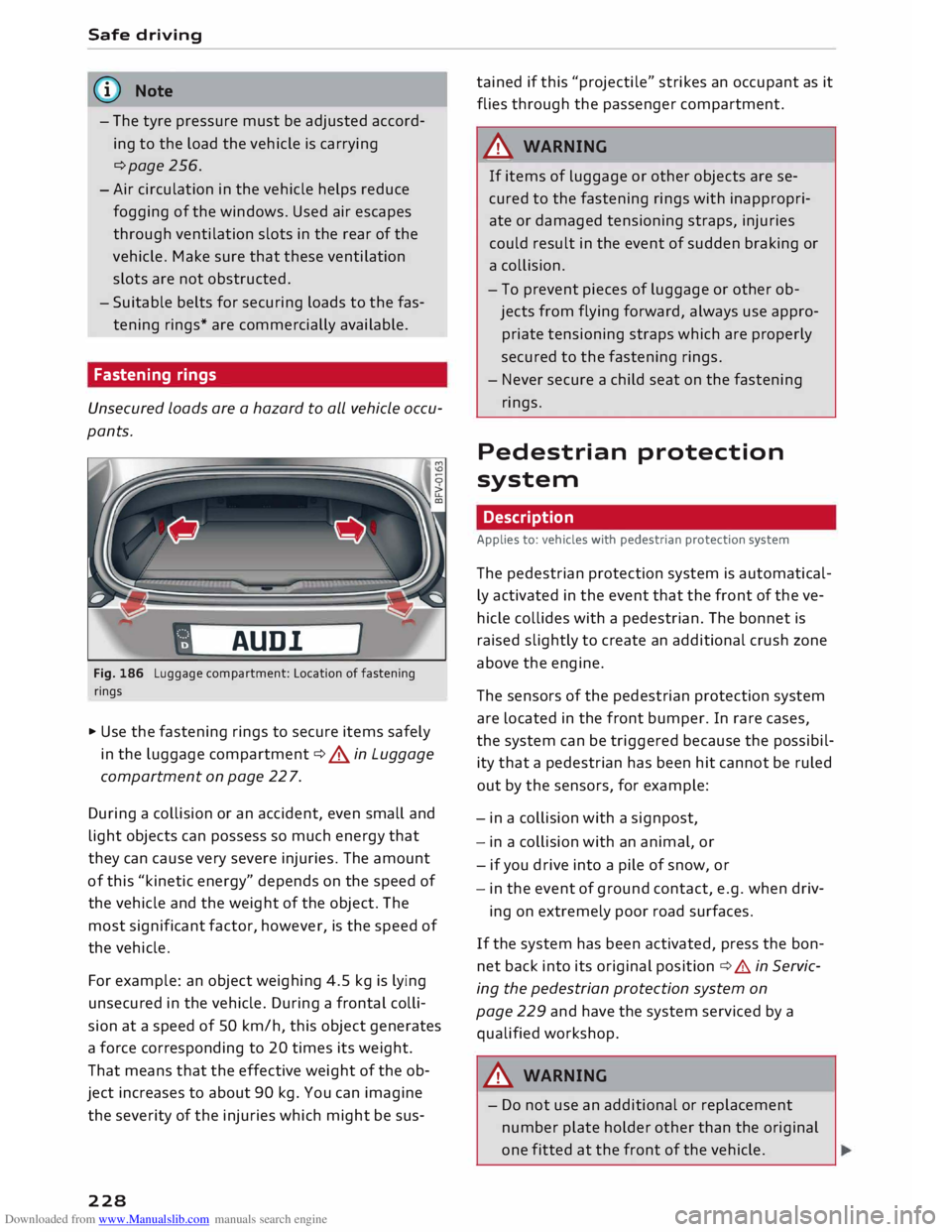
Fig. 186 Luggage compartment: Location of fastening
rings
� Use the fastening rings to secure items safely
in the Luggage compartment ¢.&. in Luggage
compartment on page 22 7.
During a collision or an accident, even small and
Light objects can possess so much energy that
they can cause very severe injuries. The amount
of this "kinetic energy" depends on the speed of
the vehicle and the weight of the object. The
most significant factor, however, is the speed of
the vehicle.
For example: an object weighing 4.5 kg is Lying
unsecured in the vehicle. During a frontal colli
sion at a speed of 50 km/h, this object generates
a force corresponding to 20 times its weight.
That means that the effective weight of the ob
ject increases to about 90 kg. You can imagine
the severity of the injuries which might be sus-
228 tained
if this "projectile" strikes an occupant as it
flies through the passenger compartment.
A WARNING
If items of Luggage or other objects are se
cured to the fastening rings with inappropri
ate or damaged tensioning straps, injuries
could result in the event of sudden braking or
a collision.
- To prevent pieces of Luggage or other ob
jects from flying forward, always use appro
priate tensioning straps which are properly
secured to the fastening rings.
- Never secure a child seat on the fastening
rings.
Pedestrian protection
system
Description
Applies to: vehicles with pedestrian protection system
The pedestrian protection system is automatical
ly activated in the event that the front of the ve
hicle collides with a pedestrian. The bonnet is
raised slightly to create an additional crush zone
above the engine.
The sensors of the pedestrian protection system
are Located in the front bumper. In rare cases,
the system can be triggered because the possibil
ity that a pedestrian has been hit cannot be ruled
out by the sensors, for example:
- in a collision with a signpost,
- in a collision with an animal, or
- if you drive into a pile of snow, or
- in the event of ground contact, e.g. when driv-
ing on extremely poor road surfaces.
If the system has been activated, press the bon
net back into its original position ¢.&. in Servic
ing the pedestrian protection system on
page 229 and have the system serviced by a
qualified workshop.
A WARNING
- Do not use an additional or replacement
number plate holder other than the original
one fitted at the front of the vehicle.