ECU AUDI TT ROADSTER 2017 Owners Manual
[x] Cancel search | Manufacturer: AUDI, Model Year: 2017, Model line: TT ROADSTER, Model: AUDI TT ROADSTER 2017Pages: 314, PDF Size: 76.54 MB
Page 6 of 314
Table of content s
Safety belts . . . . . . . . . . . . . . . . . . . . . . . . 192
Safety belt tensioner . . . . . . . . . . . . . . . . . 194
Airbag system ... . ...... ... .. .. ... 19 6
I mportant info rmation . . . . . . . . . . . . . . . 196
F ront airbags . . . . . . . . . . . . . . . . . . . . . . . 200
Mon itoring the Advanced Airbag System . 207
Knee airbags........................ 212
Side airbags . . . . . . . . . . . . . . . . . . . . . . . . 214
Ch ild safety . . . . . . . . . . . . . . . . . . . . . . 218
Important information . . . . . . . . . . . . . . . 218
Ch ild seats . . . . . . . . . . . . . . . . . . . . . . . . . 223
Secur ing ch ild seats . . . . . . . . . . . . . . . . . . 227
Add it io nal info rmation . . . . . . . . . . . . . . . 230
Maintenanc e and Care . . . . . . . . . . . 23 1
Checking and Filling . . . . . . . . . . . . . 23 1
F ue l... .. .. .. .. ... .......... .... .. . 23 1
Refueling . . . . . . . . . . . . . . . . . . . . . . . . . . 232
E ng ine compartment . . . . . . . . . . . . . . . . . 235
Eng ine oi l .... .. ... .. ..... ... .. .. ... 237
Cooling system . . . . . . . . . . . . . . . . . . . . . . 241
Brake fluid . . . . . . . . . . . . . . . . . . . . . . . . . 242
Battery . . . . . . . . . . . . . . . . . . . . . . . . . . . . 243
W indshield washer system . . . . . . . . . . . . 244
Service interval display . . . . . . . . . . . . . . . 245
Wheels ... .. ... ............ .... .. . 246
Wheels and Tires . . . . . . . . . . . . . . . . . . . . 246
Tire pressure monitoring system 263
Care and cleaning . . . . . . . . . . . . . . . . 266
General information . . . . . . . . . . . . . . . . . 266
Ca r washes . . . . . . . . . . . . . . . . . . . . . . . . . 266
C lea ning and care information . . . . . . . . . 267
P lacing your veh icle o ut of se rvice 27 1
Troubleshooting . . . . . . . . . . . . . . . . . 27 2
Emergency assistance . . . . . . . . . . . 272
T runk es cape l atch . . . . . . . . . . . . . . . . . . . 27 2
G eneral informa tion . . . . . . . . . . . . . . . . . 272
Equipment . . . . . . . . . . . . . . . . . . . . . . . . . 272
Tire mobility k it . . . . . . . . . . . . . . . . . . . . . 273
Replac ing whee ls . . . . . . . . . . . . . . . . . . . . 275
Spare tire . . . . . . . . . . . . . . . . . . . . . . . . . . 279
4
Fuses and bulbs . . . . . . . . . . . . . . . . . . 281
E lectrica l fuses . . . . . . . . . . . . . . . . . . . . . . 281
Bu lbs. . . . . . . . . . . . . . . . . . . . . . . . . . . . . . 283
Emergency situations . . . . . . . . . . . . 2 8 4
Genera l . . . . . . . . . . . . . . . . . . . . . . . . . . . . 284
Start ing by push ing or tow ing . . . . . . . . . . 284
Start ing with jumper cables . . . . . . . . . . . 284
Use o f jumper cables . . . . . . . . . . . . . . . . . 28S
T owing with a tow truck . . . . . . . . . . . . . . 286
Raising the vehicle . . . . . . . . . . . . . . . . . . . 288
Accessories and technical data . . 290
Technical data . . . . . . . . . . . . . . . . . . . . 290
Vehicle spec ificat ions . . . . . . . . . . . . . . . . 290
Weights . . . . . . . . . . . . . . . . . . . . . . . . . . . 290
D imens ions. . . . . . . . . . . . . . . . . . . . . . . . . 291
Capaci ties . . . . . . . . . . . . . . . . . . . . . . . . . . 291
Gasoline engines . . . . . . . . . . . . . . . . . . . . 292
Consumer information and
technical data . . . . . . . . . . . . . . . . . . . .
293
Consumer information . . . . . . . . . . 293
Warranty coverages . . . . . . . . . . . . . . . . . . 293
Operat ing your vehicle outside the U.S.A.
or Canada . . . . . . . . . . . . . . . . . . . . . . . . . . 293
Audi Service Repair Manuals and Lite rat ure . . . . . . . . . . . . . . . . . . . . . . . . . . 293
Maintenance. . . . . . . . . . . . . . . . . . . . . . . . 293
Accessor ies a nd techn ica l changes 295
Index .......... ... ............. ... 297
Page 25 of 314
CD
CD
.... N
" N .... 0
" V, co
Tachometer
The tachometer displays the engine speed in rev
olutions per minute (RPM) .
The beginning of the red zone in the tachometer
indicates the maximum permissible engine speed
for all gears once the engine has been broken in
and when it is warm. Before reaching the red
zone, you should shift into the next higher gear,
choose the Dor S selector lever position, or re
move your foot from the accelerator pedal.
@ Note
The needle in the tachometer may only be in
the red area of the gauge for a short per iod of
time or there is a risk of damaging the engine .
The location where the red zone begins varies
depending on the engine.
@) For the sake of the environment
Upshifting early helps you to save fuel and re
duce operating noise.
Odometer
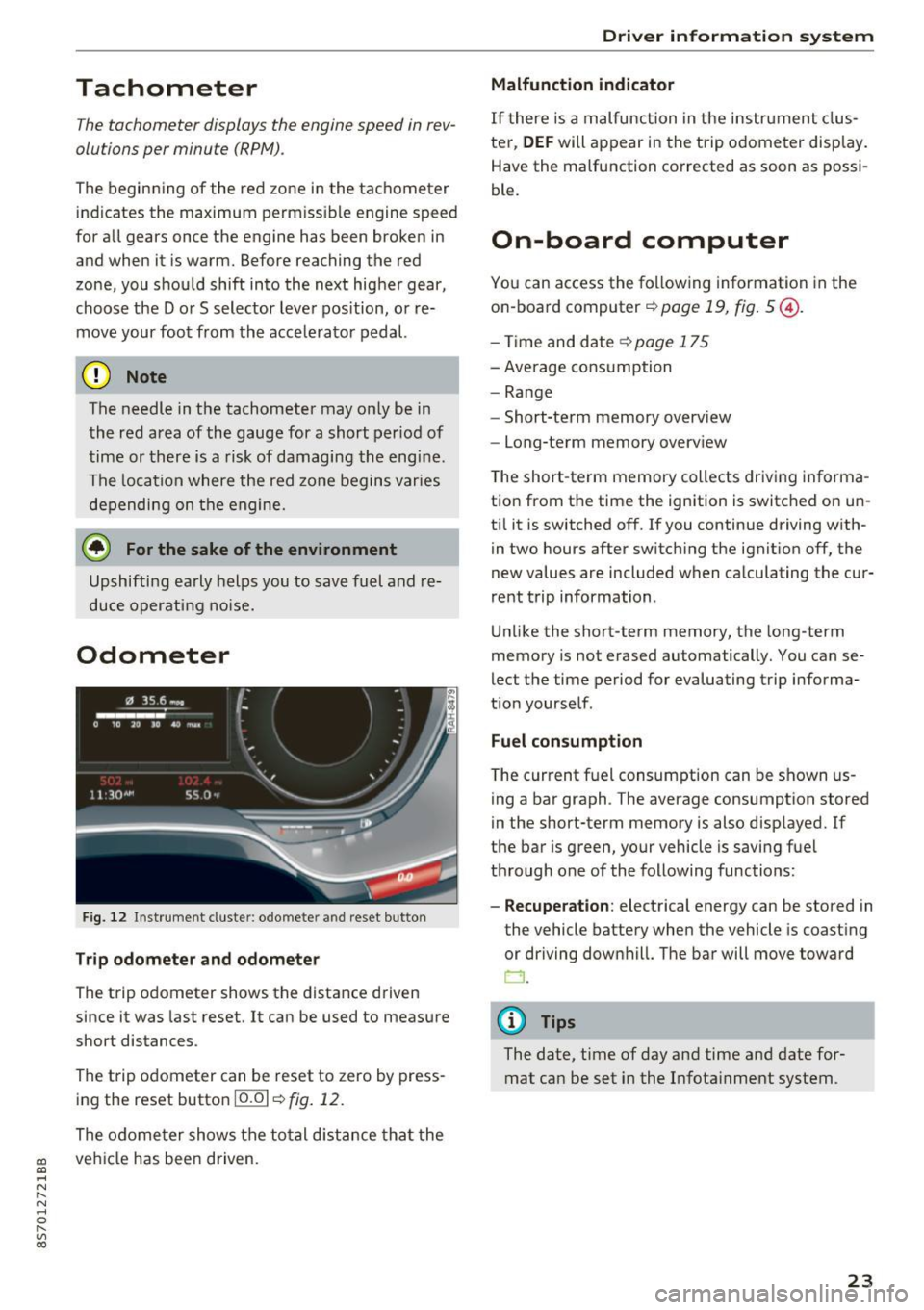
Fig. 12 Instrument cluste r: odomete r and reset button
Trip odometer and odometer
The trip odometer shows the distance driven
since it was last reset . It can be used to measure
short distances .
The trip odometer can be reset to zero by press ing the reset button 10.01
r=> fig. 12.
The odometer shows the total d istance that the
veh icle has been driven.
Driver in forma tion system
Malfunction indicator
If there is a malfunction in the instrument clus
ter,
DEF will appear in the trip odometer disp lay.
Have the malfunction corrected as soon as possi
ble.
On-board computer
You can access the following information in the
on-board computer
r=> page 19, fig . 5 @ .
-Time and date ~page 175
-Average consumption
-Range
- Short-term memory overv iew
- Long-term memory overview
The short -term memory collects driving informa
tion from the time the ignition is switched on un
til it is switched off. If you continue driving with·
in two hours after switching the ignition off, the
new values are included when calculating the cur
rent trip information .
Unlike the short-term memory, the long-term
memory is not erased automatically. You can se
lect the time period for evaluating trip informa
tion yourself .
Fuel consumption
The current fuel consumption can be shown us
ing a bar graph . The average consumption stored
in the short-term memory is also displayed. If
the bar is green, your vehicle is saving fuel
through one of the following functions:
- Recuperation : electrical energy can be stored in
the vehicle battery when the vehicle is coasting or driving downhill. The bar will move toward
CJ .
(D Tips
The date, time of day and time and date for
mat can be set in the Infotainment system.
23
Page 30 of 314
Opening and clo sin g
Central locking switch
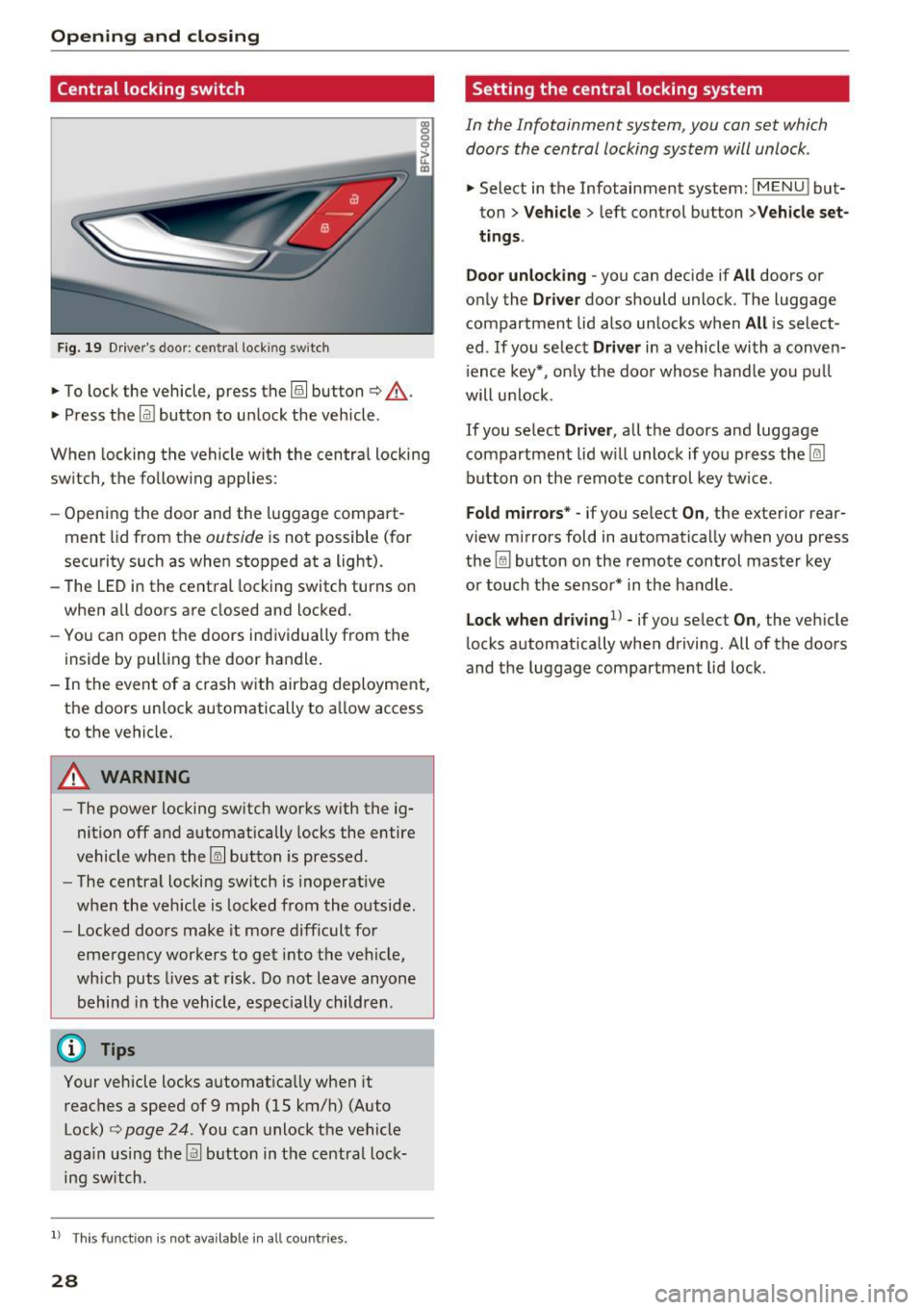
Fig. 19 D rive r's door : central lock ing switch
• To lock the vehicle, press the~ button c> .&,.
• Press t he !ill button to unlock the vehicle.
When locking the vehicle with the centra l locking
switch, the follow ing applies:
- Opening the door and the luggage compart
ment lid from the
outside is not possible (for
security such as when stopped at a light).
- The LED in the central locking switch turns on
when all doors are closed and locked.
- You can open the doors ind ividually from the
inside by pulling the door handle .
- In the event of a c rash with airbag deployment,
the doors unlock automat ically to a llow access
to the vehicle.
& WARNING
- The power locking sw itch works with the ig
nition off and automatically locks the entire
vehicle when the~ button is pressed.
- The centra l locking switch is inoperative
when the vehicle is locked from the outside.
- Locked doors make it more difficult for
emergency worke rs to get into t he vehicle,
wh ich puts lives at risk. Do not leave anyone
behind in the vehicle, especially children .
(D Tips
Your vehicle locks automatically when it
reaches a speed of 9 mph (15 km/h) (Auto Lock)
c> page 24 . You can unlock the vehicle
aga in using the
!ill b utton in the central lock
ing sw itch.
l) Th is fun ctio n is not a vailab le in a ll coun tries.
28
Setting the central locking system
In the Infotainment system, you can set which
doors the central locking system will unlock .
• Select in the Infotainment system: IMENU ! but
ton>
V eh icle > left control button >Vehicle set
t ings.
Door unloc king -
you can decide if All doors or
only the
Dr ive r door should unlock . The luggage
compartment lid also unlocks when
All i s select
ed . If you select
D riv er in a vehicle with a conven
i ence key*, on ly the door whose handle you pu ll
will unlock .
If you se lect
Dri ver , all the doors and luggage
compartment lid w ill unlock if you press the
I@
button on the remote control key tw ice .
Fold m irrors* -if you select On, the exterior rear
view m irrors fold in automatically when you press
the ~ button on the remote control master key
or touch the sensor* in the handle.
Lock whe n driving1l -if you select On , the veh icle
locks automatically when driving. All of the doors
and the luggage compartment lid lock .
Page 33 of 314
CD
CD
.... N
" N ,-I 0 r--. V, co
@ Tips
-You can still open and close the windows for
approximately 10 minutes after turn ing the
ignition off. The power windows do not
switch off until the driver's door or front passenger's door has been opened.
- When opening the doors and when open
i ng/closing the power top, the windows au
tomatically lower approximately 10 mm.
Convenience opening/closing
All windows can be opened and closed at the
same time.
Convenience opening feature
• Press the Im button on the remote control key
until all windows reach the desired position.
Convenience closing feature
• Press the {D button on the remote control key
u nti l all windows are closed¢
A or
Convenience closing with the convenience
key*
• Touch the sensor* on the door handle long
enough until all windows and the power top*
are closed . Do not place your hand in the door
hand le when doing this.
Setting convenience opening in the
Infotainment system
• Select in the Infotainment system: !MENUI but
ton
> Vehicle> left control button >Vehicle set
tings .
To enable the convenience window opening func
tion, the
Long press to open windows function
must be switched
on.
.&_ WARNING
- Never close the windows or power top* care lessly or in an uncontrolled manner, be
cause this increases the risk of injury.
- For security reasons, the windows and the
power top* can only be opened and closed
with the remote control key at a maximum
distance of approximately 6 ft (2 m) away
Open ing and closing
from the vehicle . Always pay attention when
pressing the
Im button to close the w indows
and the power top* so that no one is
pinched. The closing process w ill stop im
mediately when the
Im button is released .
Correcting power window malfunctions
You can reactivate the one-touch up/down func
tion if it malfunctions.
• Pull the power window switch up until the win
dow is completely raised.
• Release the switch and pull it up aga in for at
least one second .
Garage door opener
(Homelink)
Description
Applies to : veh icles w ith garage door o pen er (Home link)
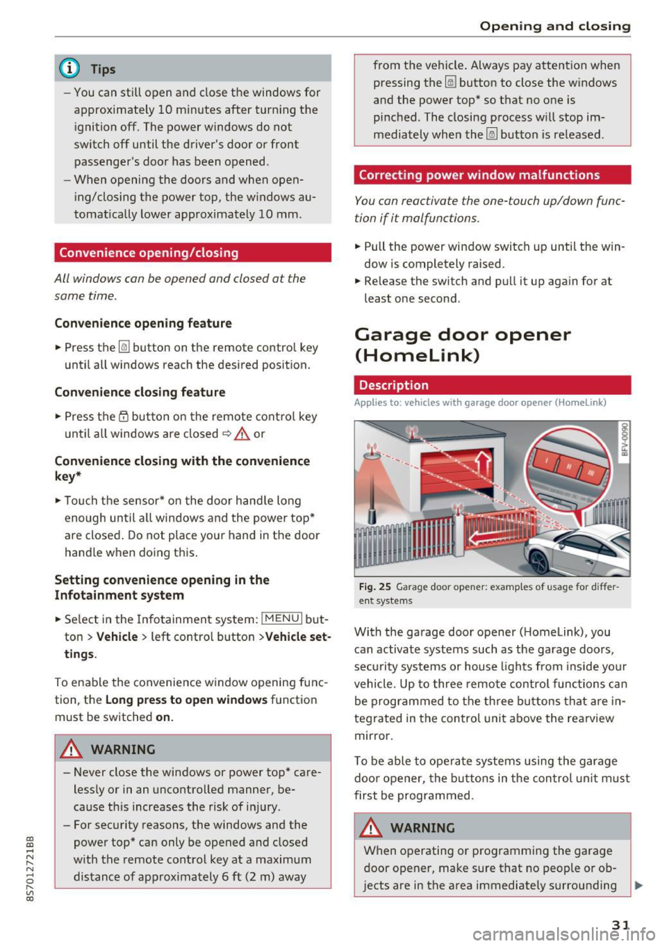
Fig. 25 Garage door opener: examples of usage for differ
ent systems
With the garage door opener ( Homelink), you
can activate systems such as the garage doors,
security systems or house lights from inside your
vehicle. Up to three remote control functions can
be programmed to the three buttons that are in
tegrated in the control unit above the rearview
mirror.
T o be able to operate systems using the garage
door opener, the buttons in the control unit must
first be programmed.
A WARNING ~
When operating or programming the garage
door opener, make sure that no people or ob
jects are in the area immediately surrounding ..,.
31
Page 34 of 314
Opening and closing
the equipment. Peop le can be injured or prop
erty can be damaged if struck when closing.
(D Tips
- For secu rity reasons, we recommend that
you clear the programmed buttons before
selling the vehicle.
- For additional information about Homelink,
v is it
www .homelink .com.
- For the Declaration of Conformity with the
provisions from the FCC in the United States
and Industry Canada, see¢
page 296 .
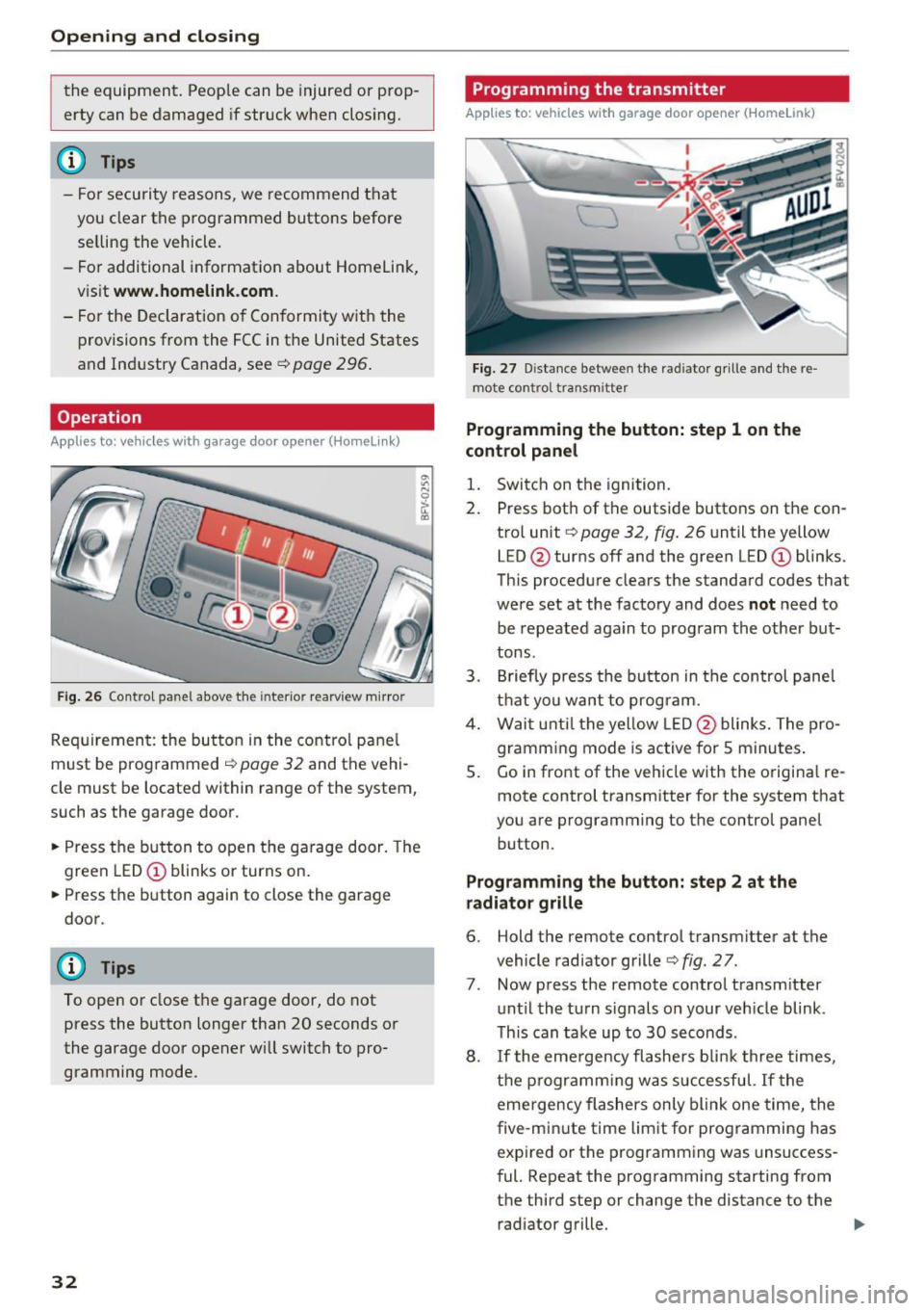
Operation
Applies to: ve hicles w ith garage doo r opener (Homeli nk)
Fig. 26 Contro l pa nel above the inter io r rearview mirror
Requirement: the but ton in the control panel
m ust be programmed
i:!> page 32 and the vehi
cle must be located within range of the system,
such as the garage door .
.. Press the button to open the garage door. The
green LED
CD blinks or turns on.
.. Press the button again to close the garage
door.
(D} Tips
To open or close the garage door, do not
press the button longer than 20 seconds or
the garage door opener w ill switch to pro
gramming mode.
32
Programming the transmitter
App lies to : vehicles wit h garage door o pener (Horne link)
Fig. 27 D istance between the rad iator g rille and the re
mote contro l transm itter
Programming the button: step 1 on the
control panel
1. Switch on the ignition.
2. Press both of the outside buttons on the con
trol unit ¢
page 32, fig. 26 until the yellow
LED @turns off and the green LED
CD blinks.
This procedure clears the standard codes that
were set at the factory and does
not need to
be repeated again to program the other but
tons.
3. Briefly press the button in the control panel
that you want to program.
4. Wait until the yellow LED@blinks. The pro
gramming mode is active for S minutes.
5. Go in front of the vehicle w ith the origina l re
mote control transmitter for the system that
you are programming to the control panel button .
Programming the button: step 2 at the
radiator grille
6. Hold the remote control transmitter at the
vehicle radiator grille¢
fig. 27.
7 . Now press the remote control transm itter
until the turn signals on your veh icle blink .
This can take up to 30 seconds .
8. If the eme rgency flashers blink three times,
the programming was successful. If the
emergency flashers only blink one time, the
five -min ute time limit for programming has
expired or the programming was unsuccess
ful. Repeat the programming starting from
the third step or change the distance to the radiator grille.
Page 38 of 314
Power top
Pow er top: op erati on curr ently not poss ible
I f the power top is operated continuo usly for a
long period of time, the overload protection acti
vates for approximate ly 15 to 30 minutes. You
can open or close the power top again after that .
Power top: operation currently not possible.
Engine mu st b e running
The power top is automatically deactivated if the
battery voltage is low. You can open or close the
power top again after starting the engine.
P ower top: op erati on curr ently not possible.
Out sid e temp eratur e too l ow
The power top will not open when the tempera
ture is below 5 °F ( -15
°() .
Pow er top: operation not po ssib le. Speed too
h igh
If you go above 30 mph (SO km/h), the power
top cannot be operated due to safety reasons. Reduce the vehicle speed to close or open the
power top.
Power top : not secur e. Spe ed too high
This message appears if you go above 30 mph
(SO km/h) when operating the power top. Reduce
the vehicle speed and operate the power top again.
Power top: malfunction! You may continu e
dri ving (limited functionality ). See owner' s
manual
This message appears if there is a malfunction in
the system . Try to open or close the power top
again. If the message st ill appea rs , then have an
author ized Audi dealer or author ized Audi Se rvice
F acility correct the malf unct ion. Do not dr ive
more than 30 mph (SO km/h) until it is correct
ed .
.&,. WARNING
Never drive whe n the power top is not locked
correctly . The wind from driving cou ld cause
the power top to open. This can result in inju
r ies and damage to the vehicle.
36
Wind deflector
Appl ies to: vehicles with wind deflector
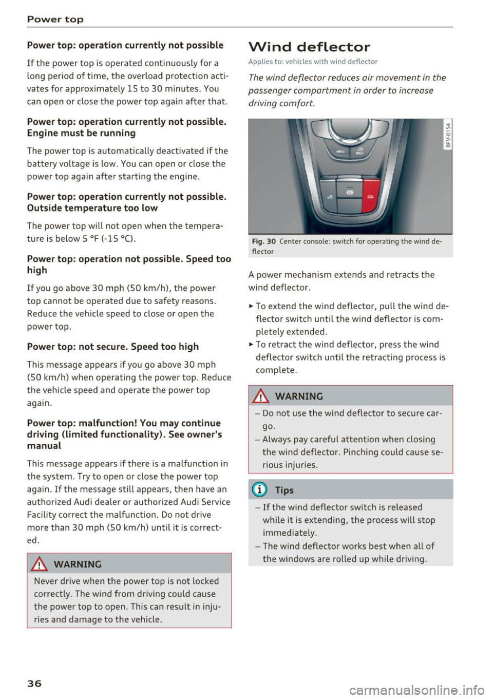
The wind deflector reduces air movement in the
passenger compartment in order to increase driving comfort.
Fi g. 30 Ce nter conso le: switch for ope ra ting t he w ind de
flector
A power mechanism extends and retracts the
wind deflector.
., To extend the wind deflector, pu ll the wind de
flector switch unti l the wind def lector is com
pletely extended .
., To retract the wind deflector, press the wind
deflector switch until the retracting process is
complete .
.&,. WARNING
-Do not use the w ind deflector to secure car
go .
- Always pay careful attention when clos ing
the wind deflector. Pinch ing could ca use se
r ious inju ries .
(j) Tips
-If the w ind deflector sw itch is released
wh ile it is extending, the process will stop
immediately .
- T he wind deflec to r works best when all of
the windows are rolled up while driving .
Page 40 of 314
Power top
• Insert the hex socket wrench into the bolt and
remove it completely ¢
fig. 34. Also remove
the bolt on the front passenger's side.
Step 3: Close the power top
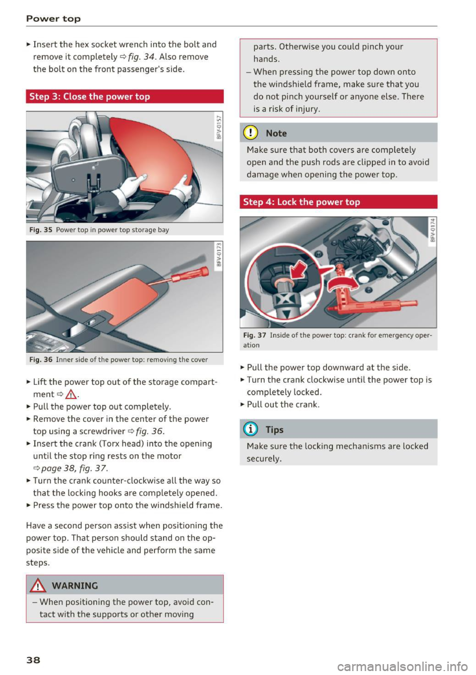
Fig. 35 Power top in power top s torage bay
Fig. 36 Inner side o f th e powe r top: re m ov ing the cover
• Lift the power top out of the storage compart
ment ¢,& .
• Pull the power top out completely.
• Remove the cover in the center of the power
top using a screwdriver ¢
fig. 36.
• Insert the crank (Torx head) into the opening
until the stop ring rests on the motor
¢page 38, fig . 37 .
• Turn the crank counter-clockwise all the way so
that the locking hooks are completely opened.
• Press the power top onto the windshield frame.
Have a second person assist when positioning the
power top. That person should stand on the op
posite side of the vehicle and perform the same
steps.
_& WARNING
- When positioning the power top, avoid con
tact with the supports or other moving
38
parts. Otherwise you could pinch your
hands.
- When pressing the power top down onto
the windshield frame, make sure that you
do not pinch yourself or anyone else . There
is a risk of injury.
(D Note
Make sure that both covers are completely
open and the push rods are clipped in to avoid
damage when opening the power top.
Step 4: Lock the power top
Fig. 37 Inside of the power top: crank for emergency oper
ation
• Pull the power top downward at the side.
• Turn the crank clockwise until the power top is
completely locked .
•Pullout the crank.
(D Tips
Make sure the locking mechanisms are locked
securely.
Page 50 of 314
Seats and storage
Center armrest
Applies to: vehicles with center armrest
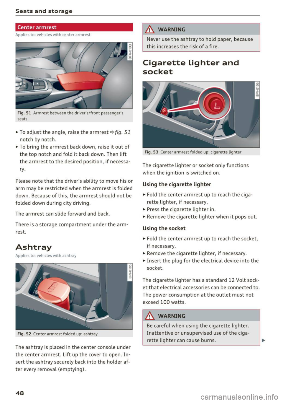
Fig. 51 Armrest between the driver's/front passenger's
seats.
,.. To adjust the angle, raise the armrest q fig. 51
notch by notch .
,.. To bring the armrest back down, raise it out of
the top notch and fold it back down. Then lift
the armrest to the desired pos ition, if necessa
ry .
Please note that the d river 's ability to move his or
arm may be restricted when the armrest is folded
down. Because of this, the armrest should not be
folded down during city driving.
The armrest can slide forward and back.
There is a storage compartment under the arm
rest .
Ashtray
Applies to : vehicles with ashtray
Fig . 52 Cente r armrest folded up: asht ray
The ashtray is p laced in the center console under
the center armrest. Lift up the cover to open . In
sert the asht ray securely back into the hold er af
ter eve ry removal (emptying) .
48
A WARNING
Never use the ashtray to hold paper, because
this increases the risk of a fire .
Cigarette lighter and
socket
Fig. 53 Center armrest folded up: cigarette lighter
The cigarette lighter or socket only functions
when the ignition is switched on.
Using the cigarette lighter
,.. Fold the center armrest up to reach the ciga-
rette lighter, if necessary .
,.. Press the cigarette lighter in.
,.. Remove the cigarette lighter when it pops out.
Using the socket
,.. Fold the center armrest up to reach the socket,
if necessary .
,.. Remove the c igarette lighter, if necessary .
,.. Insert the p lug for the electrical device into the
socket.
The cigarette lighter has a standard 12 Volt sock et that electrica l accessories can be connected to.
The power consumption at the outlet must not
exceed 100 watts.
A WARNING
Be careful when using the cigarette lighter.
Inattentive or unsupervised use of the ciga
rette lighter can cause burns .
-
Page 52 of 314
Sea ts and stor age
Storage compartment between the seat
backrests
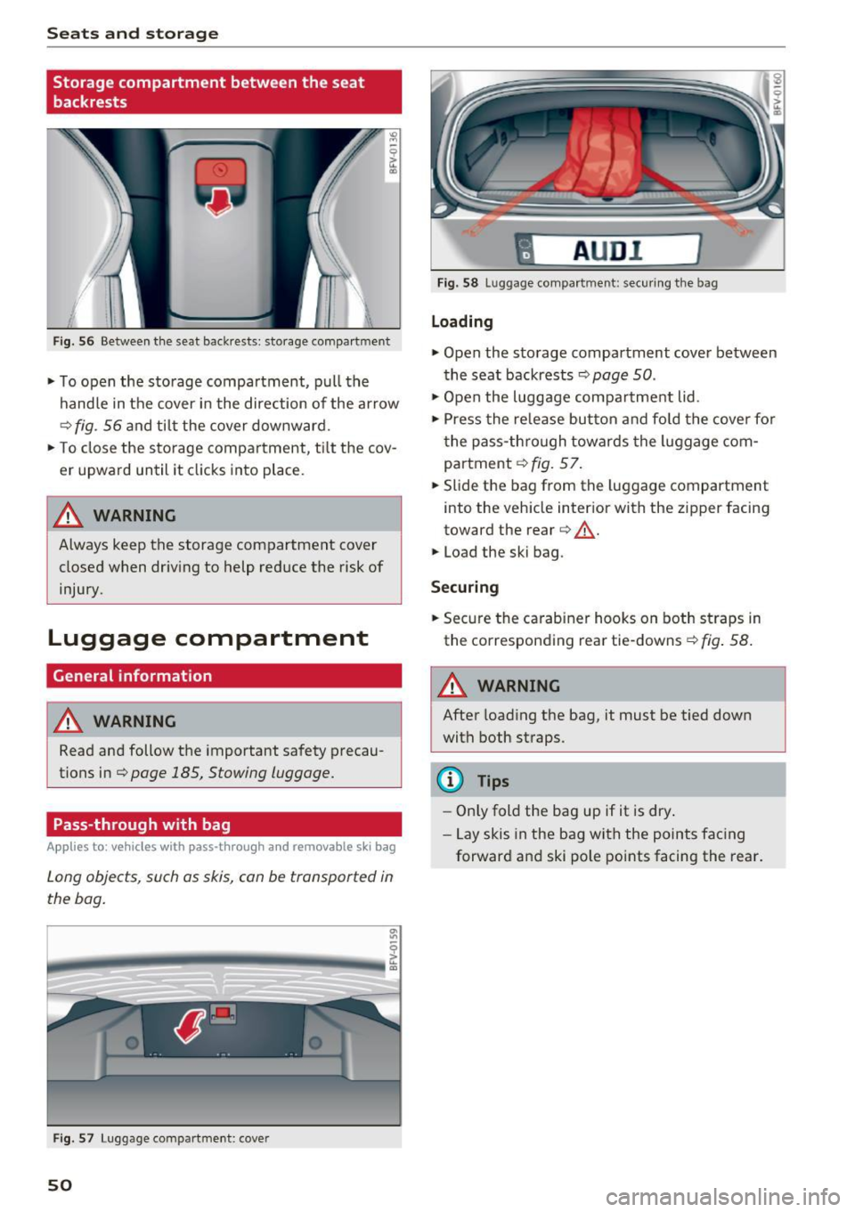
Fig . 56 Between th e seat backrests: storage compartment
• To open the storage compartment, pull the
handle in the cover in the direction of the ar row
r::::> fig . 56 a nd til t the cover downward.
• To close the s torage compa rtment, t ilt the cov
er upward until it clicks into place .
_& WARNING
Always keep the storage compartment cover
closed when dr iv ing to help reduce the risk of
injury.
Luggage compartment
General information
A WARNING
Read and follow the important safety precau
tions in¢
page 185, Stowing luggage.
Pass-through with bag
Applies to: vehicles with pass-through and removable s ki bag
Long objects , such as skis, can be transported in
the bag .
Fig . 57 Luggage compartme nt: cover
50
fl AUD I 1
Fig. 58 Luggage compa rtment: secu ring the bag
Loading
• Open the storage compartment cover between
the seat backrests ¢
page 50.
• Open the luggage compa rtment lid .
• Press the release button and fo ld the cove r fo r
t he pass-th rough towards the luggage com
partment ¢
fig. 57.
• Slide the bag from the luggage compartment
into the vehicle inter ior with the zipper facing
toward the rear
r::::> .&_.
• Load the ski bag.
Securing
• Secure the carabine r hooks on both straps in
the corresponding rea r tie-downs
r::::> fig . 58.
A WARNING
After loading the bag, it must be tied down
with both straps.
(I} Tips
-Only fold the bag up if it is dry.
- Lay skis in the bag with the points facing
forward and ski pole points facing the rear.
-
Page 61 of 314
CD
CD
.... N
" N ...... 0 r--. V, co
Steering
Adjusting the steering wheel position
The steering wheel position is fully adjustable up
and down and forward and back.
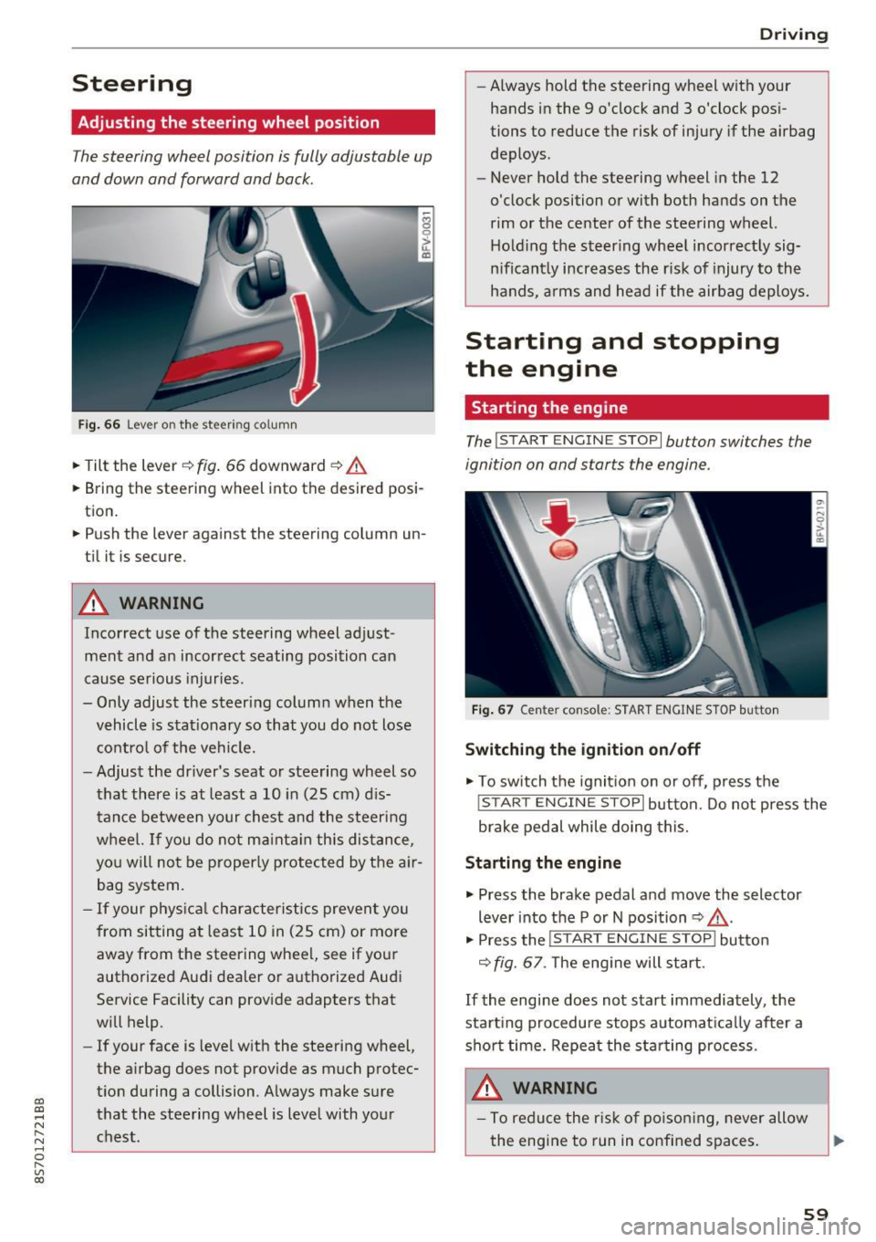
Fig . 6 6 Lever on th e steering column
... Tilt the lever c:::> fig . 66 downward c:::> A
... Bring the steering wheel into the desired posi
tion .
... Push the lever against the steering column un
t il it is secure.
A WARNING
Incorrect use of the steering wheel adj ust
ment and an incorrect seating posi tion can
cause se rious injuries.
- Only adjust the steering column when the vehicle is stat ionary so that you do not lose
cont ro l of the ve hicl e.
- Adjust the dr iver's seat or steering wheel so
that there is at least a 10 in (25 cm) d is
t an ce betwee n your chest a nd the s teering
w heel. If you d o not m aint ain this dis tance,
yo u will no t be proper ly protected by the a ir
bag system.
- If your phys ic al characteris tic s preven t you
from sit ting at least 10 in ( 25 cm) or mo re
away from the steering wheel, see if yo ur
authorized Audi dealer or autho rized Audi
Service Facility can prov ide adapters that
will help.
- If your face is level with the steering wheel,
the a irbag does not provide as much protec
t io n during a collision. A lways make s ure
that the steering wheel is level with you r
chest.
D rivi ng
-Always hold the steering wheel with your
hands in the 9 o'clock and 3 o'clock pos i
tions to reduce the risk of injury if the airbag
deploys.
- Never hold the steering wheel in the 12
o'clock position or with both hands on the
rim or the center of the stee ring wheel.
H old ing the steer ing whee l incorrect ly sig
n ificant ly increases the r isk of injury to the
hands, a rms and head if the airbag deploys.
Starting and stopping
the engine
Starting the engine
The ! S TART ENGINE STOPI button switches the
ignition on and starts the engine .
Fig . 67 Center console: START ENGINE STOP b utto n
Switching the ignition on /off
... To switch t he ignit io n on or off, press t he
!START ENGINE STOPI but ton. Do not press the
brake pedal while doing this.
Starting the engine
... Press the brake pedal a nd move the selector
lever into the P or N position
c:::> ,&. .
... Press the !START ENGINE STOP I butto n
<=:> fig. 67 . The eng ine will start.
If the engine does not start immediately, the
sta rt ing procedure stops automa tica lly after a
sho rt time. Repea t the s ta rt ing process .
A WARNING
-To redu ce the r is k of poiso ning, never allow
the eng ine to run in confined spaces.
59