display AUDI TT ROADSTER 2017 Owners Manual
[x] Cancel search | Manufacturer: AUDI, Model Year: 2017, Model line: TT ROADSTER, Model: AUDI TT ROADSTER 2017Pages: 314, PDF Size: 76.54 MB
Page 5 of 314
co
co
.... N
" N .... 0
" "' c:o
Opening the selection/options menu with
the control knob . . . . . . . . . . . . . . . . . . . . 102
Letter/number speller . . . . . . . . . . . . . . . . 102
Free text search . . . . . . . . . . . . . . . . . . . . . 104
Menus and Symbols . . . . . . . . . . . . . . . . . . 105
Voice recognition system . . . . . . . . 108
Operating . . . . . . . . . . . . . . . . . . . . . . . . . . 107
Command overview information . . . . . . . . 108
Commands . . . . . . . . . . . . . . . . . . . . . . . . . 109
Telephone . . . . . . . . . . . . . . . . . . . . . . . . 114
Introduction . . . . . . . . . . . . . . . . . . . . . . . . 114
Setup . . . . . . . . . . . . . . . . . . . . . . . . . . . . . 114
Using the te lephone . . . . . . . . . . . . . . . . . 116
Favorites . . . . . . . . . . . . . . . . . . . . . . . . . . . 119
Messages . . . . . . . . . . . . . . . . . . . . . . . . . . 119
L istening to voicemail . . . . . . . . . . . . . . . . 121
Emergency call functions . . . . . . . . . . . . . 122
Directory . . . . . . . . . . . . . . . . . . . . . . . . . . . 122
Settings . . . . . . . . . . . . . . . . . . . . . . . . . . . 124
Safety belt microphone . . . . . . . . . . . . . . . 125
Troubleshooting . . . . . . . . . . . . . . . . . . . . . 126
Audi connect . . . . . . . . . . . . . . . . . . . . . 127
Introduction . . . . . . . . . . . . . . . . . . . . . . . . 127
Setup . . . . . . . . . . . . . . . . . . . . . . . . . . . . . 127
Configuration through myAudi . . . . . . . . . 128
Audi connect services. . . . . . . . . . . . . . . . . 129
W i-F i hotspot . . . . . . . . . . . . . . . . . . . . . . . 131
Configur ing the data connect ion . .. .. .. .
About Audi connect ............ ..... .
Troubleshooting .................... .
N .
. av1gat1on .. ................ ..... .
132
133
135
136
Opening navigation . . . . . . . . . . . . . . . . . . 136
Entering a destination . . . . . . . . . . . . . . . . 137
Cancel route guidance . . . . . . . . . . . . . . . . 141
Home address . . . . . . . . . . . . . . . . . . . . . . 142
Favorites . . . . . . . . . . . . . . . . . . . . . . . . . . . 142
Directory contacts . . . . . . . . . . . . . . . . . . . 142
Addit ional settings . . . . . . . . . . . . . . . . . . 142
Map ... .. ... ... .. .. .... ... .. .. .. .. . 144
Online map display . . . . . . . . . . . . . . . . . . 147
Accessing traffic information . . . . . . . . . . 148
Troubleshooting . . . . . . . . . . . . . . . . . . . . . 150
Table of contents
Radio ...... .. .. .................. .
151
Opening the radio . . . . . . . . . . . . . . . . . . . 151
Radio funct ions . . . . . . . . . . . . . . . . . . . . . 152
Radio menu . . . . . . . . . . . . . . . . . . . . . . . . 153
Favorites . . . . . . . . . . . . . . . . . . . . . . . . . . . 153
Additional settings . . . . . . . . . . . . . . . . . . 154
Troubleshooting . . . . . . . . . . . . . . . . . . . . . 155
Med ia .... .. .. .. .... .. .. .... ... .. .. 156
Introduction ... .. .. ...... ....... .. .. 156
Notes . . . . . . . . . . . . . . . . . . . . . . . . . . . . . 156
Media drives . . . . . . . . . . . . . . . . . . . . . . . . 157
Bluetooth audio player . . . . . . . . . . . . . . . 159
Wi-Fi audio player . . . . . . . . . . . . . . . . . . . 160
Online media and Internet radio . . . . . . . . 161
Multimedia connections . . . . . . . . . . . . . . 162
Playing media . . . . . . . . . . . . . . . . . . . . . . . 164
Additional settings . . . . . . . . . . . . . . . . . . 167
Supported media and file formats . . . . . . 169
Troubleshooting .. .. ................. 171
Audi smartphone interface . . . . . . 173
Setup . . . . . . . . . . . . . . . . . . . . . . . . . . . . . 173
Operating . . . . . . . . . . . . . . . . . . . . . . . . . . 173
Troubleshooting .. .. ................. 174
System settings .................. 175
Setting the date and time . . . . . . . . . . . . . 175
MM I settings . . . . . . . . . . . . . . . . . . . . . . . 175
Connection manager . . . . . . . . . . . . . . . . . 176
System update . . . . . . . . . . . . . . . . . . . . . . 178
Sound settings . . . . . . . . . . . . . . . . . . . . . . 179
Vo lume settings . . . . . . . . . . . . . . . . . . . . . 179
Restarting the MMI (Reset) . . . . . . . . . . . . 180
Software license information . . . . . . . . . . 180
Safety . . . . . . . . . . . . . . . . . . . . . . . . . . . . 181
Safe driving . . . . . . . . . . . . . . . . . . . . . . 181
Basics . . . . . . . . . . . . . . . . . . . . . . . . . . . . . 181
Correct passenger seating positions . . . . . 182
Driver and passenger side footwell . . . . . . 184
Pedal area . . . . . . . . . . . . . . . . . . . . . . . . . . 184
Stow ing luggage . . . . . . . . . . . . . . . . . . . . 185
Reporting Safety Defects . . . . . . . . . . . . . . 187
Safety belts . . . . . . . . . . . . . . . . . . . . . . 189
General notes . . . . . . . . . . . . . . . . . . . . . . . 189
Why safety belts? . . . . . . . . . . . . . . . . . . . 190
3
Page 6 of 314
Table of content s
Safety belts . . . . . . . . . . . . . . . . . . . . . . . . 192
Safety belt tensioner . . . . . . . . . . . . . . . . . 194
Airbag system ... . ...... ... .. .. ... 19 6
I mportant info rmation . . . . . . . . . . . . . . . 196
F ront airbags . . . . . . . . . . . . . . . . . . . . . . . 200
Mon itoring the Advanced Airbag System . 207
Knee airbags........................ 212
Side airbags . . . . . . . . . . . . . . . . . . . . . . . . 214
Ch ild safety . . . . . . . . . . . . . . . . . . . . . . 218
Important information . . . . . . . . . . . . . . . 218
Ch ild seats . . . . . . . . . . . . . . . . . . . . . . . . . 223
Secur ing ch ild seats . . . . . . . . . . . . . . . . . . 227
Add it io nal info rmation . . . . . . . . . . . . . . . 230
Maintenanc e and Care . . . . . . . . . . . 23 1
Checking and Filling . . . . . . . . . . . . . 23 1
F ue l... .. .. .. .. ... .......... .... .. . 23 1
Refueling . . . . . . . . . . . . . . . . . . . . . . . . . . 232
E ng ine compartment . . . . . . . . . . . . . . . . . 235
Eng ine oi l .... .. ... .. ..... ... .. .. ... 237
Cooling system . . . . . . . . . . . . . . . . . . . . . . 241
Brake fluid . . . . . . . . . . . . . . . . . . . . . . . . . 242
Battery . . . . . . . . . . . . . . . . . . . . . . . . . . . . 243
W indshield washer system . . . . . . . . . . . . 244
Service interval display . . . . . . . . . . . . . . . 245
Wheels ... .. ... ............ .... .. . 246
Wheels and Tires . . . . . . . . . . . . . . . . . . . . 246
Tire pressure monitoring system 263
Care and cleaning . . . . . . . . . . . . . . . . 266
General information . . . . . . . . . . . . . . . . . 266
Ca r washes . . . . . . . . . . . . . . . . . . . . . . . . . 266
C lea ning and care information . . . . . . . . . 267
P lacing your veh icle o ut of se rvice 27 1
Troubleshooting . . . . . . . . . . . . . . . . . 27 2
Emergency assistance . . . . . . . . . . . 272
T runk es cape l atch . . . . . . . . . . . . . . . . . . . 27 2
G eneral informa tion . . . . . . . . . . . . . . . . . 272
Equipment . . . . . . . . . . . . . . . . . . . . . . . . . 272
Tire mobility k it . . . . . . . . . . . . . . . . . . . . . 273
Replac ing whee ls . . . . . . . . . . . . . . . . . . . . 275
Spare tire . . . . . . . . . . . . . . . . . . . . . . . . . . 279
4
Fuses and bulbs . . . . . . . . . . . . . . . . . . 281
E lectrica l fuses . . . . . . . . . . . . . . . . . . . . . . 281
Bu lbs. . . . . . . . . . . . . . . . . . . . . . . . . . . . . . 283
Emergency situations . . . . . . . . . . . . 2 8 4
Genera l . . . . . . . . . . . . . . . . . . . . . . . . . . . . 284
Start ing by push ing or tow ing . . . . . . . . . . 284
Start ing with jumper cables . . . . . . . . . . . 284
Use o f jumper cables . . . . . . . . . . . . . . . . . 28S
T owing with a tow truck . . . . . . . . . . . . . . 286
Raising the vehicle . . . . . . . . . . . . . . . . . . . 288
Accessories and technical data . . 290
Technical data . . . . . . . . . . . . . . . . . . . . 290
Vehicle spec ificat ions . . . . . . . . . . . . . . . . 290
Weights . . . . . . . . . . . . . . . . . . . . . . . . . . . 290
D imens ions. . . . . . . . . . . . . . . . . . . . . . . . . 291
Capaci ties . . . . . . . . . . . . . . . . . . . . . . . . . . 291
Gasoline engines . . . . . . . . . . . . . . . . . . . . 292
Consumer information and
technical data . . . . . . . . . . . . . . . . . . . .
293
Consumer information . . . . . . . . . . 293
Warranty coverages . . . . . . . . . . . . . . . . . . 293
Operat ing your vehicle outside the U.S.A.
or Canada . . . . . . . . . . . . . . . . . . . . . . . . . . 293
Audi Service Repair Manuals and Lite rat ure . . . . . . . . . . . . . . . . . . . . . . . . . . 293
Maintenance. . . . . . . . . . . . . . . . . . . . . . . . 293
Accessor ies a nd techn ica l changes 295
Index .......... ... ............. ... 297
Page 9 of 314
co
co
.... N
" N .... 0
" "' c:o
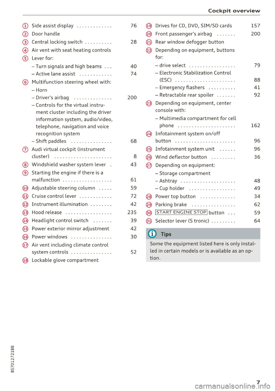
(!) Side assist display ..... ... .. .. .
@ Door handle
®
©
®
Cent ral locking switch
Air vent with seat heating controls
Lever for:
- T urn s ignals and h igh beams .. .
- Active lane assis t ......... .. .
® Multifunction steering wheel with :
- Horn
- Driver's ai rbag .. ......... .. .
- Controls for the virtual instru-
ment cluster includ ing the driver
information system, aud io/video,
telephone, navigation and voice
recogn ition system
- Shift paddles . .... ..... ... . .
0 Aud i v ir tu al co ckpit (instrument
cluster) ... .... .. .... ... .. .. .
@ W indshield washer system lever
® S tarting the engi ne if the re is a
mal func tion .. ........... .. .. .
@ Adjustab le st eering column . ... .
@ Cruise co ntrol lever .. ..... ... . .
@ Ins trument i llum ination ... .. .. .
@ Hood release . .... ......... .. .
0 H eadlight cont rol sw itch .... .. .
@ Power exterior mirror adjustment
@ Power windows . .... ..... ... . .
@ A ir ven t incl uding climate con trol
system controls ... .... ... .. .. .
@ Lockable g love compartment
76
28
40
74
200
68
8
43
6 1
59
72
42
235
39
42
30
52
Coc kpit o ve rv iew
@) Drives for CD, DVD, SI M/SD cards
@ Front passenger's ai rbag ...... .
@ Rear window defogger bu tton
@ Depending on equipment, buttons
for:
- drive select .. .. ............ .
- Electronic Stabilization Control
(ESC) ..... .. .. ............ .
- Emergency flashers . ...... .. .
- Retractab le rear spoiler ...... .
@ Depend ing on equ ipment , center
co nsole with:
- Mu ltimedia compartment for cell
phone .... .. .............. .
~ Infotai nment system on/off
button . .. .. .. .. ............ .
@ Infotainment system unit ... .. .
@ Wind deflector button ........ .
@ Depending o n eq uipment:
- Storage compartment
- Ashtray ... .. ... .. .. ..... .. .
- Cup holder .. ... .. .. ..... .. .
@ Power top button ............ .
@ Parking b rake . .. ............ .
@ I S TAR T ENGINE ST OP I butto n ...
@ Selector lever (S tronic)
@ Tips
1S7
200
79
88
41
92
162
9 6
96
36
48
49
34
62
59
64
Some the equipment listed here is only instal
l ed in certa in models or is available as an op
tion.
7
Page 10 of 314
Instrumen ts and ind icator ligh ts
Instruments and indicator Lights
Instruments
Audi virtual cockpit (instrument cluster)
The instrument cluster is the central information center for the driver.
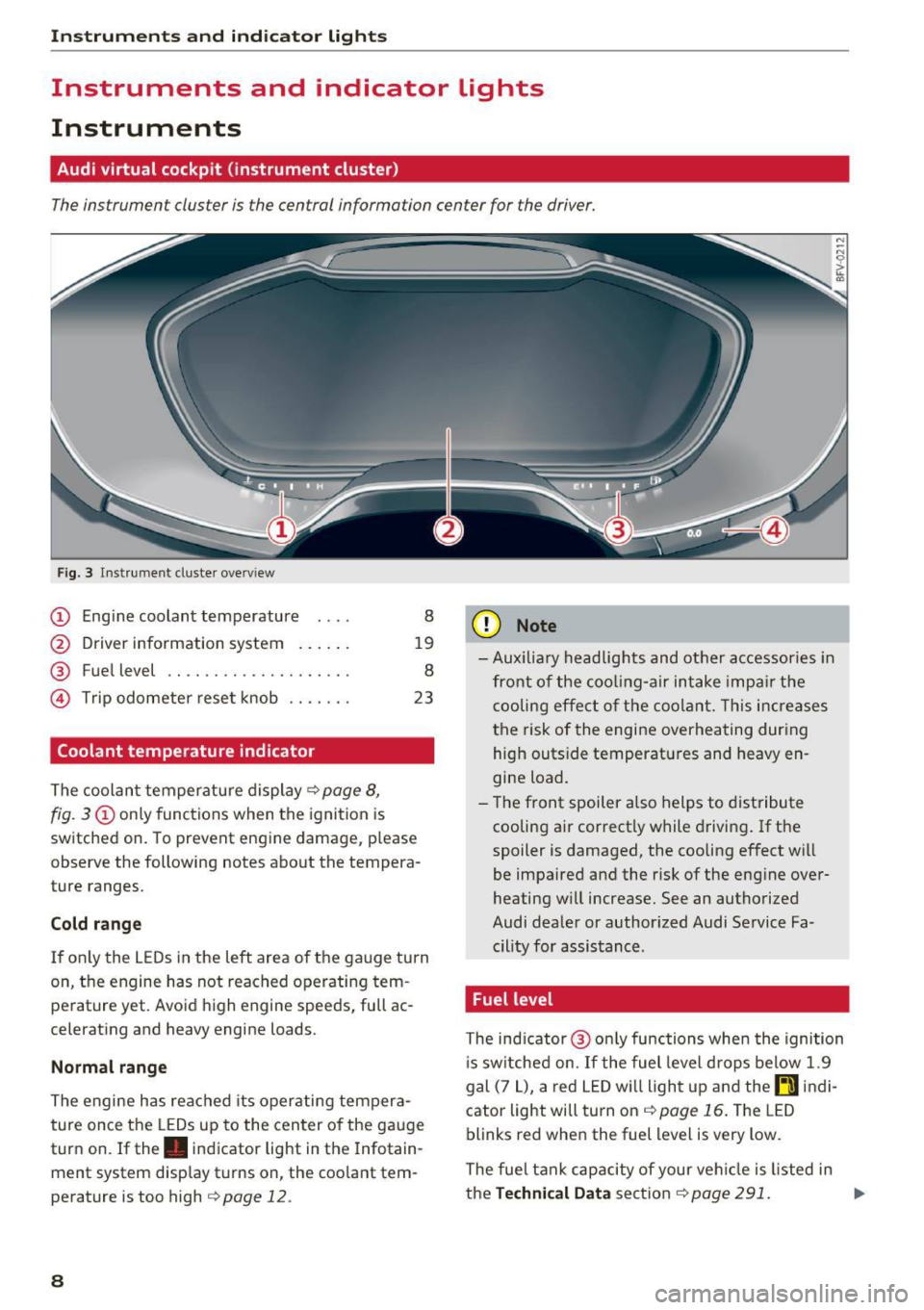
Fig. 3 Instrume nt cluster overv iew
(D Eng ine coolant temperature 8
@ Driver information system . . . . . . 19
® Fuel level . . . . . . . . . . . . . . . . . . . . 8
@ Trip odometer reset knob . . . . . . . 23
Coolant temperature indicator
The coolan t temperature display c:> page 8,
fig. 3
(D only functions when the ignition is
switched on. To prevent engine damage, p lease
observe the following notes about the tempera
ture ranges.
Cold rang e
If o nly the L EDs in the left area of the gauge turn
on, the engine has not reached operating tem
perature yet. Avoid high engine speeds, full ac
celerating and heavy engine loads .
Normal range
The engine has reached its operating tempera
ture once the LEDs up to the center of the gauge
turn on . If the . indicator light in the Infotain
ment system display turns on, the coolant tem
perature is too high
c:> page 12.
8
(D Note
-Aux iliary head lights and other accessories in
front of the coo ling-a ir intake impa ir the
cooling effect o f the coolant. This increases
the risk of the engine overheating during high outside temperatures and heavy en
gine load.
- T he front spoiler a lso helps to distribute
cooling air correctly while driving . If the
spoiler is damaged, the cooling effect will
be impaired and the risk of the eng ine over
heating w ill increase. See an authorized
Audi dealer or author ized Audi Service Fa
cility for assistance .
Fuel level
The indicator @ only func tions when the ignition
i s sw itched on. If the fuel level drops below 1.9
gal (7
L), a red LED wi ll light up and the rD indi
cator light will turn on
c:> page 16 . The LED
blinks red when the fuel level is very low.
The fuel tank capacity of your veh icle is listed in
the
Techni cal Dat a sectio n c:> page 291. ..,_
Page 11 of 314
co
co
.... N
" N .... 0
" "' c:o
(D Note
Never drive until the tank is completely emp
ty. The irregular supply of fuel that results
from that can cause engine misfires . Uncom
busted fuel will then enter the exhaust sys
tem. This can cause overheating and damage
to the catalytic converter .
Indicator lights
Description
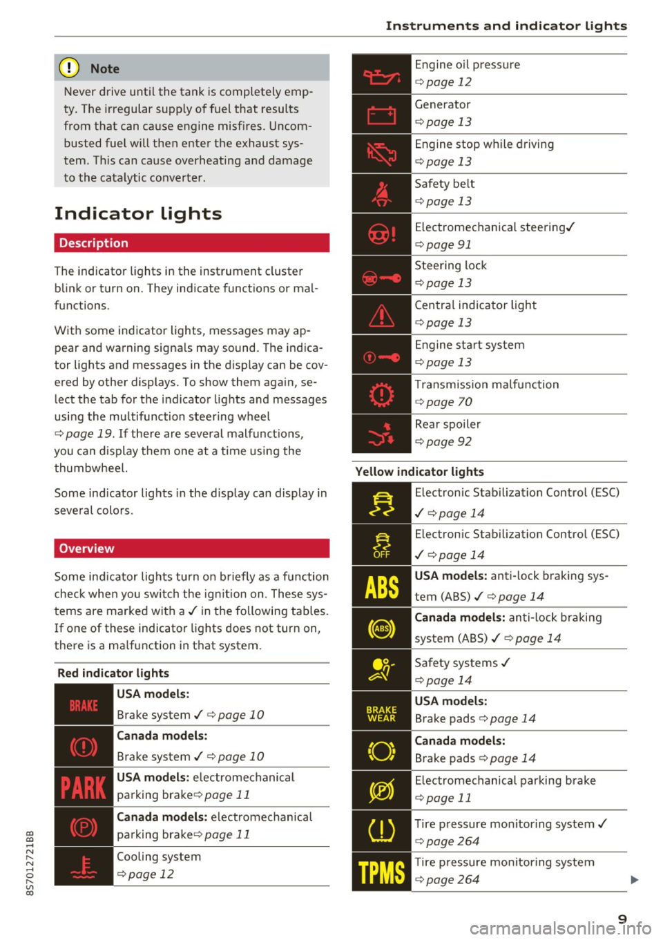
The indicator lights in the instrument cluster
blink or turn on. They indicate functions or mal
functions.
With some indicator lights, messages may appear and warning signals may sound. The indica
tor lights and messages in the display can be cov
ered by other displays. To show them again, se lect the tab for the indicator lights and messages
using the multifunction steering wheel
c;, page 19. If there are several malfunct ions,
you can display them one at a time using the
thumbwheel.
Some ind icator lights in the display can display in
several colors .
Overview
Some indicator lights turn on briefly as a function
check whe n you switch the ign ition on . These sys
tems are marked with a
,I in the following tables.
If one of these indicator lights does not turn on,
there is a ma lfunction in that system.
Red indicator lights
---------------
US A models :
Brake system ./ c;, page 10
Canada models:
Brake system ./ c;, page 10
USA models : electromechanical
parking brake¢
page 11
Canada models: electromechanical
parking brake¢
page 11
Cooling system
<=>page 12
Instruments and indicator lights
Engine oil pressure
c;,page 12
Generator
¢page 13
Engine stop while driving
¢page 13
Safety be lt
c;, page 13
Electromechanical steering./
c;,page 91
Steering lock
¢page 13
Central indicator light
c;,page 13
Engine start system
c;,page 13
Transmission malfunction
c;, page 70
Rear spoiler
c;,page 92
Yellow indicator lights
Electronic Stabilization Contro l (ESC)
,I c;, page 14
Electronic Stabilization Control (ESC)
./ c;, page 14
USA models: anti-lock braking sys
tem (ABS)./
c;, page 14
Canada models: anti-lock braking
system (ABS) ./
c;, page 14
Safety systems ,I
c;,page 14
USA models:
Brake pads c;, page 14
Canada models:
Brake pads c;, page 14
Electromechanical parking brake
c;,page 11
Tire pressure monitoring system../
c>page264
Tire pressure monitoring system
<=>page 264
9
Page 17 of 314
co
co
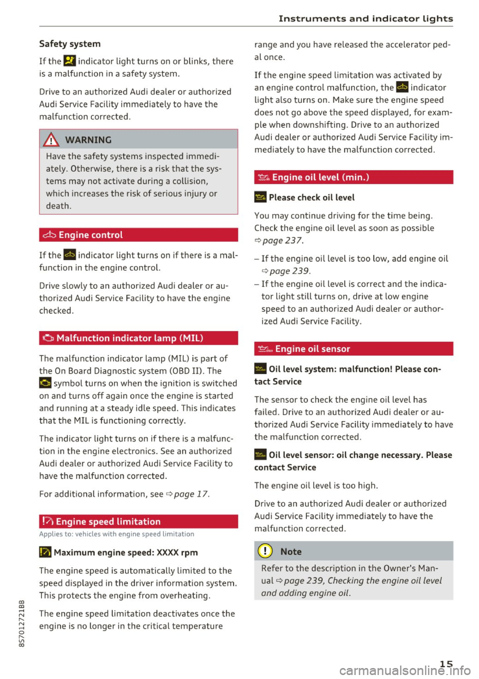
Safety system
If them indicator light turns on or blinks, there
is a malfunction in a safety system.
Drive to an authorized Audi dealer or authorized
Audi Service Facility immediately to have the
malfunction corrected.
_& WARNING
-
Have the safety systems inspected immedi
ately. Otherwise, there is a risk that the sys
tems may not activate during a collision,
which increases the risk of serious injury or death.
c±::, Engine control
If the II indicator light turns on if there is a mal
function in the engine control.
Drive slowly to an authorized Audi dealer or au
thori zed Audi Service Facility to have the engine
checked.
C Malfunction indicator lamp (MIL)
The malfunction indicator lamp (MIL) is part of
the On Board Diagnostic system (OBD II) . The
¢..ij symbol turns on when the ignition is switched
on and turns off again once the engine is started
and running at a steady idle speed. This indicates
that the MIL is functioning correctly.
The indicator light turns on if there is a malfunc
tion in the engine electronics. See an authorized
Audi dealer or authorized Audi Service Facility to
have the malfunction corrected.
For additional information, see¢
page 17.
!?) Engine speed limitation
Appl ies to: vehicles with engine speed li m itation
(ii Maximum engine speed: XXXX rpm
The engine speed is automatically limited to the
speed displayed in the driver information system .
This protects the engine from overheating.
;:::: The engine speed limitation deactivates once the
" ~ engine is no longer in the critical temperature 0
" "' c:o
Instruments and indicator lights
range and you have released the accelerator ped
al once.
If the engine speed limitation was activated by
an engine control malfunction, the
II indicator
light also turns on. Make sure the engine speed
does not go above the speed displayed, for exam
ple when downshifting. Drive to an authorized
Audi dealer or authorized Audi Service Facility im
mediately to have the malfunction corrected.
~ Engine oil level (min.)
Ill Please check oil level
You may continue driving for the time being.
Check the engine oil level as soon as possible
<=> page 237.
-If the engine oil level is too low, add engine oil
¢page 239.
-If the engine oil level is correct and the indica
tor light still turns on, drive at low engine
speed to an authorized Audi dealer or author
ized Audi Service Facility .
"'' Engine oil sensor
• Oil level system: malfunction! Please con
tact Service
The sensor to check the engine oil level has
failed . Drive to an authorized Audi dealer or au
thorized Audi Service Facility immediately to have
the malfunction corrected .
• Oil level sensor: oil change necessary. Please
contact Service
The engine oil level is too high.
Drive to an authorized Audi dealer or authorized
Audi Service Facility immediately to have the
malfunction corrected.
(D Note
Refer to the description in the Owner's Man
ual ¢
page 239, Checking the engine oil level
and adding engine oil.
15
Page 21 of 314
CD
CD
.... N
" N .... 0 r--. V, co
Driver information system
Overview
Fig. S Dr iver information system diagram: classic v iew
Fig. 6 D river information system diagram : expanded view
The driver information system displays various
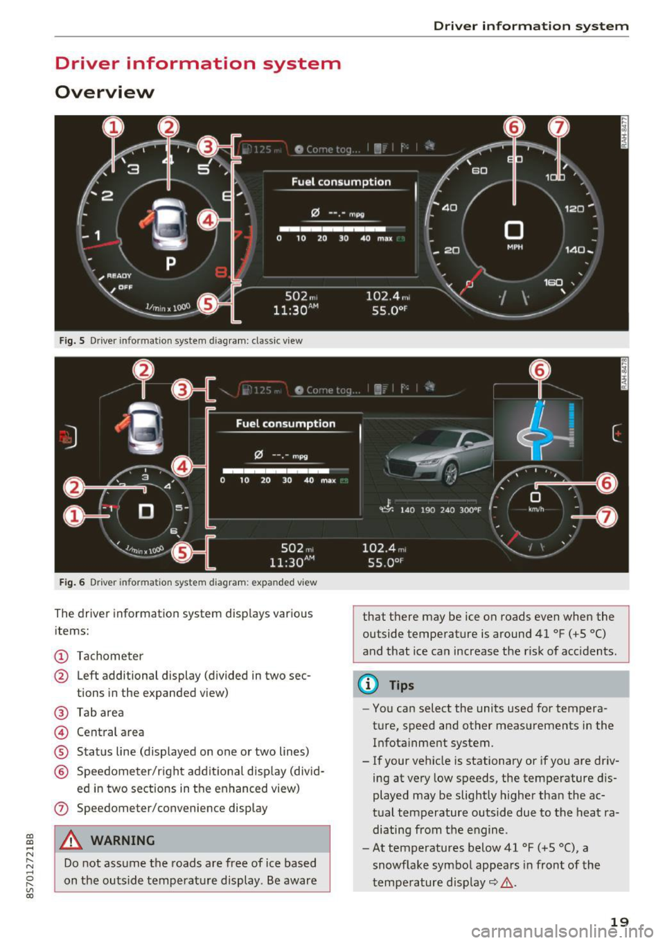
items:
@ Tachometer
@ Left additional display (divided in two sec-
tions in the expanded view)
@ Tab area
@ Central area
® Status line (displayed on one or two lines)
@ Speedometer/right additional display (divid-
ed in two sections in the enhanced view)
(J) Speedometer/convenience display
A WARNING
Do not assume the roads are free of ice based
on the outside temperature display . Be aware
Driver in forma tion system
that there may be ice on roads even when the
outside temperature is around 41 °F ( +S °C)
and that ice can increase the risk of acc idents.
(D Tips
- You can select the units used for tempera
ture, speed and other measurements in the
Infotainment system.
- If your vehicle is stationary or if you are driv
ing at
very low speeds, the temperature dis
played may be slightly higher than the ac
tual temperature outside due to the heat ra
diating from the engine.
- At temperatures below 41 °F (+S °C), a
snowflake symbol appears in front of the
temperature display~ ,&.
19
Page 22 of 314
Driver information system
Multifunction steering
wheel plus
Operating
Apples to: vehicles with multifunctio n steering wheel plus
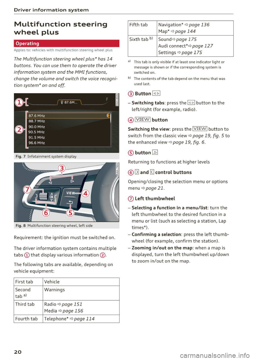
The Multifunction steering wheel plus* hos 14
buttons. You con use them to operate the driver
information system and the MMI functions,
change the volume and switch the voice recogni
tion system* on and off.
F ig. 7 Infotainment system display
Fig. 8 Mult ifunction steering wheel, left side
Requirement: the ign ition must be switched on .
The driver information system contains multiple
tabs
(D that display various informat ion @.
The fo llowing tabs are available, depending on
vehicle equipment :
First tab Veh icle
Second Warnings
tab
a)
T h ird tab Rad
io c:>page 151
Media c:> page 156
Fourth tab Telephone* c:> page 114
20
Fifth tab Navigat ion* c:> page 136
Map * c:> page 144
Sixth tab bl Sound c:> page 175
Audi connect* c:>page 127
Settings c:> page 175
a) This tab is only visible if at least o ne indicator lig ht or
message is shown or if the correspond ing system is
sw itc hed on.
bl Th e contents of the tab depend on the menu that was
u se d last.
® Button I <1 1> I
- Switching tabs: press the I
left/right (for example, radio).
@!VIEWI button
Switching the view: press the !VIEWI button to
switch from the classic view
c:> page 19, fig. 5 to
the enhanced view c:>
page 19, fig. 6.
@ button l2J
Returning to f unctions at higher levels
® l1l and III control buttons
Opening/closing the selection menu o r options
menu
c:>poge 21.
0 Left thumbwheel
-Selecting a function in a menu/list: turn the
left thumbwheel to the desired function in a
menu or list (such as selecting a station, Lap
times*) .
-Confirming a selection: press the left thumb
wheel (for example, confirm the station) .
-Zooming in/out on the map : when a map is
displayed, turn the left thumbwheel up/down
to zoom in/out on the map.
Page 25 of 314
CD
CD
.... N
" N .... 0
" V, co
Tachometer
The tachometer displays the engine speed in rev
olutions per minute (RPM) .
The beginning of the red zone in the tachometer
indicates the maximum permissible engine speed
for all gears once the engine has been broken in
and when it is warm. Before reaching the red
zone, you should shift into the next higher gear,
choose the Dor S selector lever position, or re
move your foot from the accelerator pedal.
@ Note
The needle in the tachometer may only be in
the red area of the gauge for a short per iod of
time or there is a risk of damaging the engine .
The location where the red zone begins varies
depending on the engine.
@) For the sake of the environment
Upshifting early helps you to save fuel and re
duce operating noise.
Odometer
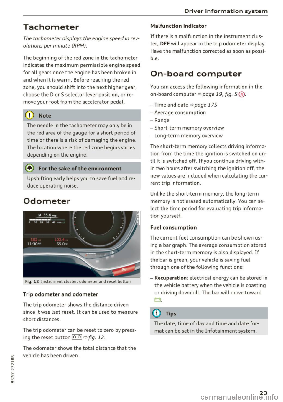
Fig. 12 Instrument cluste r: odomete r and reset button
Trip odometer and odometer
The trip odometer shows the distance driven
since it was last reset . It can be used to measure
short distances .
The trip odometer can be reset to zero by press ing the reset button 10.01
r=> fig. 12.
The odometer shows the total d istance that the
veh icle has been driven.
Driver in forma tion system
Malfunction indicator
If there is a malfunction in the instrument clus
ter,
DEF will appear in the trip odometer disp lay.
Have the malfunction corrected as soon as possi
ble.
On-board computer
You can access the following information in the
on-board computer
r=> page 19, fig . 5 @ .
-Time and date ~page 175
-Average consumption
-Range
- Short-term memory overv iew
- Long-term memory overview
The short -term memory collects driving informa
tion from the time the ignition is switched on un
til it is switched off. If you continue driving with·
in two hours after switching the ignition off, the
new values are included when calculating the cur
rent trip information .
Unlike the short-term memory, the long-term
memory is not erased automatically. You can se
lect the time period for evaluating trip informa
tion yourself .
Fuel consumption
The current fuel consumption can be shown us
ing a bar graph . The average consumption stored
in the short-term memory is also displayed. If
the bar is green, your vehicle is saving fuel
through one of the following functions:
- Recuperation : electrical energy can be stored in
the vehicle battery when the vehicle is coasting or driving downhill. The bar will move toward
CJ .
(D Tips
The date, time of day and time and date for
mat can be set in the Infotainment system.
23
Page 35 of 314
co
co
.... N
" N .... 0
" "' c:o
9. If the garage door or other systems do not
open with the Home link buttons even if the programm ing was successfu l, the system
may use a rolling code instead of a fixed
code. You must also then perform
ro lling
c o de progr amm ing
c:> page 33 .
The other two buttons in the contro l pane l can be
programmed using the instructions given above.
Star t wi th step 3 .
Dele ting button prog ramm ing
The programmed buttons cannot be de leted indi
vidually. They must be deleted all at once . Repro
gram the buttons if necessary.
"' Switch on the ignition.
.. Press both of the outside buttons on the con
trol unit until the yellow LED @turns off and
the green LED@ blinks.
Reprogramming button s
"'Switch on the ignition.
"'T o reprogram an individua l button, press the
desired b utton until the green LED(!) turns off
and the ye llow LED @star ts to blink (after ap
proximately 20 seconds). Release the button
immediately. The programming mode is active
for S m inutes.
"' Cont inue with step 5 .
@ Tips
-The distance needed between the remote
control transm itter and the Homelink mod
ule in the rad iator grille c:>
fig. 27 depends
on the system you are programm ing .
- Depending on the system model, you may need to release the button on the remote
control t ransm itter while it is programming
and press it again. Hold every posit ion you
try when programming for at least 15 sec
onds befo re trying a new posi tion. Keep an
eye on the vehicle turn signals while doing
this .
Op ening and cl osing
Rolling code programming
Applies to: vehicles with garage door opener (Home link)
On some systems, programming a rolling code is
also necessary.
Id enti fying a rolling c ode
"' Press the button in the control unit that is a l
ready programmed again and hold it down.
"' Watch the green LED (!)c:>
page 32 , fig. 26. If
the green L ED bl inks quickly, the system (such
as a garage door) has a roll ing code .
"' Program the rolling code as follows:
Acti vating the sys tem moto r unit
.. Locate the programming button on the system
motor unit. The exact location and color of the
button may vary depending on the system man
ufacturer 's brand .
"' Press the programming button on the system
motor unit (usua lly this will activa te a "display "
on the motor un it) . You now have approx ima te
ly
30 se cond s to prog ram the button in the
control panel.
Programming the button in the control
pan el
.. Press the previous ly programmed button in the
control panel for 2 seconds .
.. To complet e rolling code programming, press
the button again for 2 seconds.
.. On some systems, the button might need to be
pressed a third time to end the programm ing
procedure .
After programming, the system should recogni ze
the signal and operate when the button in the
control panel is pressed . Now you may program
the other buttons as needed .
(D Tips
-The ro lling code can be programmed more
quickly and more easily with the help of a
second person .
- If any d ifficult ies occur when programm ing
the roll ing code, it may be helpful to read
the system operating manual.
33