switch BMW 318i 1997 E36 Owner's Guide
[x] Cancel search | Manufacturer: BMW, Model Year: 1997, Model line: 318i, Model: BMW 318i 1997 E36Pages: 759
Page 144 of 759
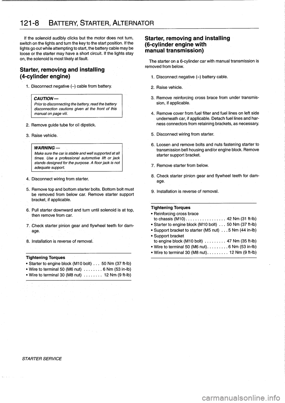
121-
8
BATTERY,
STARTER,
ALTERNATOR
1f
the
solenoid
audibly
cliicks
but
the
motor
does
not
turn,
Starter,
removing
and
installing
switch
on
the
lights
andtum
the
key
to
the
start
position
.
lf
the
(6-cylinder
engine
with
lights
go
out
while
attempting
to
start,
the
battery
cable
may
be
manual
transmission)
loose
or
the
starter
may
have
a
short
circuit
.
If
the
lights
stay
on,the
solenoid
is
most
likely
atfault
.
The
starter
on
a
6-cylinder
car
with
manual
transmission
is
Starter,
removing
and
installing
(4-cylinder
engine)
1
.
Disconnect
negative
(-)
battery
cable
.
1
.
Disconnect
negative
(-)
cable
from
battery
.
CAUTION-
Prior
to
disconnecting
the
battery,
read
the
battery
disconnection
cautions
given
at
the
front
of
this
manual
on
page
viii
.
2
.
Remove
guide
tube
for
oil
dipstick
.
3
.
Raise
vehicle
.
WARNING
-
Make
sure
the
car
ís
stable
and
wefl
supported
at
all
times
.
Use
a
professional
automotive
lift
or
jack
stands
designed
forthe
purpose
.
A
floor
jack
is
not
adequate
support
.
4
.
Disconnect
wiring
from
starter
.
5
.
Remove
top
and
bottom
starter
bolts
.
Bottom
bolt
must
be
removed
from
below
car
.
Remove
starter
support
bracket,
if
applicable
.
removed
from
below
.
2
.
Raise
vehicle
.
3
.
Remove
reinforcing
cross
bracefromunder
transmís-
sion,
if
applicable
.
4
.
Remove
cover
from
fuel
filter
and
fuel
lines
on
left
side
underneath
car,
if
applicable
.
Detach
fuel
lines
and
har-
ness
connectors
from
retainingbrackets,
as
necessary
5
.
Disconnect
wiring
from
starter
.
6
.
Loosen
andremove
bolts
and
nuts
fastening
starter
to
transmission
bell
housing
and/or
engine
block
.
Remove
starter
supportbracket
.
7
.
Remove
starter
from
below
.
8
.
Check
starter
pinion
gear
and
flywheel
teeth
for
dam-
age
.
9
.
Installation
is
reverse
of
removal
.
6
.
Pull
starter
downward
and
turn
until
solenoid
is
at
top,
Tightening
Torques
then
remove
from
car
.
"
Re¡
nforcing
cross
brace
to
chassis
(M10)
..
...............
42
Nm
(31
ft-Ib)
7
.
>Check
starter
pinion
gear
and
flywheel
teeth
for
dam-
"
Starter
to
engine
block
(M10
bolt)
...
50
Nm
(37
ft-Ib)
age
.
"
Support
bracket
to
starter
(M5
nut)
...
5
Nm
(44
in-lb)
"
Support
bracket
8
.
Installation
is
reverse
of
removal
.
to
engine
block
(M10
bolt)
.........
47
Nm
(35
ft-Ib)
"
Wire
to
terminal
50
(M6
nut)
.........
6
Nm
(53
ín-Ib)
"
Wire
to
terminal
30
(M8
nut)
.........
12
Nm
(9
ft-lb)
Tightening
Torques
"
Starter
to
engine
block
(M10
bolt)
...
50
Nm
(37
ft-lb)
Wire
to
terminal
50
(M6
nut)
........
6
Nm
(53
in-lb)
"
Wire
toterminal
30
(M8
nut)
...
,
..:.
12
Nm
(9
ft-Ib)
STARTER
SERVICE
Page 146 of 759
121-1
O
BATTERY,
STARTER,
ALTERNATOR
9
.
Remove
starter
from
above
.
10
.
Check
starter
pinion
gear
and
flywheel
teeth
for
dam-
age
.
11
.
Installation
is
reverse
of
removal
.
Tightening
Torques
"
tntakemanifold
to
cylinder
head
M7
nut
...
.
................
...
.
15
Nm
(11
ft-Ib)
M8
nut/bolt
.............
.
.
..
...
22
Nm
(16
ft-Ib)
"
Starter
to
engine
block
(M10
bolt)
...
50
Nm
(37
ft-Ib)
"
Support
bracket
to
starter
(M5
nut)
...
5
Nm
(44
in-lb)
"
Support
bracket
to
engine
block
(M10
bolt)
.
.
..
..
...
47
Nm
(35
ft-Ib)
"
Wire
toterminal
50
(M6
nut)
.
..
.....
6
Nm
(53
in-lb)
"
Wire
toterminal
30
(M8
nut)
...
.....
12
Nm
(9
ft-Ib)
Solenoid
switch,
removing
and
installing
1
.
Remove
starter
as
described
above
.
Tightening
Torque
2
.
Remove
cover
from
solenoid
switch
.
"
Field
winding
strap
to
starter
(M8)
...
.
12
Nm
(9
ft-Ib)
3
.
Disconnect
fieid
winding
strap
between
starter
motor
and
solenoid
switch
.
NOTE-
The
condition
of
the
field
winding
strap
is
critical
.
If
it
is
damaged,
bumed
or
partially
melted
through,
a
new
or
rebuilt
starter
motor
is
needed
.
4
.
Remove
solenoidswitch
mounting
screws,
and
sepa-
,
rate
solenoid
from
starter
.
See
Fig
.
12
.
CAUTION-
When
installing
fieid
winding
strap
to
starter,
posi-
tion
it
so
that
it
does
not
contact
the
starter
body
.
STARTER
SERVICE
131~184
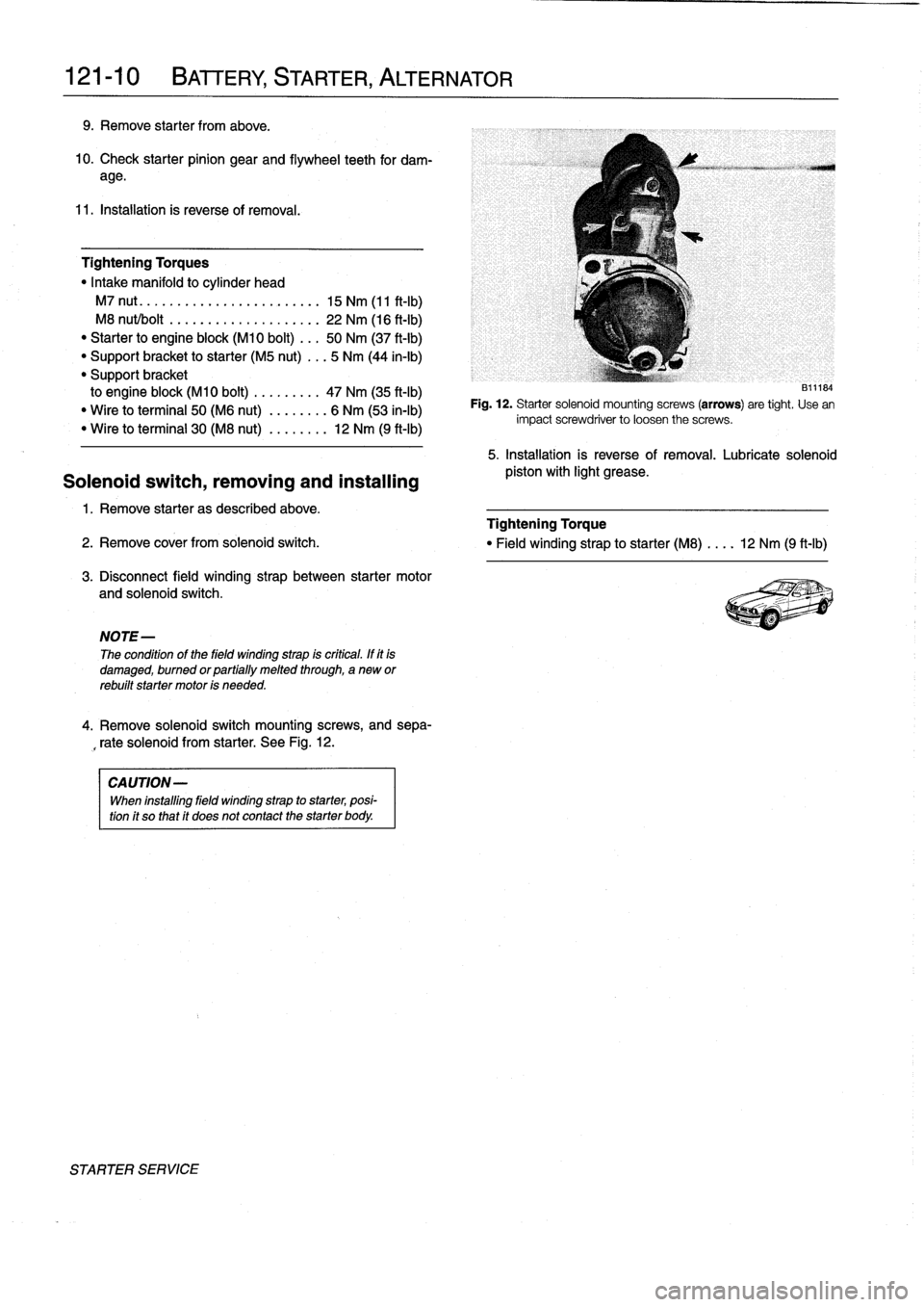
Fig
.
12
.
Starter
solenoid
mounting
screws
(arrows)
are
tight
.
Use
en
impact
screwdriver
to
loosen
the
screws
.
5
.
Installation
is
reverse
of
removal
.
Lubricate
solenoid
pistos
with
light
grease
.
Page 152 of 759
130-
6
FUEL
INJECTION
Warnings
and
Cautions
For
personal
safety,
as
well
as
the
protection
of
sensitive
electronic
components,
the
following
warnings
and
cautions
should
be
adhered
to
when
working
on
the
engine
manage-
ment
system
.
GENERAL
WARNING
-
"
The
ignition
system
produces
high
voltages
that
can
be
fatal
.
Avoid
contact
with
exposed
termi-
nals
.
Use
extreme
caution
when
working
onacar
with
the
ignition
switched
on
or
the
engine
run-
ning
.
"
Do
not
touch
or
disconnect
any
high
voltage
ca-
bles
from
the
coils
or
spark
plugs
while
the
engine
is
running
or
beingcranked
by
the
starter
.
"
Connect
and
disconnect
the
DME
system
wiring
and
test
equipment
leads
only
when
the
ignition
is
switched
off
.
"
Gasoline
is
highly
flammable
and
fts
vaporsare
explosive
.
Do
not
smoke
or
work
on
a
car
near
heaters
or
other
fire
hazards
when
diagnosing
and
repalring
fuel
system
problems
.
Have
a
tire
extinguisher
avaílable
in
case
of
an
emergency
.
"
When
working
onan
open
fuel
system,
wear
suit-
able
hand
protection,
asprolonged
contact
wfth
fuel
can
cause
illnesses
and
skin
disorders
.
"
Renew
fuel
system
hoses,
clamps
and
O-rings
any
timethey
are
removed
.
"
Before
makingany
electrical
tests
that
require
the
engine
to
be
cranked
using
the
starter,
disable
the
ignition
system
as
described
in
120
Ignition
System
.
CAUTION-
"
Prior
to
disconnecting
the
battery,
read
the
bat-
tery
disconnectinn
cautions
given
at
the
front
of
this
manual
onpage
vifi
.
"
Do
not
connect
any
test
equipment
that
delivers
a
12-volt
power
supply
to
terminal
15
(+)
of
the
ig-
nitioncoil
.
The
current
flow
may
damage
the
ECM
.
In
general,
connect
test
equipment
only
as
speclfied
by
BMW,
this
manual,
or
the
equipment
maker
.
"
Only
use
a
digital
multlmeter
for
electrical
test
.
"
Only
use
an
LED
test
light
for
quick
tests
.
"
Disconnecting
the
battery
may
erase
fault
code(s)
stored
in
memory
.
Check
for
fault
codes
prior
to
disconnecting
the
battery
cables
.
ff
the
Check
Engine
light
ís
illuminated,
see100En-
gine-General
for
DME
fault
code
information
.
ff
any
other
system
faults
have
been
detected
(indi-
catedbyan
illuminated
warning
light),
see
an
au-
thorized
BMW
dealer
.
Additional
systems
with
self-diagnostic
capabilities
include,
ABS
(Anti-
lock
brakes),
SRS
(Airbags),
EML
and
ASC+T
and
AST
(Traction
Control)
.
"
Do
not
run
the
engine
wfth
any
of
the
spark
plug
wires
dlsconnected
.
Catalytic
converter
damage
may
result
.
"
Always
waitat
least
40
seconds
afterturning
off
the
ignition
before
removing
the
engine
control
module
(ECM)
connector
.
ff
the
connector
isre-
moved
before
this
time,
residual
power
in
the
sys-
tem
relay
may
damage
the
control
module
.
"
Cleanliness
is
essential
when
working
onan
open
fuel
system
.
Thoroughly
clean
fuel
line
con-
nections
and
surroundlng
areas
before
loosen-
ing
.
Avoid
moving
the
car
.
Only
fnstall
cleanparts
.
"
Fuel
system
cleaners
and
other
chemical
addi-
tives
other
than
those
specifically
recommended
by
BMW
may
damage
the
catalytic
converter,
the
oxygensensor
or
other
fuel
supply
components
.
Page 153 of 759
ELECTRICAL
CHECKS
AND
COMPONENT
TESTING
Main
relay,
testing
The
main
relay
is
energized
via
the
engine
control
module
and
supplies
plus
(+)
power
to
the
many
of
the
engine
man-
agement
components
and
subsystems,
including
the
fuel
pump
relay
.
If
this
relay
is
faulty,
the
engine
will
not
start
.
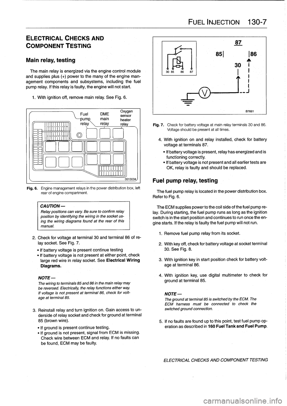
1
.
With
ignition
off,
remove
main
relay
.
See
Fig
.
6
.
.
iommooommmoi
~
"""
Fuel
DME
sensor
CA
UTION-
Relay
positions
can
vary
.
Be
sure
to
confirm
relay
position
by
identífyíng
the
wiring
in
the
socket
us-
ingthe
wiring
diagramsfound
at
the
rearof
this
manual
.
0013034)
Fuel
pump
relay,
testing
FUEL
INJECTION
130-
7
87
851186
30
~j
1
.
Remove
fuel
pump
relay
from
its
socket
.
87661
Fig
.
7
.
Check
for
battery
voltage
at
main
relay
terminals
30
and
86
.
Voltage
should
be
present
at
all
times
.
4
.
With
ignition
on
and
relay
installed,
check
for
battery
voltage
at
terminals
87
.
"
If
battery
voltage
is
present,relay
has
energized
and
is
functioningcorrectly
.
"
lf
battery
voltage
is
not
present
and
al¡
earlier
tests
are
OK,
relay
is
faulty
and
should
be
replaced
.
Fig
.
6
.
Engine
management
relays
in
the
power
distribution
box,
left
rear
of
engine
compartment
.
The
fuel
pump
relay
is
located
in
the
power
distribution
box
.
Refer
to
Fig
.
6
.
The
ECM
supplies
power
to
the
coil
side
of
the
fuel
pump
re-
lay
.
During
starting,
the
fuel
pump
runs
as
long
as
the
ignition
switch
isin
the
start
position
and
continues
to
run
once
theen-
gine
starts
.
If
the
relay
ís
faulty
the
fuel
pump
will
notrun
.
2
.
Check
for
voltage
at
terminal
30
and
terminal
86
of
re-
¡ay
socket
.
See
Fig
.
7
.
2
.
With
key
off,
check
for
batteryvoltage
at
socket
terminal
"
If
battery
voltage
is
present
continue
testing
30
.
See
Fig
.
8
.
"
lf
battery
voltage
is
not
present
at
either
point,
check
large
red
wire
in
relay
socket
.
See
Electrical
Wiring
3
.
With
ignition
key
in
start
position
check
for
battery
volt-
Diagrams
.
age
at
terminal
86
.
NOTE-
4
.
With
ignition
key,
use
digital
multimeter
to
check
for
The
wiring
to
terminals
85
and
86
in
the
main
relay
may
ground
at
terminal
85
.
be
reversed
.
Electrically,
the
relay
functions
either
way
.
lf
voltage
ís
not
present
at
terminal
86,
check
for
volt-
NOTE-
age
at
terminal
85
.
The
ground
atterminal
85
is
switched
by
the
ECM
.
The
ECM
hamess
must
be
connected
to
check
the
3
.
Reinstall
relay
and
turn
ignition
on
.
Gainaccess
to
un-
switched
ground
connection
.
derside
of
relay
socket
and
check
for
ground
at
terminal
85
(brown
wire)
.
5
.
If
no
faults
are
found
up
tothis
point,
testfuel
pump
op-
"
lf
ground
is
present
continue
testing
.
eration
as
described
in
160
Fuel
Tank
and
Fuel
Pump
.
"
If
ground
is
not
present,
signal
from
ECM
is
missing
.
Check
wire
between
ECM
and
relay
.
If
no
faults
can
be
found,
ECM
may
be
faulty
.
ELECTRICAL
CHECKS
AND
COMPONENT
TESTING
Page 155 of 759
Oxygen
Sensor
FUEL
DELIVERY
TESTS
FUEL
INJECTION
130-
9
"
Voltage
at
¡dle
..
.
..
..
....
0
.2
to
0
.8
VDC,
fluctuating
Checking
fuel
delivery
is
afundamental
part
of
trouble-
shooting
and
diagnosing
the
engine
management
system
.
Fuel
pressure
directly
influences
fuel
delivery
.
An
accurate
NOTE-
fuel
pressure
gauge
will
be
needed
to
make
the
tests
.
To
check
sensorresponse
to
lean
and
rich
mixtures,
createenairleak,
orpull
vacuumhoseofffue¡
pressure
There
are
three
significant
fuel
delivery
values
to
be
mea-
regulator
to
increase
fuel
pressure
.
sured
:
3
.
Separate
sensorharness
connector
from
sensor
.
Check
for
battery
voltage
between
terminals
3
and
4
(green
wire
and
brown
wire)
in
main
wiring
harness
side
of
con-
nector
with
engine
running
.
If
voltage
is
not
present,
check
oxygen
sensor
heater
relay
.
See610
Electrical
Component
Locations
.
4
.
Check
heater
element
resistance
between
terminals
3
and
4
in
sensor
side
of
connector
.
If
element
is
electri-
cally
open
(no
continuity),
replace
sensor
.
NOTE-
The
oxygen
sensor
heater
relay
is
mounted
in
the
main
power
distributfon
box
in
the
left
rear
of
the
engine
com-
partment
.
Refer
to
Fig
.
6
.
The
heater
relay
is
energized
wíth
positive
(+)
battery
voltage
from
the
main
relayanda
switched
ground
from
the
ECM
.
See
Electrical
Wir-
ing
Diagrams
.
"
Oxygen
sensor
to
exhaust
pipe
...
..
55
Nm
(41
ft-Ib)
"
System
pressure-created
by
the
fuel
pump
and
main-
tained
by
the
pressure
regulator
.
"
Fuel
delivery
volume-created
by
the
fuel
pump
and
af-
fected
by
restrictions,
suchasclogged
fuel
filter
.
"
Residual
pressure-the
pressure
maintained
in
the
closed
system
after
the
engine
and
fuel
pump
are
shut
off
.
Procedures
for
measuring
the
first
two
quantities
arede-
scribed
in
160
Fuel
Tank
and
Fuel
Pump
.
Residual
fuel
pres-
sure
is
checked
using
the
procedure
detailed
later
in
this
group
.
Operating
fuel
pump
fortests
To
operate
the
fuel
pump
for
testing
purposes
without
hav-
íng
to
runthe
engine,
the
fuel
pump
relay
can
be
bypassed
to
power
the
pump
directly
.
Fuel
pump
relay
location
is
shown
in
Fig
.
6
.
5
.
¡f
oxygen
sensor
doesn't
produce
a
fluctuating
voltage
To
runthe
fuel
pump,
remove
the
fuel
pump
relay
and
con-
and
preheater
circuit
is
OK,
replace
sensor
.
nect
the
socket
for
relayterminal
30
to
the
socket
for
relay
ter-
mina¡
87
with
a
fused
jumper
wire
.
After
completing
the
tests,
NOTE-
remove
the
jumper
wire
.
If
not
already
applied,
coat
the
oxygen
sensor
threads
with
an
anti-seize
compound
before
installation
.
Do
not
CAUTION-
getthe
compound
on
the
sensor
tip
.
"
Relay
locations
may
vary
.
Use
care
when
identi-
fying
relays
and
making
electrical
checks
at
the
fuselrelay
panel
.
See
610
Electrical
Compo
Tightening
Torque
nent
Locations
for
additional
relay
information
.
"
The
fuel
pump
relay
has
a
1
.5
mm2
red
wire
at
ter-
minal
30
in
the
relay
socket
.
Terminal
87
has
a
1
.5
mm
2
greenlviolet
wire
.
See
Electrical
Wiring
Di-
agrams
for
additional
wiring
information
.
NOTE-
Thejumper
wire
should
be
1.5
mm2
(14
ga
.)
and
in-
clude
an
in-line
tuse
holder
with
a15
amp
tuse
.
To
avoid
fuselrelay
panel
damage
from
repeated
connect-
ing
and
disconnecting,
also
include
a
toggle
switch
.
A
heavy-duty
jumper,
BMW
tool
no
.
61
3
050,
is
also
available
from
an
authorized
BMW
dealer
.
FUEL
DELIVERYTESTS
Page 157 of 759
3
.
Observe
fuel
pressure
gauge
after
20
minutes
.
The
pressure
shouldnot
drop
off
more
than
0
.5
bar
from
system
pressure
listed
in
Tablec
.
4
.
When
finished
testing,
disconnect
pressure
gauge
and
reconnect
fuel
line
.
If
the
fuel
system
does
not
maintain
pressure,
check
visual-
¡y
for
leaks
in
fuel
lines
orat
unions
.
Leaks
can
also
be
due
to
a
leaking
injector
or
a
faulty
fuel
pump
check
valve
.
Check
the
pump
check
valve
by
repeating
the
test,
butbefore
turning
the
fuel
pump
off,
pinch
off
theretum
line
at
the
fuel
rail
.
If
the
pressure
is
now
maintained,
the
fault
is
most
likely
the
fuel
pump
check
valva
.
Tabla
c
.
Fuel
Pressure
Specifications
Engine
1
Fuel
pressure
4-cytinder
1
3
.0
t
0
.2
bar
(43
.5
t
2
.9psi)
6-cytinder
M50/S50US
engine
3
.0
t
0
.2
bar
(43
.5
±2
.9psi)
M52/S52US
engine
3
.5
f
0
.2
bar
(51
t
2.9psi)
Fuel
pressure
regulator
response
to
engine
load,
testing
1
.
With
fuel
pressure
gauge
connected,
reinstallfuel
pump
relay
.
Start
engine
and
allow
it
to
idle
.
NOTE-
The
fuel
pressure
should
be
lower
by0
.4-0.7
bar
from
the
specifications
listed
in
Table
c
.
Engine
vacuum
act-
ing
on
the
fuel
pressure
regulator
diaphragm
reduces
the
fuel
pressure
.
2
.
With
engine
idling,
remove
vacuum
hose
from
regula-
tor
.
Pressure
should
increase
.
3
.
Reconnecthose
and
check
that
pressure
decreases
.
4
.
When
finished
testing,
disconnect
pressure
gauge
and
reconnect
fuelline
.
Tighten
hose
clamp
.
0013190
Fig
.
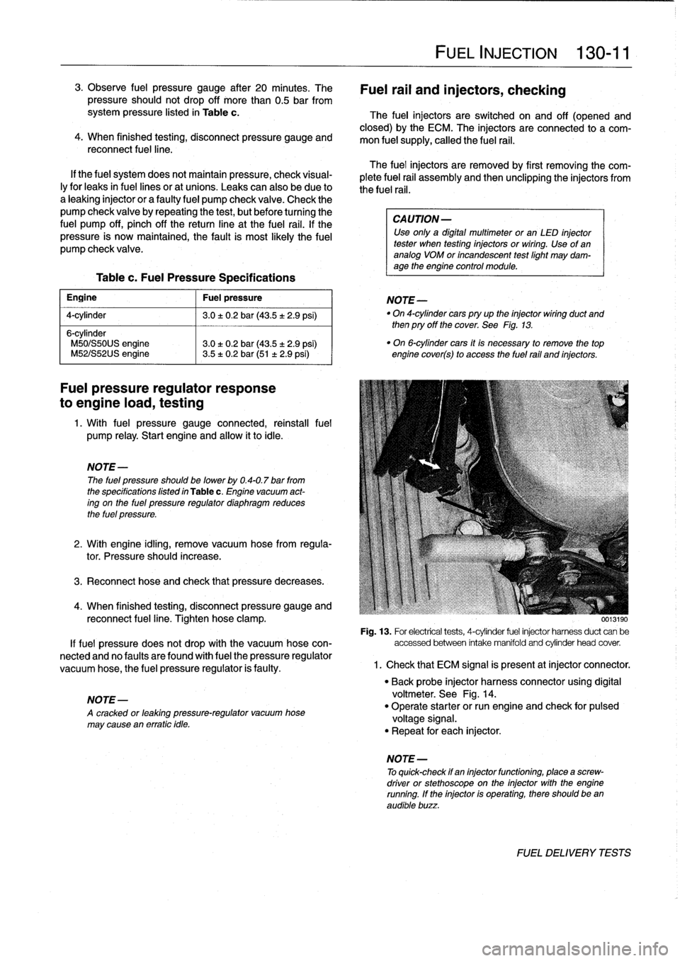
13
.
For
electrical
tests,
4-cytinder
fuel
injector
harnessduct
can
be
If
fuel
pressure
does
not
drop
with
the
vacuum
hose
con-
accessed
between
intake
manifold
and
cytinder
head
cover
.
nected
and
no
faulty
are
found
with
fuel
the
pressure
regulator
vacuum
hose,
the
fuel
pressure
regulator
is
faulty
.
1
.
Check
that
ECM
signal
is
present
atinjector
connector
.
NOTE-
A
cracked
or
leaktng
pressure-regulator
vacuum
hose
may
cause
en
erratic
tdle
.
FUEL
INJECTION
130-
11
Fuel
rail
and
injectors,
checking
The
fuel
injectors
are
switched
on
and
off
(opened
and
closed)
by
the
ECM
.
The
injectors
are
connected
to
a
com-
mon
fuel
supply,
callad
the
fuel
rail
.
The
fuel
injectors
are
removed
by
first
removing
the
com-
plete
fuel
rail
assembly
and
then
unclipping
the
injectors
from
the
fuel
rail
.
CA
UTION-
Use
only
a
digital
multimeter
or
an
LED
injector
tester
when
testing
injectors
or
wiring
.
Use
of
ananalog
VOM
or
incandescent
testlight
may
dam-
age
the
engine
control
module
.
NOTE-
"
On
4-cytindercars
pry
up
the
injector
wiring
duct
and
then
pry
off
the
cover
.
See
Fig
.
13
.
"
On
6-cytinder
cars
it
is
necessary
to
remove
the
top
engine
cover(s)
to
access
the
fuel
rail
and
injectors
.
"
Back
probe
injector
harness
connector
using
digital
voltmeter
.
See
Fig
.
14
.
"
Operate
starter
or
run
engine
and
check
for
pulsad
voltage
signal
.
"
Repeat
for
each
injector
.
NOTE
-
To
quick-check
if
en
injectorfunctioning,
place
a
screw-
driver
or
stethoscope
on
the
injector
with
the
engine
running
.
If
the
injector
is
operating,there
should
been
audible
buzz
.
FUEL
DELIVERYTESTS
Page 163 of 759
BOSCH
DME
MM
AND
M33
.1
COMPONENT
TESTS
AND
REPAIRS
Consult
Table
a
for
engine
application
information
for
the
Bosch
DME
3
.1
and
3
.3.1
systems
.
The
DME
3
.1
and
DME
3
.3
.1
systems
are
similar
in
opera-
tion,
with
knock
control
and
VANOS
operation
being
the
key
differences
.
DME
3
.1
engines
arenot
equipped
with
VANOS
or
knock
detectors,
while
the
DM
E3
.3
.1
system
is
.
CA
UTION-
Use
onty
a
digital
multimeter
when
testing
wiring
.
Use
of
an
analog
VOM
may
damage
the
engine
control
module
.
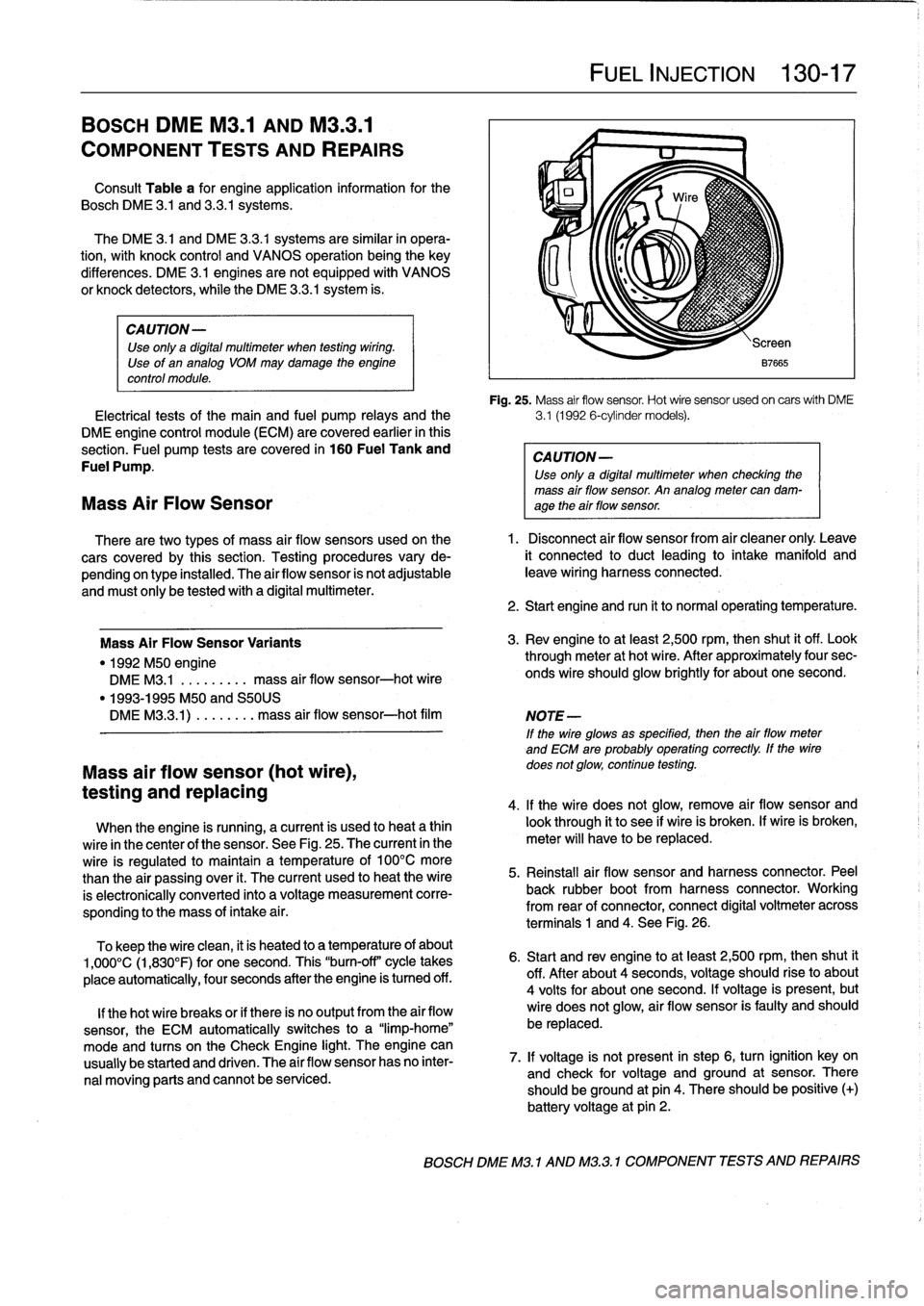
Fig
.
25
.
Mass
air
flow
sensor
.
Hot
wire
sensor
usedon
carswith
DME
Electrical
tests
of
the
main
and
fuel
pump
relays
and
the
3
.1
(1992
6-cylinder
models)
.
DME
engine
control
module
(ECM)
are
covered
earlier
in
this
section
.
Fuel
pump
tests
are
covered
in
160
Fuel
Tank
and
CAUTION-
Fuel
Pump
.
Use
only
a
digital
multimeter
when
checking
the
mass
air
flow
sensor
.
An
analog
meter
can
dam-
Mass
Air
Flow
Sensor
age
theair
flow
sensor
.
There
are
two
types
of
mass
air
flow
sensors
used
onthe
1
.
Disconnect
air
flow
sensor
from
air
cleaner
only
.
Leave
cars
covered
by
this
section
.
Testing
procedures
vary
de-
it
connected
to
duct
leading
to
intake
manifold
and
pending
on
type
installed
.
The
airflow
sensor
is
not
adjustable
leave
wiring
harness
connected
.
and
must
only
be
tested
with
a
digital
multimeter
.
Mass
Air
FlowSensor
Variants
"
1992
M50
engine
DME
M3
.1
.
.
.
.
...
..
mass
air
flow
sensor-hot
wire
"
1993-1995
M50
and
S50US
DMEM33
.1)
.
...
...
.
mass
air
flow
sensor-hot
film
Mass
air
flow
sensor
(hot
wire),
testing
and
replacing
When
the
engine
is
running,
a
current
is
used
to
heat
a
thin
wire
in
the
center
of
the
sensor
.
See
Fig
.
25
.
The
current
in
the
wire
is
regulated
to
maintain
a
temperature
of
100°C
more
than
the
air
passing
over
it
.
The
current
used
to
heat
the
wire
is
electronically
conneced
into
a
voltage
measurement
corre-
sponding
to
the
mass
of
intake
a¡
r
.
To
keep
the
wire
clean,
it
is
heated
to
a
temperature
of
about
1,000°C
(1,830°F)
for
one
second
.
This
"burn-off"
cycle
takes
place
automatically,
four
seconds
after
the
engine
is
tumed
off
.
lf
thehot
wire
breaks
or
if
there
is
no
output
from
the
air
flow
sensor,
the
ECM
automatically
switches
to
a
"limp-home"
mode
and
tucos
on
the
Check
Engine
light
.
The
engine
can
usually
be
started
and
driven
.
The
air
flow
sensor
has
no
inter-
nal
moving
parts
and
cannot
be
serviced
.
FUEL
INJECTION
130-
1
7
2
.
Start
engine
and
run
it
to
normal
operating
temperature
.
3
.
Rev
engine
toat
least
2,500
rpm,then
shut
it
off
.
Look
through
meter
at
hot
wire
.
After
approximately
four
sec-
onds
wire
should
glow
brightly
for
about
one
second
.
NOTE
-
If
the
wire
glowsas
specified,
then
the
airflow
meter
and
ECM
are
probably
operating
correctly
.
lf
the
wire
does
not
glow,
continue
testing
.
4
.
lf
the
wire
does
not
glow,
remove
air
flow
sensor
and
look
through
it
to
see
if
wire
is
broken
.
lf
wire
is
broken,
meter
will
have
to
be
replaced
.
5
.
Reinstall
air
flow
sensor
and
harness
connector
.
Peel
back
rubber
bootfrom
harness
connector
.
Working
from
rear
of
connector,
connect
digital
voltmeter
across
terminals
1
and
4
.
See
Fig
.
26
.
6
.
Start
and
rev
engine
toat
least
2,500
rpm,thenshut
it
off
.
After
about
4
seconds,
voltage
should
riseto
about
4
volts
for
about
one
second
.
lf
voltage
is
present,
but
wire
does
not
glow,
air
flow
sensor
is
faulty
and
should
be
replaced
.
7
.
lf
voltage
is
not
present
in
step
6,
turn
ignition
key
on
and
check
for
voltage
and
ground
at
sensor
.
There
should
beground
at
pin
4
.
There
should
be
positive
(+)
battery
voltage
at
pin
2
.
BOSCH
DME
M3
.1
AND
M32
.1
COMPONENT
TESTS
AND
REPAIRS
Page 164 of 759
130-18
FUEL
INJECTION
The
engine
coolant
temperature
(ECT)
sensor
sends
con-
tinuous
engine
coolant
temperature
information
to
the
ECM
.
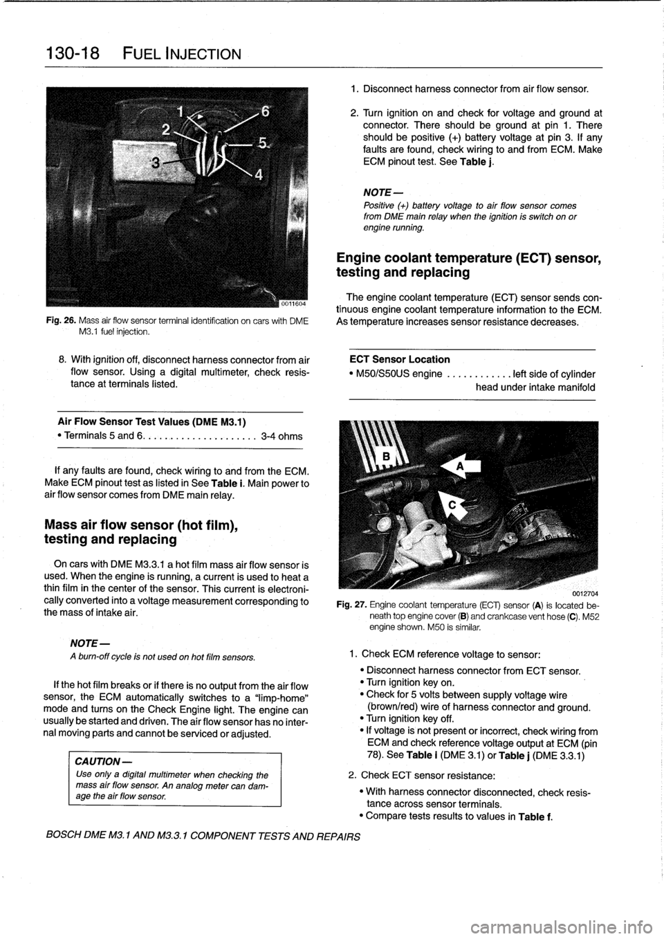
Fig
.
26
.
Mass
air
flow
sensor
terminalidentifcation
on
carswith
DME
As
temperature
increases
sensor
resistance
decreases
.
M3
.1
fuel
injection
.
Mass
air
flow
sensor
(hot
film),
testing
and
replacing
MOTE-
A
burn-off
cycle
is
not
used
on
hot
film
sensors
.
8
.
With
ignition
off,
disconnect
harness
connector
from
air
ECT
Sensor
Location
flow
sensor
.
Using
a
digital
multimeter,
check
resis-
"
M50/S50US
engine
............
left
side
of
cylinder
tance
at
terminals
listed
.
head
under
intake
manifold
Air
Flow
Sensor
Test
Values
(DMEM3
.1)
"
Terminals
5
and
6
.
.
.
.........
..
.
..
....
3-4
ohms
If
any
faults
are
found,
check
wiring
lo
and
from
the
ECM
.
Make
ECM
pinout
test
as
listed
in
See
Table
i
.
Main
power
to
air
flow
sensor
comes
from
DME
main
relay
.
On
cars
with
DME
M3
.3
.1
a
hot
film
mass
air
flow
sensor
is
used
.
When
the
engine
is
running,
a
current
is
used
lo
heat
a
thinfilm
in
the
center
of
the
sensor
.
This
current
is
electroni-
cally
converted
into
a
voltage
measurement
corresponding
to
the
mass
of
intake
air
.
If
thehot
film
breaks
or
if
there
is
no
output
from
the
air
flow
sensor,
the
ECM
automatically
switches
to
a
"limp-home"
mode
and
tucos
on
the
Check
Engine
light
.
The
engine
can
usually
be
started
and
driven
.
The
air
flow
sensor
has
no
inter-
nal
moving
parts
and
cannot
be
senricedor
adjusted
.
CA
UTION-
Use
only
a
digital
multimeter
when
checking
the
mass
air
flow
sensor
.
An
analogmetercan
dam-
age
the
air
flow
sensor
.
BOSCH
DME
M3
.
1
AND
M32
.1
COMPONENT
TESTS
AND
REPAIRS
1
.
Disconnect
harnessconnector
from
air
flow
sensor
.
2
.
Turn
ignition
on
and
check
for
voltage
and
ground
at
connector
.
There
should
beground
at
pin
1
.
There
should
be
positive
(+)
battery
voltage
at
pin
3
.
If
any
faults
are
found,
check
wiring
to
and
from
ECM
.
Make
ECM
pinout
test
.
See
Table
j
.
NOTE-
Positive
(+)
battery
voltage
to
air
flow
sensor
comes
from
DME
main
relay
when
the
ignition
is
switch
on
orengine
running
.
Engine
coolant
temperature
(ECT)
sensor,
testing
and
replacing
0012704
Fig
.
27
.
Engine
coolant
temperature
(ECT)
sensor
(A)
is
located
be-
neath
top
engine
cover
(B)
and
crankcase
vent
hose
(C)
.
M52
engine
shown
.
M50
is
similar
.
1
.
Check
ECM
reference
voltage
to
sensor
:
"
Disconnect
harnessconnector
from
ECT
sensor
.
"
Turn
ignition
keyon
.
"
Check
for
5
volts
between
supply
voltage
wire
(brown/red)
wire
of
harness
connector
and
ground
.
"
Turn
ignition
key
off
.
"
If
voltage
is'
not
present
or
incorrect,
check
wiring
from
ECM
and
check
referencevoltage
output
at
ECM
(pin
78)
.
See
Table
i
(DM
E
3
.1)
or
Table
j
(DME
3
.3
.1)
2
.
Check
ECT
sensor
resistance
:
"
With
harnessconnector
disconnected,
check
resis-
tance
acrosssensor
terminals
.
"
Compare
tests
results
to
values
in
Table
f
.
Page 165 of 759
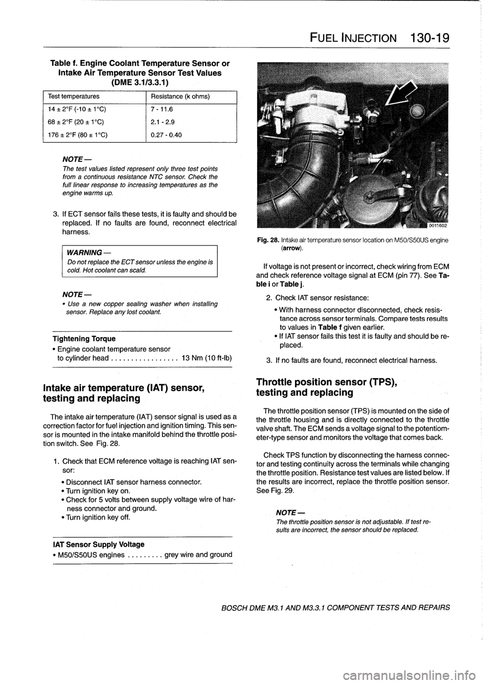
Table
f
.
Engine
Coolant
TemperatureSensor
or
Intake
Air
TemperatureSensor
Test
Values
(DME
3
.113
.3
.1)
Test
temperatures
Resistance
(k
ohms)
14±
2°F
(-10
±
1'C)
7-11
.6
68±
2°F
(20
±
1'C)
2
.1
-2
.9
17612°F
(80
t
V
C)
0
.27-0
.40
NOTE
The
test
values
listed
represent
only
three
test
points
from
a
continuous
resistance
NTC
sensor
.
Check
the
full
linear
response
to
increasing
temperatures
as
the
engine
warms
up
.
3
.
If
ECT
sensor
fails
these
tests,
it
is
faulty
and
should
be
replaced
.
If
no
faults
are
found,
reconnect
electrical
harness
.
WARNING
-
Do
not
replace
the
ECT
sensor
unless
the
engine
is
cold
.
Hot
coolant
can
scald
.
NOTE-
Use
"
a
new
copper
sealing
washer
when
installing
sensor
.
Replace
any
lost
coolant
.
Tightening
Torque
"
Engine
coolant
temperature
sensor
to
cylinder
head
.........
..
.
..
...
13
Nm
(10
ft-lb)
Intake
air
temperature
(IAT)
sensor,
testing
and
replacing
The
intake
air
temperature
(IAT)
sensor
signal
is
usedasa
correction
factor
for
fuel
injection
and
ignition
timing
.
Thissen-
sor
is
mounted
in
the
intake
manifold
behind
the
throttle
posi-
tion
switch
.
See
Fig
.
28
.
Check
TPS
function
by
disconnecting
theharnessconnec-
1
.
Check
that
ECM
reference
voltage
is
reaching
IAT
sen-
tor
and
testing
continuity
across
the
terminalswhile
changing
sor
:
the
throttle
position
.
Resistance
test
values
are
listed
below
.
If
"
Disconnect
IAT
sensor
harness
connector
.
the
resuits
are
incorrect,
replace
the
throttle
position
sensor
.
"
Turn
ignition
keyon
.
See
Fig
.
29
.
"
Check
for
5
volts
between
supply
voltage
wire
of
har-
ness
connector
and
ground
.
NOTE-
"
Turn
ignition
key
off
.
The
throttle
position
sensor
is
not
adjustable
.
If
test
re-
sults
are
incorrect,
the
sensor
should
be
replaced
.
IAT
Sensor
Supply
Voltage
"
M50/S50US
engines
.
........
grey
wire
and
ground
FUEL
INJECTION
130-19
Fig
.
28
.
Intake
air
temperature
sensor
location
on
M50/S50US
engine
(arrow)
.
If
voltage
is
not
present
or
incorrect,
check
wiring
from
ECM
and
check
reference
voltage
signal
at
ECM
(pin
77)
.
See
Ta-
ble
i
or
Table
j
.
2
.
Check
IAT
sensor
resistance
:
"
With
harness
connector
disconnected,
check
resis-
tance
acrosssensor
terminals
.
Compare
tests
resuits
to
values
in
Table
f
given
earlier
.
"
If
IAT
sensor
fafs
thistest
it
is
faulty
and
should
be
re-
placed
.
3
.
If
no
faults
are
found,
reconnect
electrical
harness
.
Throttle
position
sensor
(TPS),
testing
and
replacing
The
throttle
position
sensor
(TPS)
is
mounted
on
the
side
of
the
throttle
housing
and
is
directly
connected
to
the
throttle
valve
shaft
.
The
ECM
sends
a
voltage
signal
to
the
potentiom-
eter-type
sensor
and
monitors
the
voltage
that
comes
back
.
BOSCH
DME
M3
.
1
AND
M32
.1
COMPONENT
TESTS
AND
REPAIRS
Page 166 of 759
130-20
FUEL
INJECTION
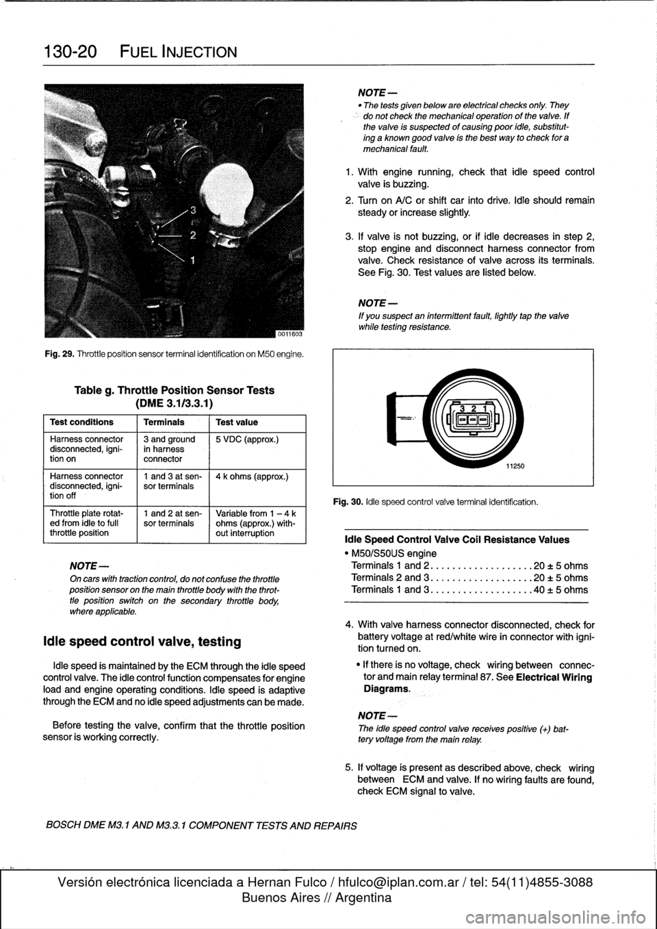
Fig
.
29
.
Throttleposition
sensor
terminal
identification
on
M50
engine
.
Tableg
.
Throttle
Position
Sensor
Tests
(DME3
.113
.3
.1)
Test
conditions
I
Terminals
I
Testvalue
Harness
connector
13
andground
15
VDC
(approx
.)
disconnected,
igni-
in
harness
tion
on
connector
Harness
connector
1
and3
at
sen-
14
k
ohms
(approx
.)
disconnected,
igni-
sor
terminals
tion
off
Throttle
plate
rotat-
1
and
2
at
sen-
Variable
from
1
-
4ked
from
¡dieto
full
sor
terminals
ohms
(approx
.)
with-
throttle
position
out
interruption
¡die
Speed
Control
Valve
Coil
Resistance
Values
"
M50/S50US
engine
NOTE-
Terminals
1
and
2
..
.
................
20
t
5
ohms
On
cars
with
tractioncontrol,
do
not
confuse
the
throttle
Terminals
2
and
3
...................
20
t5
ohms
position
sensor
on
the
main
throttle
body
with
the
throt-
Terminals
1
and
3
..
.
..
:
............
.40
t
5
ohms
tle
positionswitch
on
the
secondary
throttle
body,
where
applicable
.
¡die
speed
control
valve,
testing
¡die
speed
is
maintained
by
the
ECM
through
the
¡die
speed
control
valve
.
The
¡die
controlfunction
compensates
for
engine
load
and
engine
operating
conditions
.
¡die
speed
is
adaptive
through
the
ECM
and
no
¡die
speed
adjustments
can
be
made
.
NOTE-
Before
testing
the
valve,
confirm
that
the
throttle
position
The
idle
speed
controlvalve
receives
positive
(+)
bat-
sensor
is
working
correctly
.
tery
voltage
from
the
main
relay
.
BOSCH
DME
M3
.
1
AND
M3
.3
.1
COMPONENT
TESTS
AND
REPAIRS
NOTE-
"
The
tests
given
below
are
electrical
checks
only
.
They
do
not
check
the
mechanical
operation
of
the
valve
.
If
the
valve
is
suspected
of
causing
poor
idie,
substitut-
ing
a
known
good
valve
is
the
best
way
to
check
for
a
mechanical
fault
.
1
.
With
engine
running,
check
that
¡die
speed
control
valve
is
buzzing
.
2
.
Turn
on
A/C
or
shift
car
finto
drive
.
¡die
should
remain
steady
orincrease
slightly
.
3
.
If
valve
is
not
buzzing,or
if
¡die
decreases
in
step
2,
stop
engine
and
disconnect
harness
connector
from
valve
.
Check
resistance
of
valve
across
its
terminals
.
See
Fig
.
30
.
Test
values
are
listed
below
.
NOTE
-
If
you
suspect
an
intermittent
fault,
lightly
tapthe
valve
while
testing
resistance
.
11250
Fig
.
30
.
¡die
speed
control
valve
terminal
identification
.
4
.
With
valve
harnessconnector
disconnected,
check
for
battery
voltage
at
red/white
wire
in
connector
with
igni-
tion
tumed
on
.
"
If
there
is
no
voltage,
check
wiring
between
connec-
tor
and
main
relayterminal
87
.
See
Electrical
Wiring
Diagrams
.
5
.
If
voltage
is
presentas
described
above,
check
wiring
between
ECM
and
valve
.
If
no
wiring
faults
are
found,
check
ECM
signal
to
valve
.