switch BMW 318i 1997 E36 Manual PDF
[x] Cancel search | Manufacturer: BMW, Model Year: 1997, Model line: 318i, Model: BMW 318i 1997 E36Pages: 759
Page 307 of 759
Ambient
temperaturelclock
MÍM
Aa
.Mi}rm
-Mil"
IMua~naa~u~itacar
"
za
.~
Central
Body
Electronics
0013028
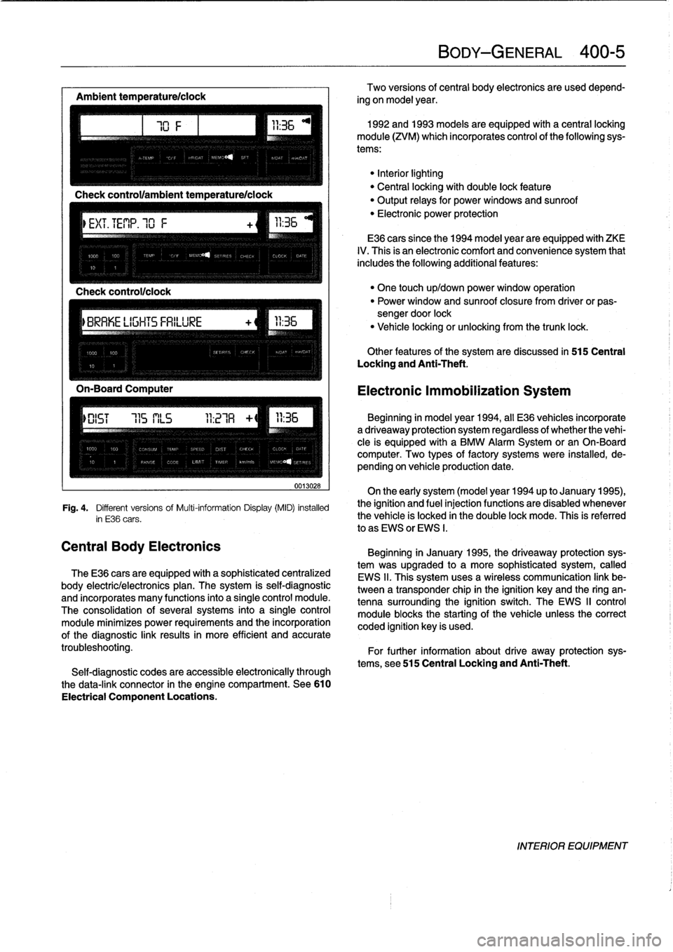
Fig
.
4
.
Different
versionsof
Multi-information
Display(MID)
installed
in
E36
cars
.
The
E36
cars
are
equipped
with
a
sophisticated
centralized
body
electric/electronics
plan
.
The
system
is
self-diagnostic
and
incorporates
many
functions
into
a
single
control
module
.
The
consolidation
of
several
systems
into
a
single
control
module
minimizes
power
requirements
and
the
incorporation
of
the
diagnostic
link
results
in
more
efficient
and
accurate
troubleshooting
.
Self-diagnostic
codes
are
accessible
electronically
through
the
data-link
connector
in
the
engine
compartment
.
See610
Electrical
Component
Locations
.
BODY-GENERAL
400-
5
Two
versions
of
central
body
electronics
are
used
depend-
ing
on
model
year
.
1992
and
1993
models
are
equipped
with
a
central
locking
module
(ZVM)
which
incorporates
control
of
the
following
sys-
tems
:
"Interiorlighting
"
Central
locking
with
double
lock
feature
"
Output
relays
for
powerwindows
and
sunroof
"
Electronic
power
protection
E36
cars
since
the
1994
model
year
are
equipped
with
ZKE
IV
.
This
is
an
electronic
comfort
and
convenience
system
that
includes
the
following
additional
features
:
"
One
touch
up/down
power
window
operation
"
Power
window
and
sunroof
closure
from
driver
or
pas-
sengerdoor
lock
"
Vehicle
locking
or
unlocking
from
the
trunk
lock
.
Other
features
of
the
system
are
discussed
in
515
Central
Locking
and
Anti-Theft
.
Electronic
Immobilization
System
Beginning
in
model
year
1994,
all
E36
vehicles
incorporate
adriveaway
protection
system
regardless
of
whether
the
vehi-
cle
is
equipped
with
a
BMW
Alarm
System
or
an
On-Board
computer
.
Two
types
of
factory
systems
were
installed,
de-
pending
on
vehicle
production
date
.
On
the
early
system
(model
year
1994
up
to
January
1995),
the
ignition
and
fuel
injection
functions
are
disabled
whenever
the
vehicle
is
locked
in
the
double
lock
mode
.
This
is
referred
lo
as
EWS
or
EWS
I
.
Beginning
in
January
1995,
the
driveaway
protection
sys-
tem
was
upgraded
to
a
more
sophisticated
system,
called
EWS
II
.
This
system
uses
a
wireless
communication
link
be-
tween
a
transponder
chip
in
the
ignition
keyand
the
ring
an-
tenna
surrounding
the
ignition
switch
.
The
EWS
II
control
module
blocksthe
starting
of
the
vehicle
unlessthe
correct
coded
ignition
key
is
used
.
For
further
information
about
drive
away
protection
sys-
tems,
see
515
Central
Locking
and
Anti-Theft
.
INTERIOR
EQUIPMENT
Page 311 of 759
ENGINE
HOOD
Hood,
raising
to
service
position
CA
UTION-
Do
not
switch
on
the
windshield
wipers
wlth
the
engine
hood
raised
.
As
a
precaution,
remove
the
wiper
motor
fuse
.
See
610
Electrical
Compo-
nent
Locations
.
1
.
4-door
models
:
Open
hood
fully
.
Remove
bolt
from
hood
hinge
behind
hood
supports
(left
and
right)
.
Raise
hood
to
service
position
.
See
Fig
.
5
.
2
.
2-door
models
:
Open
hood
fully
.
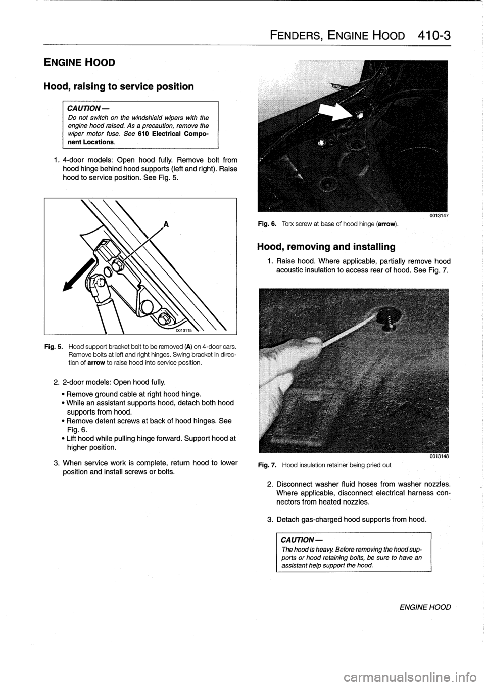
Fig
.
5
.
Hood
support
bracket
boltto
be
removed
(A)
on
4-door
cars
.
Remove
bolts
at
left
and
right
hinges
.
Swing
bracket
in
direc-
tion
of
arrow
to
raise
hood
into
service
position
.
"
Remove
ground
cable
atright
hood
hinge
.
"
Whilean
assistant
supports
hood,
detach
both
hood
supportsfrom
hood
.
"
Remove
detent
screws
at
back
of
hood
hinges
.
See
Fig
.
6
.
"
Lift
hood
while
pulling
hinge
forward
.
Support
hood
at
higher
position
.
3
.
When
service
work
is
complete,
return
hood
to
lower
position
and
instaf
screws
or
bolts
.
FENDERS,
ENGINE
HOOD
410-
3
Fig
.
6
.
Torx
screw
at
base
of
hood
hinge
(arrow)
.
Hood,
removing
and
installing
0013147
1
.
Raise
hood
.
Where
applicable,
partially
remove
hood
acoustic
insulation
to
access
rear
of
hood
.
See
Fig
.
7
.
Fig
.
7
.
Hood
insulation
retainer
being
pried
out
3
.
Detachgas-charged
hood
supportsfrom
hood
.
CAUTION
-
The
hood
is
heavy
.
Before
removing
the
hood
sup-
ports
or
hood
retainingbolts,
be
sure
to
have
an
assistant
help
support
the
hood
.
0013148
2
.
Disconnect
washer
fluid
hoses
from
washer
nozzles
.
Where
applicable,
disconnect
electrical
harness
con-
nectors
fromheated
nozzles
.
ENGINE
HOOD
Page 317 of 759
Door
Hinge
Adjustment
If
the
installed
door
is
uneven
or
out
of
parallel,
shims
can
be
used
to
correct
its
position
.
The
shims
are
placedbehind
the
hinge
plate
and
are
available
in
two
different
thicknesses
(0
.5
mm
and
1
.0
mm)
.
See
Fig
.
4
.
Tightening
Torque
"
Door
hinge
to
door
.............
..
21
Nm
(15
.5
ft-I
b)
"
Door
striker
to
door
...........
...
25
Nm
(18
ft-Ib)
DOOR
PANELS
0
l
o
0013102
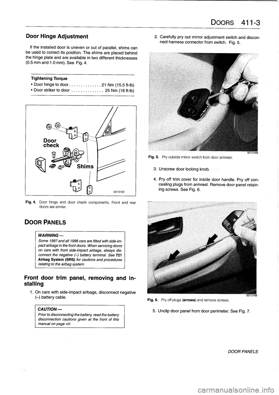
Fig
.
4
.
Door
hinge
and
door
check
components
.
Front
and
rear
doors
are
similar
.
WARNING
-
Some
1997
and
all
1998
cars
are
fitted
with
side-im-
pact
airbags
in
the
front
doors
.
When
servicing
doors
on
cars
with
front
side-impact
airbags,
always
dis-
connect
the
negative
()
battery
terminal
.
See
721
Airbag
System
(SRS)
for
cautions
and
procedures
relating
to
the
airbag
system
.
Front
door
trimpanel,
removing
and
in-
stalling
1
.
On
cars
with
side-impact
airbags,
disconnect
negative
(-)
battery
cable
.
CAUTION
-
Prior
to
disconnecting
the
battery,
read
the
battery
disconnection
cautions
given
at
the
front
of
this
manual
on
page
viii
.
Fig
.
5
.
Pry
outside
mirror
switch
from
door
armrest
.
3
.
Unscrew
door
locking
knob
.
Fig
.
6
.
Pry
off
plugs
(arrows)
and
remove
screws
.
DOORS
411-
3
2
.
Carefully
pry
out
mirror
adjustment
switch
and
discon-
nect
harness
connector
from
switch
.
Fig
.
5
.
5
.
Unclip
door
panel
from
door
perimeter
.
See
Fig
.
7
.
0013168
4
.
Pry
off
trim
cover
for
insíde
door
handle
.
Pry
off
con-
cealing
plugs
from
armrest
.
Remove
door
panel
retain-
ing
screws
.
See
Fig
.
6
.
UU13169
DOOR
PANELS
Page 318 of 759
411-
4
DOORS
6
.
Disconnect
radio
speaker
harness
connector
.
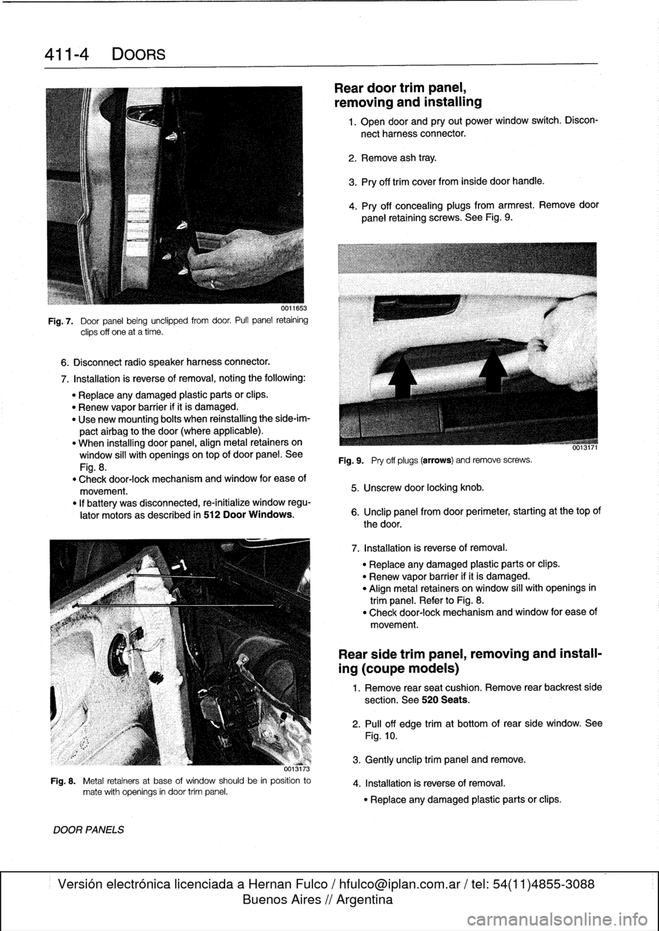
Fig
.
7
.
Door
panel
being
unclipped
from
door
.
Pull
panel
retaining
clips
off
one
at
a
time
.
7
.
Installation
is
reverse
of
removal,
noting
the
following
:
"
Replace
any
damaged
plastic
parts
orclips
.
"
Renew
vapor
barrier
ifit
is
damaged
.
"
Use
new
mounting
bolts
when
reinstalling
the
side-im-
pactairbag
to
the
door
(where
applicable)
.
"
When
installing
door
panel,
align
metal
retainers
on
window
sill
with
openingsontop
of
door
panel
.
See
Fig
.
8
.
"
Check
door-lock
mechanism
and
window
for
ease
of
movement
.
"
If
battery
was
disconnected,
re-initialize
window
regu-
lator
motors
as
described
in
512
Door
Windows
.
373
Fig
.
8
.
Metal
retainers
at
base
of
window
should
be
in
position
to
mate
with
openings
in
door
trim
panel
.
DOOR
PANELS
Reardoor
trimpanel,
removing
and
installing
1
.
Open
door
and
pry
out
power
window
switch
.
Discon-
nect
harness
connector
.
2
.
Remove
ash
tray
.
3
.
Pry
off
trim
cover
from
inside
door
handle
.
4
.
Pry
off
concealing
plugs
from
armrest
.
Remove
door
panel
retaining
screws
.
See
Fig
.
9
.
Fig
.
9
.
Pry
off
plugs
(arrows)
andremove
screws
.
5
.
Unscrew
door
locking
knob
.
6
.
Unclip
panel
from
door
perimeter,
starting
at
thetop
of
the
door
.
7
.
Installation
is
reverse
of
removal
.
"
Replace
any
damaged
plastic
parts
or
clips
.
"
Renew
vapor
barrier
ifit
is
damaged
.
"
Align
metal
retainers
on
window
sill
with
openings
in
trim
panel
.
Refer
to
Fig
.
8
.
"
Check
door-lock
mechanism
and
window
for
ease
of
movement
.
Rear
side
trim
panel,
removing
and
install-
ing
(coupe
models)
1
.
Remove
rear
seat
cushion
.
Remove
rear
backrest
side
section
.
See
520
Seats
.
2
.
Pull
off
edge
trimat
bottom
of
rear
side
window
.
See
Fig
.
10
.
3
.
Gently
unclip
trim
panel
andremove
.
4
.
Installation
is
reverse
of
removal
.
"
Replace
any
damaged
plastic
parts
or
clips
.
Page 319 of 759
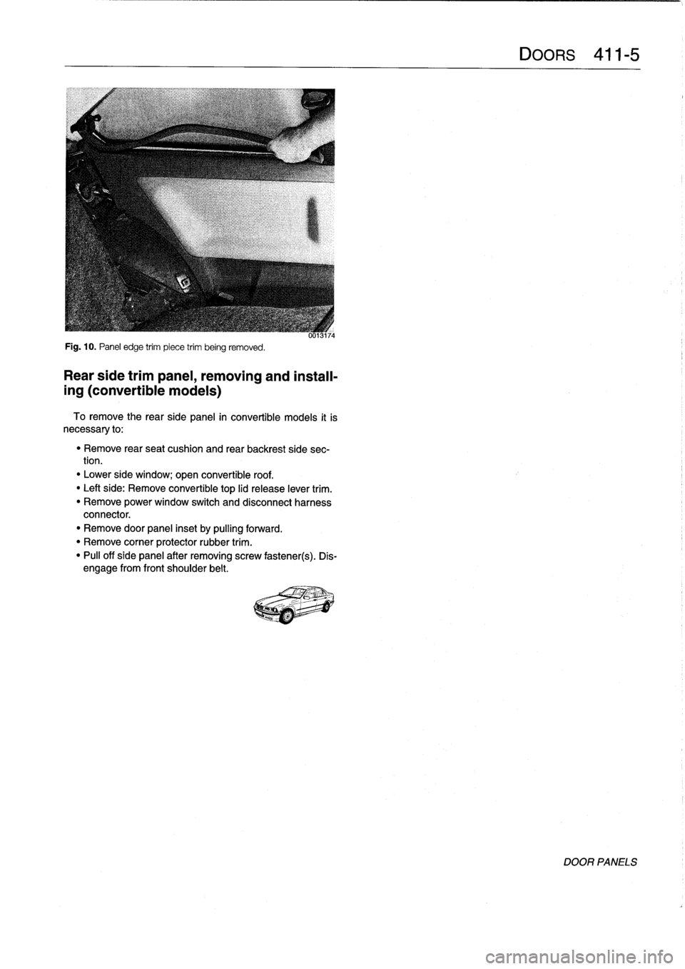
Fig
.
10
.
Panel
edge
trim
piece
trim
being
removed
.
Rear
side
trimpanel,
removing
and
install-
ing
(convertible
models)
To
remove
the
rearside
panel
in
convertible
models
it
is
necessary
to
:
"
Remove
rear
seat
cushion
and
rear
backrest
side
sec-
tion
.
"
Lower
side
window
;
open
convertible
roof
.
"
Leftside
:
Remove
convertible
top
lid
release
lever
trim
.
"
Remove
power
window
switch
and
disconnect
harness
connector
.
"
Remove
door
panel
inset
by
pulling
forward
.
"
Remove
corner
protector
rubber
trim
.
"
Pull
off
side
panel
after
removing
screw
fastener(s)
.
Dis-
engage
from
front
shoulder
belt
.
Page 326 of 759
510-4
EXTERIOR
TRIM,
BUMPERS
Fig
.
8
.
Bumper
cover
retaining
screws
(arrows)
in
left
wheel
weil
.
7
.
Disconnect
harnessconnectors
at
outside
temperature
0013052
sensor
at
rear
of
left
side
of
bumperand
temperatura
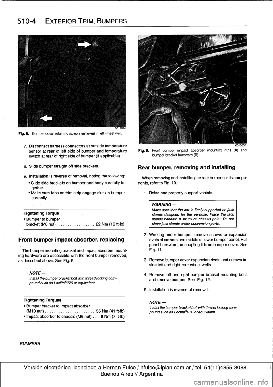
Fig
.
9
.
Front
bumper
impact
absorber
mounting
nuts
(A)
and
switch
at
rear
of
right
side
of
bumper
(if
applicable)
.
bumper
bracket
hardware
(B)
.
8
.
Slide
bumper
straight
off
sida
brackets
.
9
.
Installation
is
reverse
of
removal,
notingthe
following
:
When
removing
and
installing
therear
bumper
or
its
compo-
"
Slide
side
brackets
on
bumper
and
body
carefully
to-
nents,
referto
Fig
.
10
.
gether
.
"
Make
sure
tabs
on
trim
strip
engage
slots
in
bumper
1
.
Raise
and
properly
support
vehicle
.
correctly
.
Tightening
Torque
"
Bumper
to
bumper
bracket
(M8
nut)
............
...
.
.
22
Nm
(16
ft-Ib)
2
.
Working
under
bumper,
remove
screws
or
expansion
Front
bumper
impact
absorber,replacing
rivetsat
corners
and
middle
of
lower
bumper
panel
.
Pull
panel
backward,
uncoupling
it
from
bumper
cover
.
See
Thebumper
mounting
bracket
and
impact
absorber
mount-
Fig
.
11
.
ing
hardware
are
accessible
with
the
Font
bumper
removed,
as
described
above
.
See
Fig
.
9
.
3
.
Remove
bumper
cover
expansion
rivets
and
screws
in-
side
left
and
right
rear
wheel
wells
.
NOTE
-
Install
the
bumper
bracket
boltwith
thread
locking
com-
pound
suchas
Loctite
8
270
or
equivalent
.
Tightening
Torques
"
Bumper
bracket
to
impact
absorber
(M10
nut)
.
..
.
...
.............:.
55
Nm
(41
ft-Ib)
"
Impact
absorber
to
chassis
(M6
nut)
...
9
Nm
(7
ft-Ib)
BUMPERS
Rear
bumper,
removing
and
installing
WARNING
-
Make
sure
that
the
car
is
firmly
supported
on
jack
stands
designad
for
the
purpose
.
Place
the
jack
stands
beneath
a
structural
chassis
point
.
Do
not
place
jack
stands
under
suspension
parts
.
4
.
Remove
left
and
right
bumper
bracket
mounting
bolts
and
remove
bumper
.
See
Fig
.
12
.
5
.
Installation
is
reverse
of
removal
.
NOTE-
Install
the
bumper
bracket
bolt
with
thread
locking
com-
pound
suchas
Loctite®270
or
equivalent
.
Page 338 of 759
512-
8
DOOR
WINDOWS
NOTE-
To
achieve
an
accurate
window
adjustment
in
2-door
models
with
"close
with
door
shut"
feature,
simulate
a
closed
dooras
follows
:
On
early
cars,
manually
turn
the
latch
on
the
door
to
the
closed
position
.
See
Fig
.
16
.
On
latercars,
insert
a
wedge
of
wood
into
the
striker
on
the
body
to
close
the
striker
switch
.
Be
sure
to
open
thero-
tary
latch
(by
pulling
upon
the
door
handle)
or
remove
the
wedge
before
closing
the
door
.
0013066
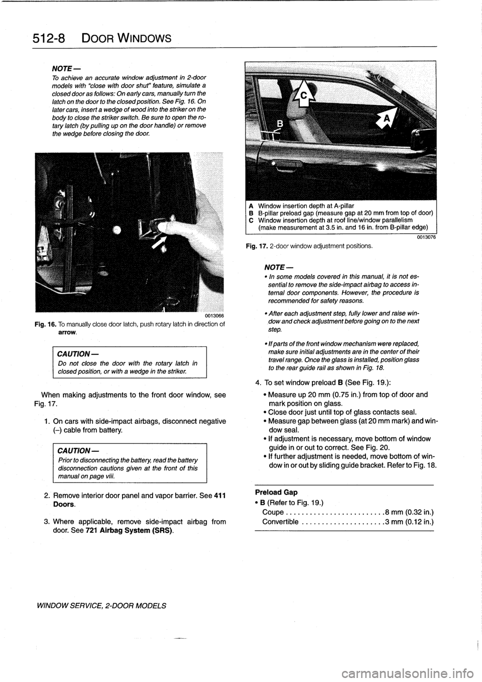
Fig
.
16
.
To
manually
close
door
latch,
push
rotary
latch
in
direction
of
arrow
.
CAUTION-
Do
not
close
the
door
with
therotary
latch
in
closed
position,
orwith
a
wedge
in
the
striker
.
WINDOW
SERVICE,
2-DOOR
MODELS
A
Window
insertion
depth
at
A-pillar
B
B-pillar
preload
gap
(measure
gap
at
20
mm
from
top
of
door)
C
Window
insertion
depth
at
roof
line/window
parallelism
(make
measurement
at
3
.5
in
.
and
16
in
.
from
B-pillar
edge)
Fig
.
17
.
2-door
window
adjustment
positions
.
NOTE-
In"
some
models
covered
inthis
manual,
it
is
not
es-
sential
to
remove
the
side-impact
airbag
to
access
in-
terna¡
door
components
.
However,
the
procedure
is
recommended
for
safety
reasons
.
"
After
each
adjustment
step,
fully
lower
and
raise
win-
dow
and
check
adjustment
before
goingon
to
the
next
step
.
"
1f
parts
of
the
front
window
mechanism
were
replaced,
make
sure
initial
adjustments
are
in
the
center
of
their
travel
range
.
Once
the
glass
isinstalled,
position
glass
to
the
rear
guide
rail
as
shown
in
Fig
.
18
.
4
.
To
set
window
preload
B
(See
Fig
.
1
g
.):
0013076
When
making
adjustments
to
the
front
door
window,
see
"
Measure
up
20
mm
(0
.75
in
.)
from
topof
door
and
Fig
.
17
.
mark
position
on
glass
.
"
Close
door
just
until
top
of
glass
contacts
seal
.
1
.
On
cars
with
side-impact
airbags,
disconnect
negative
"
Measure
gap
between
glass
(at
20
mm
mark)
and
win-
(-)
cable
from
battery
.
dow
seal
.
"
If
adjustment
is
necessary,
move
bottom
of
window
CAUTION-
guide
inor
out
to
correct
.
See
Fig
.
20
.
Prior
to
disconnecting
the
battery,
read
the
battery
"
If
further
adjustment
is
needed,
move
bottom
ofwin-
disconnection
cautionsgiven
at
the
front
of
this
dow
in
or
out
by
sliding
guide
bracket
.
Refer
to
Fig
.
18
.
manual
on
page
viii
.
2
.
Remove
interior
door
panel
and
vapor
barrier
.
See
411
Preload
Gap
Doors
.
"
B
(Referto
Fig
.
1
g
.)
Coupe
......................
.
.
.8
mm
(0
.32
in
.)
3
.
Where
applicable,
remove
side-impact
airbag
from
Convertible
..................
.
..
3
mm
(0
.12
in
.)
door
.
See
721
Airbag
System
(SRS)
.
Page 345 of 759
GENERAL
This
repair
group
covers
interior
trim
removal
and
installa-
tion
procedures
.
Forremoval
and
installation
of
interior
switches,
including
interior
lighting
equipment,
see
612
Switches
and
Electrical
Accessories
.
Most
of
the
interior
trim
and
finish
paneis
are
clipped
or
screwed
into
place
.
Many
of
the
trim
retaining
clips
arede-
signed
to
be
used
only
once
.
When
removing
trim
that
is
held
in
place
with
clips,
it
is
a
good
idea
lo
have
spareson
hand
be-
fore
beginningthejob
.
CENTER
CONSOLE
The
front
section
center
console
houses
the
Multi-Informa-
tion
Display
(MID)
module,the
front
ashtray
and
cigarette
lighter
;
shifter
lever,
power
window
switches
and
the
hazard
warning
switch
.
The
rear
center
console
section
houses
the
ashtray(s)
and
covers
the
emergency
brakecable
ends
.
Center
console,
removing
and
installing
1
.
Disconnect
negative
(-)
cable
from
battery
and
cover
terminal
with
insulating
material
.
CA
UTION-
Prior
to
disconnectiog
the
battery,
read
the
battery
disconnection
cautionsgiven
at
the
front
of
this
manual
onpage
viii
.
2
.
Remove
shifter
boot
or
selectorlever
cover
.
See250
Gearshift
t-inkage
.
3
.
Remove
rear
ashtray
retaining
screws
totake
out
ash-
tray
.
Remove
rear
console
retaining
screwunder
ash-
tray
.
513
Interior
Tri
m
INTERIORTRIM
513-1
GENERAL
..
.
.....
.
.
.
.
.
.
.
.
.
.
.
......
.
.
.
513-1
DASHBOARD
.....
.
.
.
.
.
.
.
.
.
.
.
.
.
.
...
.
:
.
.513-2
Glove
compartment,removing
and
installing
.
.513-2
CENTER
CONSOLE
.
.
.
.
.
.
.
.
.
.
.........
513-1
Lower
left
dash
panel,
Center
console,
removing
and
installing
.....
513-1
removing
and
installing
.
.
.
.
.
.
.
.
.
.
.....
.
.
513-2
Dashboard,removing
and
installing
.
.
.
.
...
.
.513-3
4
.
Remove
Multi-Information
Display
module
.
See620
In-
struments
.
5
.
Remove
hazardwarning
switch
and
power
window
switches
bypushing
up
and
out
from
below
.
6
.
Remove
lower
left
dashboard
panel
and
glove
compart-
ment
as
described
later
in
this
repair
group
.
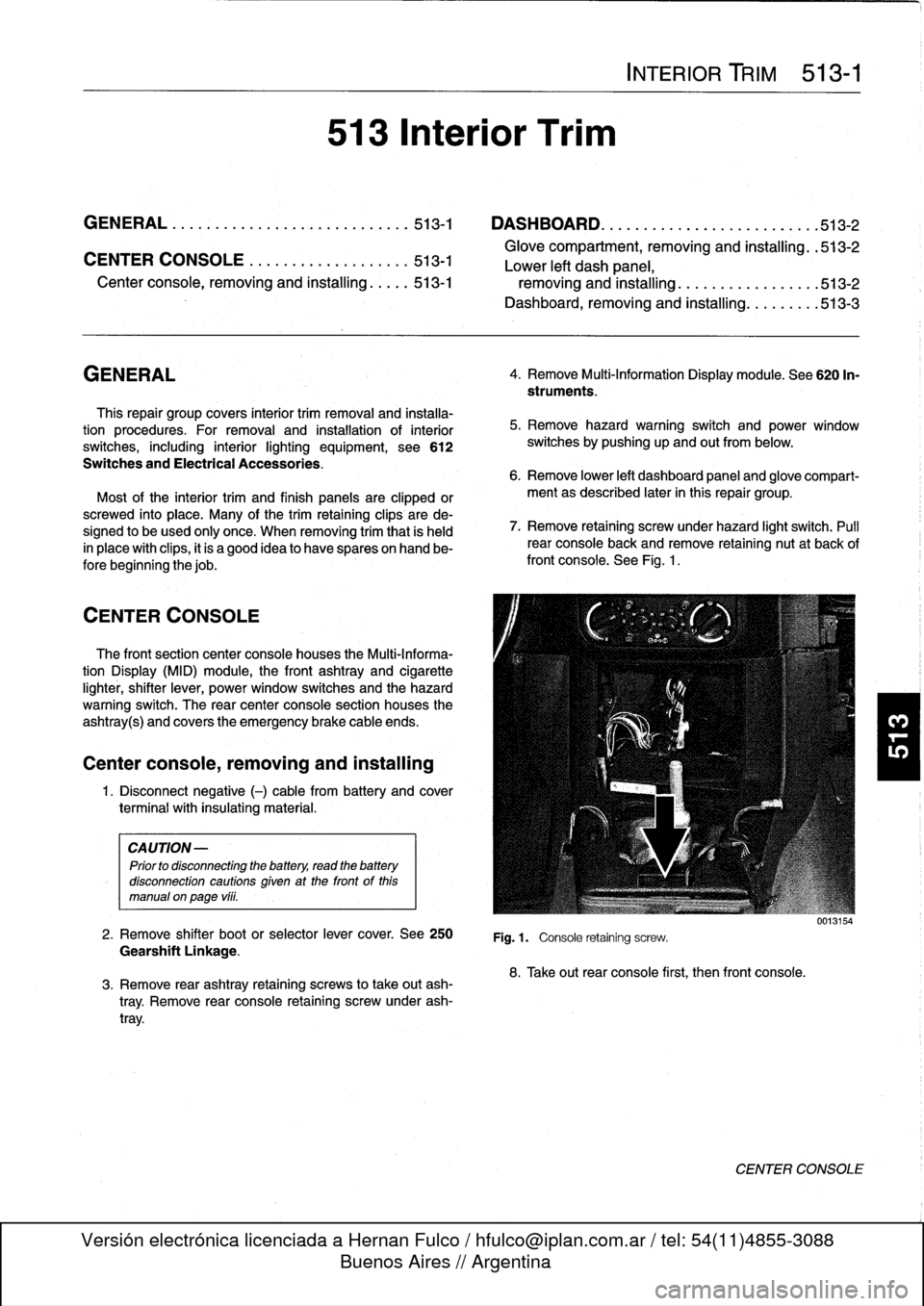
7
.
Remove
retaining
screwunder
hazard
light
switch
.
Pull
rear
console
back
and
remove
retaining
nut
at
back
of
front
console
.
See
Fig
.
1
.
Fig
.1.
Console
retaining
screw
.
8
.
Take
out
rear
console
first,
then
front
console
.
0013154
CENTER
CONSOLE
Page 347 of 759
Dashboard,
removing
and
installing
1
.
Disconnect
negative
(-)
cable
from
battery
and
cover
terminal
with
insulating
material
.
CAUTION-
Prior
to
disconnectiog
the
battery,
read
the
battery
disconnection
cautionsgiven
at
the
front
of
this
manual
onpage
vi¡¡
.
2
.
Remove
center
console
as
described
earlier
.
3
.
Remove
glove
compartment
as
described
earlier
.
4
.
Remove
lower
left
dash
trim
piece
as
described
above
.
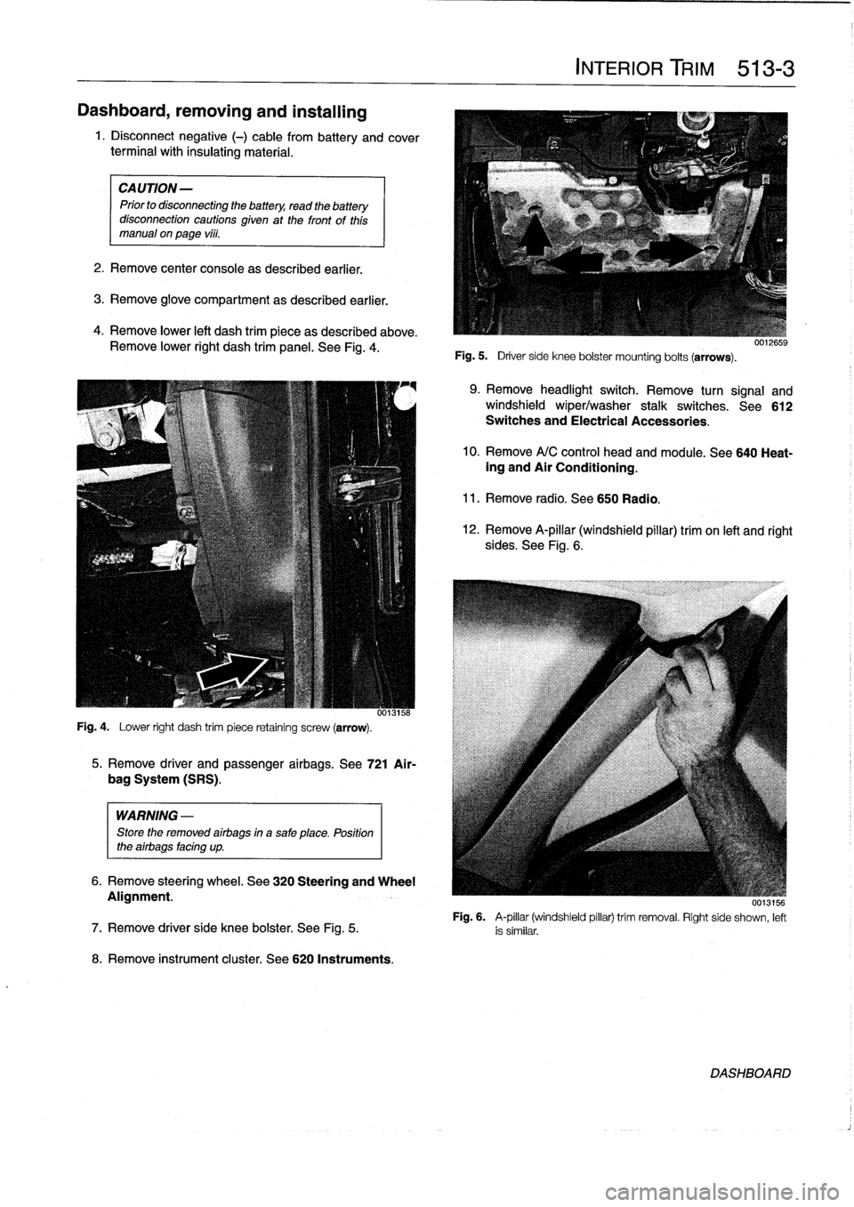
Remove
lower
right
dash
trim
panel
.
See
Fig
.
4
.
Fig
.
4
.
Lower
right
dash
trim
piece
retaining
screw
(arrow)
.
WARNING
-
Store
the
removed
airbags
in
a
safe
place
.
Position
the
airbags
facing
up
.
8
.
Remove
instrument
cluster
.
See
620
Instruments
.
5
.
Remove
driver
and
passenger
airbags
.
See
721
Air-
bag
System
(SRS)
.
6
.
Remove
steering
wheel
.
See
320
Steering
and
Wheel
Alignment
.
INTERIOR
TRIM
513-
3
Fig
.
5
.
Driver
side
knee
bolster
mounting
bolts
(arrows)
.
9
.
Remove
headlight
switch
.
Remove
turn
signal
and
windshield
wiper/washer
stalk
switches
.
See612
Switches
and
Electrical
Accessories
.
10
.
Remove
A/C
control
head
and
module
.
See
640
Heat-ing
and
Air
Conditioning
.
11
.
Remove
radio
.
See650
Radio
.
12
.
Remove
A-pillar
(windshield
pillar)
trim
on
left
and
right
sides
.
See
Fig
.
6
.
UU13156
Fig
.
6
.
A-pillar
(windshield
pillar)
trim
removal
.
Right
side
shown,
left
7
.
Remove
driver
side
knee
bolster
.
See
Fig
.
5
.
is
similar
.
DASHBOARD
Page 354 of 759
515-6
CENTRAL
LOCKING
AND
ANTI-THEFT
6
.
Remove
door
handle
assembly
from
inside
door
.
7
.
Installation
is
reverse
of
removal
.
Keep
in
mindthe
fol-
lowing
:
"
Make
sure
rubber
seal
for
handle
is
correctly
posi-
tionedbefore
tightening
mounting
fasteners
.
"
Install
exterior
trim
piece
and
then
use
a
hooked
toolto
pull
locking
plate
into
locked
position
.
Make
sure
door
handle
trim
contacts
body
evenly
before
lockingtrim
in
place
.
"
Reconnect
all
harness
connectors
(including
power
window
motor)before
installing
door
panel
.
"
Secure
wire
harnesses
withwire
ties
.
"
Adjust
windowas
described
in
512
Door
Windows
.
Tightening
Torque
"
Rear
door
handle
mounting
screws
..
10
Nm
(89
in-lb)
NOTE
If
the
striker
backup
plate
fafls
into
the
body
cavlty,
it
can
be
retrieved
after
removing
the
inside
trim
from
the
B-pillar
(door-post
pillar)
.
Tightening
Torque
"
Striker
plate
to
body
pillar
..........
28
Nm
(20
ft-lb)
LOCKING
ACTUATORS
Door
Locking
Actuator
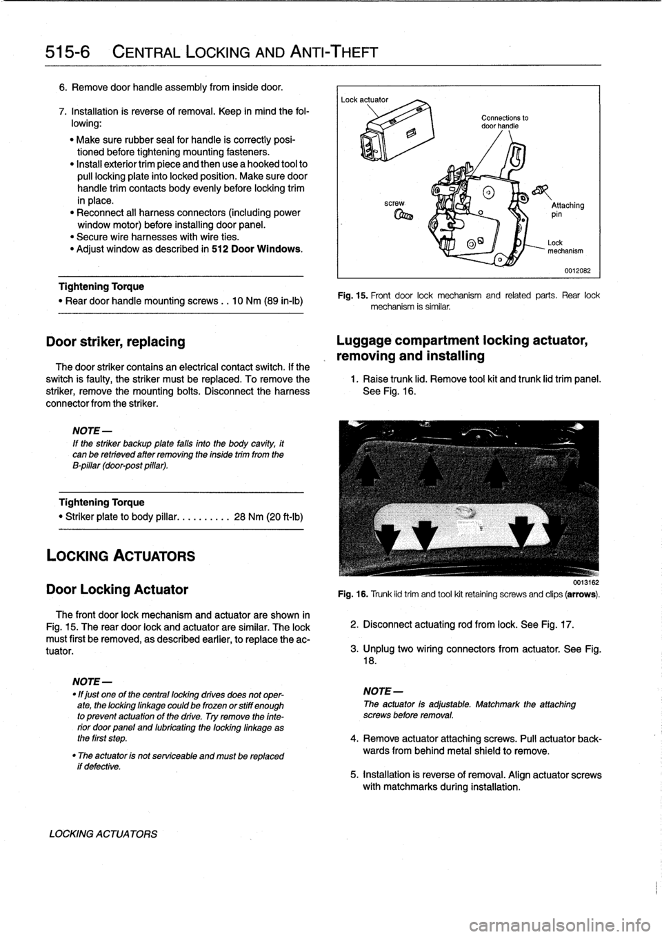
The
front
door
lock
mechanism
and
actuator
are
shown
in
Fig
.
15
.
The
rear
door
lock
and
actuator
are
similar
.
The
lock
must
first
be
removed,
as
described
earlier,
to
replace
the
ac-
tuator
.
if
defective
.
LOCKING
ACTUATORS
Connections
to
door
handle
®
o
_
Attaching
pin
0
O~
Lock
mechanism
0012082
Fig
.
15
.
Front
door
lock
mechanism
and
related
parts
.
Rear
lock
mechanism
is
similar
.
Door
striker,
replacing
Luggage
compartment
locking
actuator,
removing
and
installing
The
door
striker
contains
an
electrical
contact
switch
.
If
the
switch
is
faulty,
the
striker
must
be
replaced
.
To
remove
the
1
.
Raise
trunk
lid
.
Remove
tool
kit
and
trunk
lid
trim
panel
.
striker,
remove
the
mounting
bolts
.
Disconnect
the
harness
See
Fig
.
16
.
connector
from
the
striker
.
0013162
Fig
.
16
.
Trunk
lid
trim
and
tool
kit
retainíng
screws
and
clips
(arrows)
.
2
.
Disconnect
actuating
rod
from
lock
.
See
Fig
.
17
.
3
.
lJnplug
two
wíring
connectors
from
actuator
.
See
Fig
.
18
.
NOTE
-
"
lf
just
one
of
the
centrallocking
drives
does
not
oper-
NOTE-
ate,
the
lockinglinkage
could
be
frozen
orstiff
enough
The
actuator
is
adjustable
.
Matchmark
the
attaching
to
prevent
actuatonof
the
drive
.
Try
remove
the
finte-
screws
before
removal
.
rior
doorpanel
and
lubricating
the
locking
linkage
as
the
first
step
.
4
.
Remove
actuator
attaching
screws
.
Pull
actuator
back-
"
The
actuator
is
not
serviceable
and
mustbe
replaced
wards
from
behind
metal
shield
to
remove
.
5
.
installation
is
reverse
of
removal
.
Align
actuator
screws
with
matchmarks
during
installation
.