switch BMW 318i 1997 E36 Repair Manual
[x] Cancel search | Manufacturer: BMW, Model Year: 1997, Model line: 318i, Model: BMW 318i 1997 E36Pages: 759
Page 182 of 759
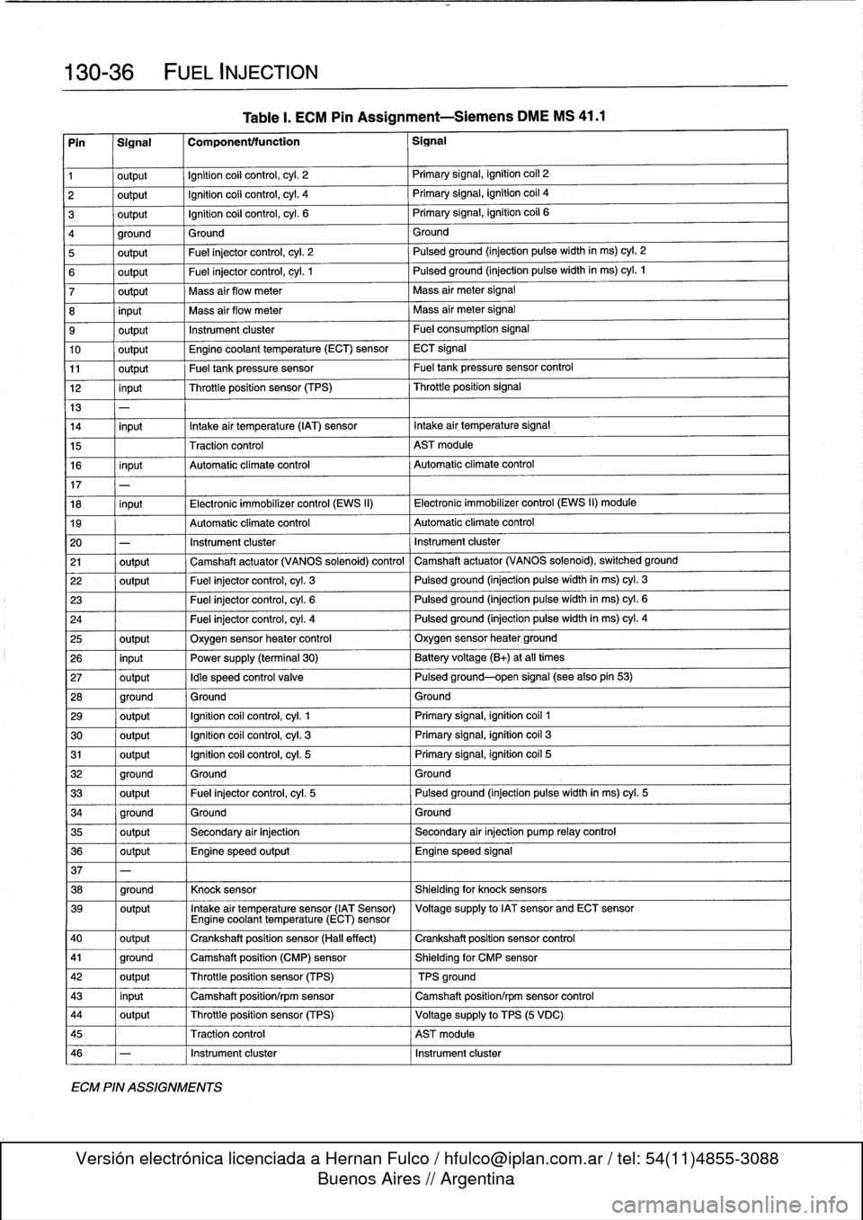
130-
3
6
FUEL
INJECTION
Pin
1
Signal
1
Componentffunction
1
Signal
1
output
Ignition
coil
control,
cyl
.
2
Primary
signal,
ignition
coil
2
2
output
Ignition
coil
control,
cyl
.
4
Primary
signal,
ignitioncoil
4
3
output
Ignition
coil
control,
cyl
.
6
Primary
signal,
ignition
coil
6
4
ground
Ground
Ground
5
output
Fuel
injectorcontrol,
cyl
.
2
Pulsed
ground
(injection
pulse
width
in
ms)
cyl
.
2
6
output
Fuel
injectorcontrol,
cyl
.
1
Pulsed
ground
(injection
pulse
width
in
ms)
cyl
.
1
7
output
Mass
air
flow
meter
Mass
air
meter
signal
8
input
Mass
air
flow
meter
Mass
air
meter
signal
9
output
Instrument
cluster
Fuel
consumption
signal
10
output
Engine
coolant
temperature
(ECT)
sensor
ECT
signal
11
output
Fueltankpressure
sensor
Fueltankpressure
sensor
control
12
input
Throttleposition
sensor
(TPS)
Throttleposition
signal
13
-
14
input
Intake
air
temperature
(IAT)
sensor
Intake
air
temperature
signal
15
Traction
control
AST
module
16
input
Automatic
climate
control
Automatic
climate
control
17
18
input
Electronic
immobilizer
control
(EWS
II)
Electronic
immobilizer
control
(EWS
II)
module
19
Automatic
climate
control
Automatic
climate
control
20
-
Instrument
cluster
Instrument
cluster
21
output
Camshaft
actuator
(VANOS
solenoid)
control
Camshaft
actuator
(VANOS
solenoid),
switched
ground
22
output
Fuel
injectorcontrol,
cyl
.
3
Pulsed
ground
(injection
pulse
width
in
ms)
cyl
.
3
23
Fuel
injectorcontrol,
cyl
.
6
Pulsed
ground
(injection
pulse
width
in
ms)
cyl
.
6
24
Fuel
injectorcontrol,
cyl
.
4
Pulsed
ground
(injection
pulse
width
in
ms)
cyl
.
4
25
output
Oxygen
sensor
heater
control
Oxygen
sensor
heater
ground
26
input
Power
supply
(terminal
30)
Battery
voltage(B+)
at
all
times
27
output
Idle
speed
control
valve
Pulsed
ground-open
signal
(see
also
pin
53)
28
ground
Ground
Ground
29
output
Ignition
coil
control,
cyl
.
1
Primary
signal,
ignition
coíl
1
30
output
Ignition
coil
control,
cyl
.
3
Primary
signal,
ignition
coil
3
31
output
Ignition
coil
control,
cyl
.
5
Primary
signal,
ignition
coil
5
32
ground
Ground
Ground
33
output
Fuel
injector
control,
cyl
.
5
Pulsedground
(injection
pulsewidth
in
ms)
cyl
.
5
34
ground
Ground
Ground
35
output
Secondary
air
injection
Secondary
air
injection
pump
relay
control
36
output
Engine
speed
output
Engine
speed
signal
37
-
38
ground
Knock
sensor
Shielding
for
knock
sensors
39
output
Intake
air
temperature
sensor
(IAT
Sensor)
Voltagesupply
to
IAT
sensor
and
ECT
sensorEngine
coolant
temperature
(ECT)
sensor
40
output
Crankshaft
position
sensor
(Hall
effect)
Crankshaft
position
sensor
control
41
ground
Camshaft
position
(CMP)
sensor
Shielding
for
CMP
sensor
42
output
Throttle
position
sensor
(TPS)
TPS
ground
43
input
Camshaft
position/rpm
sensor
Camshaft
position/rpm
sensor
control
44
output
Throttle
position
sensor
(TPS)
Voltagesupply
to
TPS
(5
VDC)
45
Traction
control
AST
module
46
-
Instrument
cluster
Instrument
cluster
ECM
PIN
ASSIGNMENTS
Table
I.
ECM
Pin
Assignment-Siemens
DME
MS
41
.1
Page 183 of 759
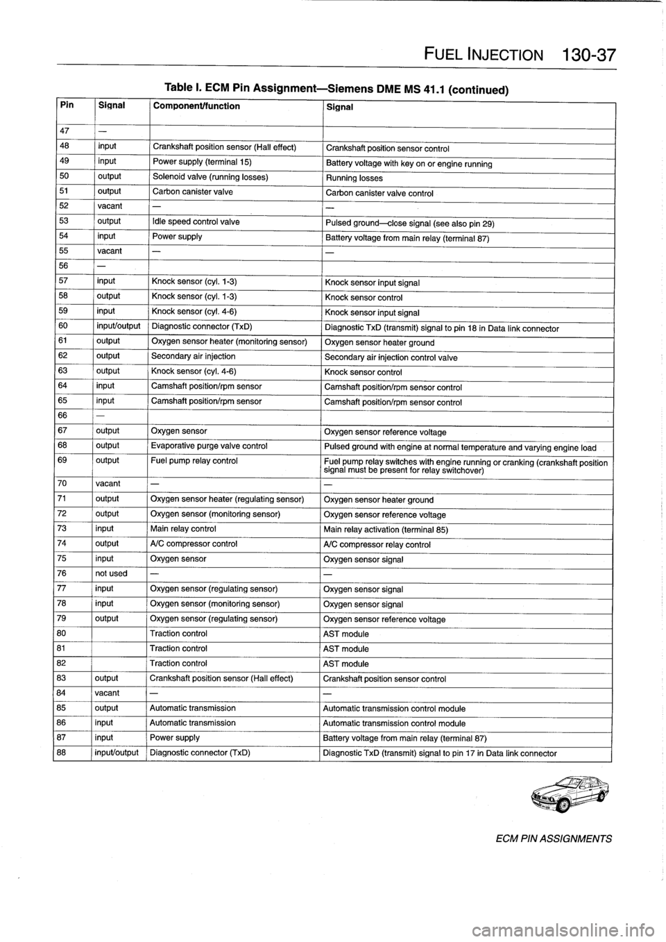
Table
I
.
ECM
Pin
Assignment-Siemens
DME
MS
41
.1
(continued)
Pin
I
Signal
I
Component/function
1
Signal
FUEL
INJECTION
130-
37
47
-
48
input
Crankshaft
position
sensor
(Hall
effect)
Crankshaft
position
sensor
control
49
input
Power
supply
(terminal
15)
Batteryvoltage
with
key
onor
engine
running
50
output
Solenoid
valve
(running
losses)
Running
losses
51
output
Carbon
canister
valve
Carbon
canister
valve
control
52vacant
-
53
output
Idle
speed
control
valve
Pulsed
ground-close
signal
(seealsopin29)
54
input
Power
supply
Battery
voltagefrom
main
relay
(terminal
87)
55
vacant
-
56
-
57
input
Knock
sensor
(cyl
.
1-3)
Knock
sensor
input
Signal
58
output
Knock
sensor
(cyl
.
1-3)
Knock
sensor
control
59
input
Knock
sensor
(cyl
.
4-6)
Knock
sensor
input
Signal
60
input/output
Diagnostic
connector
(TxD)
Diagnostic
TxD
(transmit)
signal
to
pin
18
in
Data
link
connector
61
output
Oxygen
sensor
heater
(monitoring
sensor)
Oxygen
sensor
heater
ground
62
output
Secondary
air
injection
Secondary
air
injection
control
valve
63
output
Knock
sensor
(cyl
.
4-6)
Knock
sensor
control
64
input
Camshaft
position/rpm
sensor
Camshaft
position/rpm
sensor
control
65
input
Camshaft
position/rpm
sensor
Camshaft
position/rpm
sensor
control
66
-
67
output
Oxygen
sensor
Oxygen
sensor
reference
voltage
68
output
Evaporative
purge
valve
control
Pulsed
ground
with
engine
at
normal
temperature
and
varyingengine
load
69
output
Fuel
pump
relay
control
Fuel
pump
relay
switches
with
engine
runningorcranking
(crankshaft
position
signal
must
be
present
for
relay
switchover)
70
vacant
-
-
71
output
Oxygen
sensor
heater
(regulating
sensor)
Oxygen
sensor
heater
ground
72
output
Oxygen
sensor
(monitoring
sensor)
Oxygen
sensor
referencevoltage
73
input
Main
relay
control
Main
relay
activation
(terminal
85)
74
output
A/C
compressor
control
A/C
compressor
relay
control
75
input
Oxygen
sensor
Oxygen
sensor
signal
76
not
used
-
-
77
input
Oxygen
sensor
(regulating
sensor)
Oxygen
sensor
signal
78
input
Oxygen
sensor
(monitoring
sensor)
Oxygen
sensor
signal
79
output
Oxygen
sensor
(regulating
sensor)
Oxygen
sensor
referencevoltage
80
Traction
control
AST
module
81
Traction
control
AST
module
82
Traction
control
AST
module
83
output
Crankshaft
position
sensor
(Hall
effect)
Crankshaft
position
sensor
control
84
vacant
-
-
85
output
Automatic
transmission
Automatic
transmission
control
module
86
input
Automatic
transmission
Automatic
transmissíon
control
module
87
input
Power
supply
Battery
voltage
from
main
relay
(terminal
87)
88
input/output
Diagnostic
connector
(TxD)
Diagnostic
TxD
(transmit)
signal
to
pin
17
in
Data
link
connector
ECM
PIN
ASSIGNMENTS
Page 190 of 759
160-
6
FUEL
TANK
AND
FUEL
PUMP
Fig
.
7
.
Fuel
sender
and
pump
assembly
.
To
operate
the
fuel
pump
for
testing
purposes
without
hav-
Fuel
leve¡
sender
(left
side),
ing
to
runthe
engine,
the
fuel
pump
relay
can
be
bypassed
to
removing
and
installing
powerthe
pump
directly
.
The
procedure
for
removing
and
replacing
the
left
side
fuel
To
runthe
fuel
pump,
remove
the
relay
and
connect
the
leve¡
sender
is
similar
tothat
used
for
the
right
side
.
There
is
socket
for
relayterminal
30
to
the
socket
for
relay
terminal
no
.
no
fuel
pump
on
the
left
side
.
87
with
afused
jumper
wire
.
Relay
terminal
identification
is
shown
in
Fig
.
9
.
After
completing
the
tests,
remove
the
jumper
wire
.
FUEL
PUMP
The
electric
fuel
pump
ís
mounted
in
the
fuel
tank
in
tandem
with
the
right
side
fuelleve¡
sender
.
The
fuel
pump
delivers
fuel
at
high
pressure
to
the
fuel
injection
system
.
A
pressure
regulator
maintains
system
pressure
.
The
quantity
of
fuel
sup-
plied
exceeds
demand,
so
excess
fuel
retums
to
the
fuel
tank
via
a
retum
líne
.
See
130
Fuel
Injection
for
more
information
on
system
pressure
and
the
fuel
pressure
regulator
.
NOTE
-
Fuel
pump
removalprocedures
are
given
earlier
under
Fuel
leve¡
sender
(right
side)
and
fuel
pump,
remov-
íng
and
installing
.
Fuel
Pump
Fuse
and
Relay
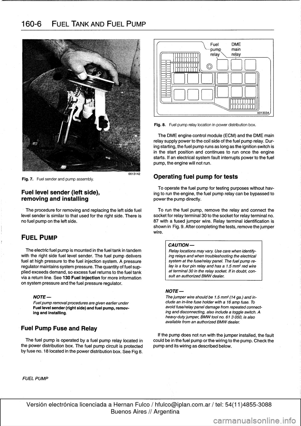
The
fuel
pump
is
operated
by
a
fuel
pump
relay
located
ín
the
power
distribution
box
.
The
fuel
pump
circuit
is
protected
by
fuse
no
.
18
located
in
the
power
distribution
box
.
See
Fig
8
.
FUEL
PUMP
0013142
Fuel
DM
E
PUMP
main
re
ay
rel
ay
0
aoo
o
~a
aao
ó
Fig
.
8
.
Fuel
pump
relay
location
in
power
distribution
box
.
The
DME
engine
control
module
(ECM)
and
the
DME
main
relay
supply
power
to
the
coi¡
sideof
the
fuel
pump
relay
.
Dur-
ing
starting,
the
fuel
pump
runs
as
long
as
the
ignition
switch
is
in
the
start
position
and
continues
to
run
oncethe
engine
starts
.
If
an
electrical
system
fault
interrupts
power
to
the
fuel
pump,
the
engine
will
notrun
.
Operating
fuel
pump
for
tests
CA
UTION-
Relay
locations
may
vary
.
Use
care
when
identify-
ing
relays
and
when
troubleshooting
the
electrical
system
at
the
fuselrelay
panel
.
The
fuel
pump
re-
¡ay
is
a
four
pin
relay
and
has
a
1.5
mm
2
red
wireat
terminal
30
in
the
relay
socket,
lf
in
doubt,
con-
sult
an
authorized
BMW
dealer
.
NOTE-
Thejumper
wire
shouldbe
1.5
mm2
(14
ga
.)
and
in-
clude
en
in-fine
fuse
holder
with
a16
amp
fuse
.
To
avoid
fuselrelay
panel
damage
fromrepeated
connect-
íng
and
disconnecting,
also
include
a
toggleswitch
.
A
heavy-duty
jumper,
BMW
tool
no
.
613
050,
fs
also
available
from
en
authorized
BMW
dealer
.
0013034,
If
the
pump
does
notrun
with
the
jumper
installed,
the
fault
could
be
in
the
fuel
pump
or
the
wiring
to
the
pump
.
Check
the
pump
and
its
wiring
as
described
below
.
Page 195 of 759
170
Radiator
and
Cooling
System
GENERAL
.
.
.....
.
...
.
.
.
.
.
....
.
.
.
.
.
.
.
.170-1
Coolant
Pump
and
Thermostat
........
.
.
.
.
170-1
Radiator
and
Expansion
Tank
.........
.
...
170-1
Cooling
Fans
.
....
.
.
.
.
.
.
.
.
.
.....
.
......
170-2
Warnings
and
Cautions
.
.
.
.
.
.
.
.
.
.
.
.
...
.
.
.
170-2
TROUBLESHOOTING
...
.
.
.
...
.
.
.
.
.
.
.
.
.170-2
Cooling
System
Pressure
Test
...
.
.
.
.
.
.
.
.
.
170-3
Thermostat
Quick
Check
.
.
.
.
...
.
.
.
.
.
.
.
.
.
170-3
Temperature
Gauge
Quick
Check
.
.
.
.
.
.
.
.
.
170-3
Cooling
fan,
testing
.
.
.
.
........
.
.
.
.
.
.
.
.
.
170-4
COOLING
SYSTEM
SERVICE
.
.
.
.
.
.
.
.
.
.
170-5
Coolant,draining
and
filling
.
.
......
.
.
.
.
.
..
170-5
Cooling
system,
bleeding
(radiator
with
integral
expansion
tank)
.....
170-6
GENERAL
This
section
covers
repair
and
troubleshooting
information
for
the
engine
cooling
system
.
For
heater
core
and
related
heating
and
air
conditioning
components,
see640
Heating
and
Air
Conditioning
.
Coolant
Pump
and
Thermostat
A
centrifuga¡-type
coolant
pump
is
mounted
to
the
front
of
the
engíne
.
The
belt-driven
pump
circulates
coolant
through
the
system
whenever
the
engíne
is
running
.
A
thermostat
con-
trols
the
flow
of
coolant
into
the
radiator
.
When
the
engíne
is
cold
the
thermostat
is
closed
so
coolant
bypasses
the
radiator,
recirculating
from
the
engíne
directly
back
to
the
pump
.
When
the
engíne
reaches
operating
tem-
perature,
the
thermostat
opens
and
coolant
circulates
through
the
whole
system
including
the
radiator
.
Radiator
and
Expansion
Tank
The
radiator
is
a
crossflow
design
.
A
translucent
expansion
tank
provides
for
coolant
expansion
at
higher
temperatures
and
easy
monitoringof
the
coolant
leve¡
.
On
4-cylinder
modeis,
the
radiator
expansion
tank
is
integral
with
the
radiator
.
See
Fig
.
1
.
RADIATOR
AND
COOLING
SYSTEM
170-1
Belt-driven
cooling
fan,
replacing
.
.......
.
.
.
170-7
Electric
cooling
fan,
replacing
.
.
.
.....
.
.
.
.
.
170-8
Auxiliary
cooling
fan,
replacing
.
.
.....
.
.
.
.
.
170-8
Thermostat,
replacing
.
.
.
.
.
.
.
.
.
.....
.
.
.
.
.
170-9
Coolant
pump,
replacing
..........
.
.
.
.
.
.
170-10
RADIATOR
SERVICE
.....
.
......
.
.
.
.
.
.
170-11
Radiator,
removing
and
installing
....
.
.
.
.
.
.
170-11
TABLES
a
.
Coolant
Temperature
Sensor
Wire
Colors
...
.
..
.
.
170-3b
.
Auxiliary
Cooling
Fan
Switching
Temperatures
.:.
.170-4
c
.
Auxiliary
Cooling
Fan
Temperature
Switch
Tests
..
..
.
...
...
.
.............
.
..
.
.
170-5d
.
Cooling
System
Capacities
..............
..
.
.
.
170-6
A
.
Expansion
tank
C
.
Dualtemperature
fan
switch
B
.
Radiator
drain
screw
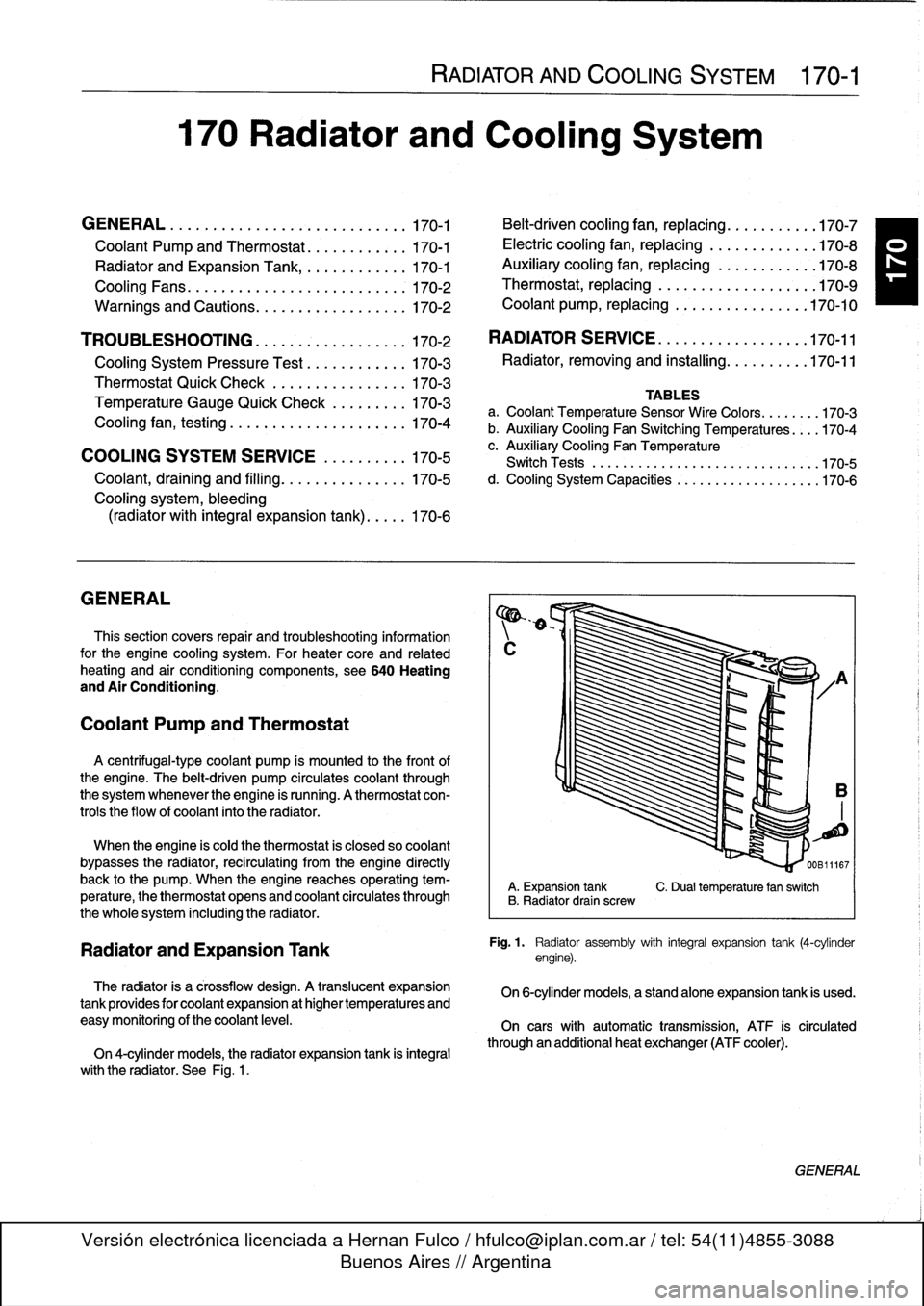
Fig
.
1
.
Radiator
assembly
with
integral
expansion
tank
(4-cylinder
engine)
.
On
6-cylinder
models,
a
standalone
expansion
tank
is
used
.
On
cars
with
automatic
transmission,
ATF
is
circulated
through
an
additional
heat
exchanger
(ATF
cooler)
.
GENERAL
Page 198 of 759
170-
4
RADIATOR
AND
COOLING
SYSTEM
A
quick
testat
the
coolant
temperature
gauge
sender
can
The
auxiliary
cooling
fan
comes
on
when
coolant
tempera
determine
if
the
gauge
is
functioning
correctly
.
ture
exceeds
a
predetermined
leve¡
or
whenever
the
air
condi-
tioning
is
on
.
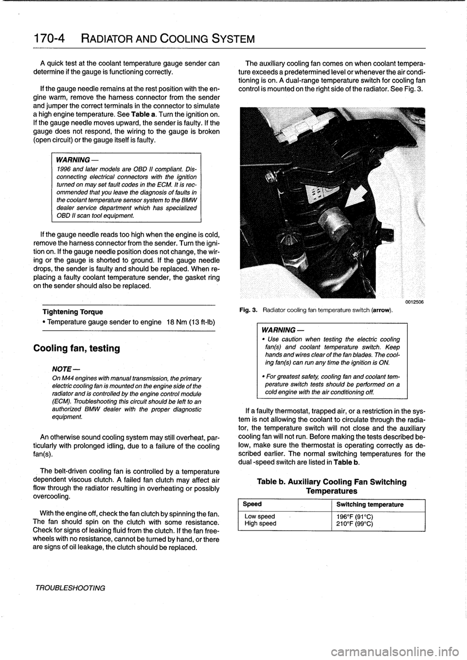
A
dual-range
temperature
switch
for
cooling
fan
lf
the
gauge
needie
remains
at
the
rest
position
with
theen-
control
is
mounted
on
the
right
side
of
the
radiator
.
See
Fig
.
3
.
gine
warm,
remove
the
harness
connector
from
the
sender
and
jumper
the
correct
terminals
in
the
connector
to
simulate
a
high
engine
temperature
.
See
Table
a
.
Turn
the
ignition
on
.
If
the
gauge
needle
moves
upward,
the
sender
is
faulty
.
If
the
gauge
does
not
respond,
the
wiring
to
the
gauge
is
broken
(open
circuit)
or
the
gauge
itselfis
faulty
.
WARNING
-
1996
and
laten
models
are
OBD
11
compliant
.
Dis-
connecting
electrical
connectors
wíth
the
ignition
turned
on
may
set
fault
codes
in
the
ECM
.
It
is
rec-
ommended
that
you
leave
the
diagnosis
of
faults
in
the
coolant
temperature
sensorsystem
to
the
BMW
dealer
service
department
which
has
specialized
OBD
11
scan
tool
equipment
.
If
the
gauge
needle
reads
too
high
when
the
engine
is
cold,
remove
the
harness
connector
from
the
sender
.
Turn
the
igni-
tion
on
.
lf
the
gauge
needle
position
does
not
change,
the
wir-
ing
or
the
gauge
is
shorted
to
ground
.
If
the
gauge
needle
drops,
the
sender
is
faulty
and
should
be
replaced
.
When
re-
placing
a
faulty
coolant
temperature
sender,
the
gasket
ring
on
the
sender
should
also
be
replaced
.
Tightening
Torque
"
Temperature
gauge
sender
to
engine
18
Nm
(13
ft-Ib)
Cooling
fan,
testing
NOTE-
OnM44
engines
with
manual
transmission,
the
primary
electric
cooling
fan
is
mounted
on
the
engine
side
of
the
radiator
and
is
controlled
by
the
engine
control
module
(ECM)
.
Troubleshooting
thiscircuit
should
be
left
to
an
authorized
BMW
dealer
with
the
proper
diagnostic
equipment
An
otherwise
sound
cooling
system
may
still
overheat,
par-
ticularly
with
prolonged
idling,
due
to
a
failure
of
the
coolíng
fan(s)
.
The
belt-driven
cooling
fan
is
controlled
by
a
temperature
dependent
viscous
clutch
.
A
failed
fan
clutch
may
affect
air
flow
through
the
radiator
resulting
in
overheating
orpossibly
overcooling
.
Speed
Low
sp
High
s
With
the
engine
off,
check
thefan
clutch
by
spinning
thefan
.
eed
The
fan
should
spin
on
the
clutch
with
some
resistance
.
peed
Check
for
signs
of
leaking
fluid
from
the
clutch
.
If
thefan
free-
wheels
with
no
resistance,
cannot
be
tu
rned
by
hand,
or
there
are
signs
of
oil
leakage,
the
clutch
should
be
replaced
.
TROUBLESHOOTING
Fig
.
3
.
Radiatorcooling
fan
temperature
switch
(arrow)
.
WARNING
-
"
Use
caution
when
testing
the
electric
cooling
fan(s)
and
coolant
temperature
switch
.
Keep
hands
and
wires
clear
of
thefan
blades
.
The
cool-
ing
fan(s)
can
run
any
time
the
ignition
is
ON
.
"
For
greatest
safety,
coolíng
fan
and
coolant
tem-perature
switch
tests
shouldbe
performed
on
acoldengine
with
the
air
conditioning
off
.
Table
b
.
Auxiliary
Cooling
Fan
Switching
Temperatures
Switching
temperature
196°F(91°C)
210°F(99°C)
0012506
If
a
faulty
thermostat,
trapped
air,
or
a
restriction
in
the
sys-
tem
is
not
allowing
the
coolant
to
circulate
through
the
radia-
tor,
the
temperature
switch
will
not
close
and
the
auxiliary
cooling
fan
will
not
run
.
Before
making
the
tests
described
be-
low,
make
sure
the
thermostat
is
operating
correctly
as
de-
scribed
earlier
.
The
normal
switching
temperatures
for
the
dual
-speed
switch
are
listed
in
Table
b
.
Page 199 of 759
NOTE-
Some
cars
covered
by
this
manual
may
have
an
alter-
nate
cooling
fan
switchwith
switching
temperatures
of
176%190W
(80%88°C)
.
When
replacing
the
switch
check
theswitching
specifications,
whichshouldbe
stamped
on
the
switch
body
.
1
.
If
coolant
is
circulating
at
normal
operating
tempera-
ture,
but
auxiliary
cooling
fan
does
not
run,
disconnect
connector
from
radiator
temperature
switch
and
make
tests
listed
in
Table
c
.
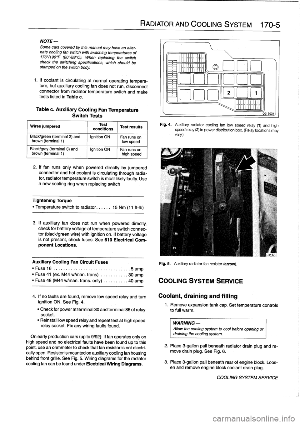
Table
c
.
Auxiliary
Cooling
Fan
Temperature
Switch
Tests
Wires
jumpered
Test
Test
resuits
conditions
Black/green
(terminal2)
and
Ignition
ON
Fan
runs
on
brown
(terminal
1)
low
speed
Black/gray
(terminal
3)
and
Ignition
ON
Fan
runson
brown
(terminal
I
1)
high
speed
2
.
If
fan
runs
only
when
powered
directly
by
jumpered
connector
and
hot
coolant
is
circulating
through
radia-
tor,
radiator
temperature
switch
is
most
likelyfaulty
.
Use
a
new
sealing
ring
when
replacing
switch
Tightening
Torque
"
Temperature
switch
to
radiator
......
15
Nm
(11
ft-Ib)
3
.
If
auxiliary
fan
does
notrun
when
powered
directly,
check
for
battery
voltage
at
temperature
switch
connec-
tor
(black/green
wire)
with
ignition
on
.
If
battery
voltage
is
not
present,
check
fuses
.
See
610
Electrical
Com-
ponent
Locations
.
RADIATOR
AND
COOLING
SYSTEM
170-
5
~r~nmm
a
00
0
Fig
.
4
.
Auxiliary
radiator
cooling
fan
low
speed
relay
(1)
and
high
speed
relay
(2)
in
power
distribution
box
.
(Relay
locations
may
vary
.)
Auxiliary
Cooling
Fan
Circuit
Fuses
Fig
.
5
.
Auxiliary
radiator
fan
resistor
(arrow)
.
"
Fuse16
.
...................
..
..
...
...
.5
amp
"
Fuse
41
(ex
.
M44
w/man
.
trans)
.
..
.
..
.....
30
amp
"
Fuse
48
(M44
w/man
.
trans
.
only)
..
.
..
.....
40
amp
COOLING
SYSTEM
SERVICE
0013034
4
.
If
no
faults
are
found,
remove
low
speed
relay
and
turn
Coolant,draining
and
filling
ignition
ON
.
See
Fig
.
4
.
1
.
Remove
expansion
tank
cap
.
Set
temperature
controls
"
Check
for
power
at
terminal
30
and
terminal
86
of
relay
to
full
warm
.
socket
.
"
Reinstall
low
speed
relay
and
repeat
testat
high
speed
WARNING
-
relay
socket
.
Fix
any
wiring
faults
found
.
Allow
the
cooling
system
to
cool
before
openlng
or
On
early
productioncars
(up
to
9/92)
:
If
fan
operates
only
on
draining
the
cooling
system
.
high
speed
and
no
electrical
faults
have
been
foundup
to
this
point,
usean
ohmmeter
to
check
that
fan
resistor
is
not
electri-
2
.
Place
3
ra
allo
ug
.
beneath
radiator
drain
plug
and
re-
cally
open
.
Resistor
is
mounted
on
auxiliary
cooling
fan
housing
move
drain
plg
.
See
Fig
.
6
.
behind
front
grille
.
See
Fig
.
5
.
Wiring
diagrams
for
the
radiator
cooling
fan
canbefoundunder
Electrical
Wiring
Diagrams
.
3
.
Place
3-g
pail
beneath
rear
of
engine
blo
.
Loos-
en
and
re
mlon
ove
engine
blockcoolant
drain
plug
k
.
COOLING
SYSTEM
SERVICE
Page 205 of 759
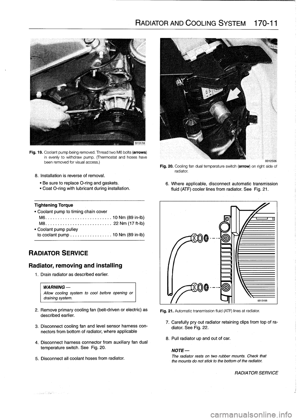
Fig
.
19
.
Coolant
pump
being
removed
.
Thread
two
M6
bolts
(arrows)
in
evenly
to
withdraw
pump
.
(Thermostat
and
hoseshavebeen
removed
tor
visual
access
.)
8
.
Installation
is
reverse
of
removal
.
"
Be
sure
to
replace
O-ring
and
gaskets
.
"
Coat
O-ring
with
lubricant
during
installation
.
Tightening
Torque
"
Coolant
pump
to
timing
chaincover
M6
...
.
...................
..
.
.
10
Nm
(89
in-lb)
M8
.
..
.
....................
.
.
.
22
Nm
(17
ft-Ib)
"
Coolant
pump
pulley
to
coolant
pump
.................
10
Nm
(89
in-lb)
RADIATOR
SERVICE
Radiator,
removing
and
installing
1
.
Drain
radiator
as
described
earlier
.
WARNING
-
Allow
cooling
system
to
cool
before
opening
ordraining
system
.
2
.
Remove
primary
cooling
fan
(belt-driven
or
electric)
as
described
earlier
.
3
.
Disconnect
coolingfan
and
leve¡
sensor
harness
con-
nectors
from
bottom
of
radiator,
where
applicable
4
.
Disconnect
harness
connector
from
auxiliary
fandual
temperature
switch
.
See
Fig
.
20
.
5
.
Disconnect
all
coolant
hoses
from
radiator
.
RADIATOR
AND
COOLING
SYSTEM
170-11
0012500
Fig
.
20
.
Cooling
fan
dual
temperatura
switch
(arrow)
on
right
sido
of
radiator
.
6
.
Where
applicable,
disconnectautomatic
transmission
fluid
(ATF)
cooler
lines
from
radiator
.
See
Fig
.
21
.
Fig
.
21
.
Automatic
transmission
fluid
(ATF)
linos
at
radiator
.
7
.
Carefully
pryout
radiator
retaining
clips
from
top
of
ra-
diator
.
See
Fig
.
22
.
8
.
Pul¡
radiator
up
and
out
of
car
.
NOTE-
The
radiator
rests
ontwo
rubber
mounts
.
Check
that
the
mounts
do
not
stick
to
the
bottomof
the
radiator
.
RADIATOR
SERVICE
Page 221 of 759
230
Manual
Transmission
MANUAL
TRANSMISSION
230-1
GENERAL
...
.
............
.
.......
.
.
.
.
230-1
Output
shaft
sea¡,
replacing
(transmission
installed)
....
.
.....
.
.....
.230-4
TRANSMISSION
FLUID
SERVICE
.
.
.
.
.
.
.230-1
Inputshaft
sea¡,
replacing
Transmission
fluid
leve¡,
checking
...
.
...
.
.
230-2
(transmission
removed)
.
.
.
.
...
.
.
.
.....
.
230-5
Transmission
fluid,
replacing
.........
.
.
.
.
230-2
TRANSMISSION
REMOVAL
AND
TRANSMISSION
SERVICE
.
.
.....
.
.
.
.
.
.
230-2
INSTALLATION
.
.
.
.
.
.
.....
.
.
.
.
.
.
.
.....
.
230-5
Back-up
light
switch,
replacing
.
.
.
...
.
.
.
.
.
.
230-2
Transmission,
removing
and
installing
...
.
.
.
.
230-6
_
Selector
shaft
sea¡,
replacing
(transmission
installed)
.
.
.
.
.
.
.
.
.
.
.
...
.
.
230-3
TAB
a
.
Manual
Transmission
Gear
Ratios
.
.
.
.........
.230-1
GENERAL
TRANSMISSION
FLUID
SERVICE
This
repair
group
covers
external
transmission
service,
in-
The
manual
transmissions
installed
in
the
E36
models
are
cluding
removal
and
installation
of
thetransmission
unit
.
Inter-
normally
filled
with
automatic
transmission
fluid
(ATF),
al-
nal
transmission
repair
is
not
covered
.
Special
press
tools
and
though
alternative
lubricants
may
have
beenused
from
the
procedures
are
required
to
disassemble
and
service
the
inter-
factory,
depending
on
transmission
type
and
model
year
.
For
nal
geartrain
.
example,
transmissions
fitted
to
the
M3
models
are
normally
filled
with
a
"lifetime"
manual
transmission
fluid
(BMW
MTF
Manual
transmissions
used
are
based
on
engine
applica-
LT-1)
and
do
not
require
periodic
fluid
changes
.
tion
.
Consult
200
Transmission-General
for
transmission
application
information
.
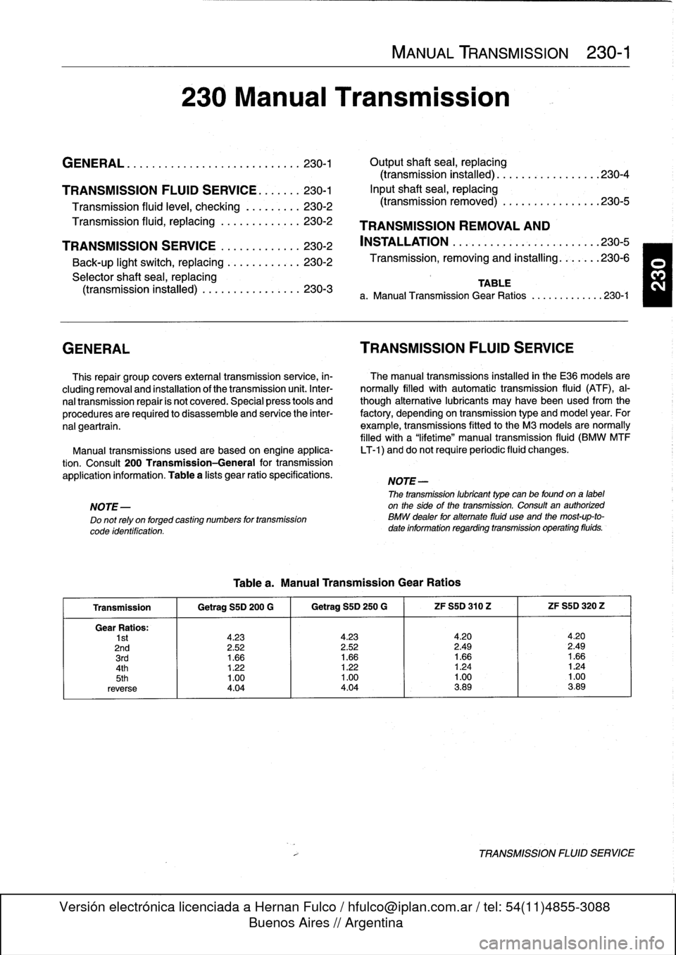
Table
a
lists
gear
ratio
specifications
.
NOTE-
The
transmission
lubricant
type
can
be
found
ona
label
NOTE-
on
the
sideof
the
transmission
.
Consult
an
authorized
Do
not
rely
on
forged
casting
numbers
for
transmission
BMW
dealer
for
altemate
fluid
use
and
the
most-up-to-
code
identification
.
date
information
regarding
transmission
operating
fluids
.
Tablea
.
Manual
Transmission
Gear
Ratios
Transmission
1
Getrag
S5D
200
G
1
Getrag
SSD
250
G
1
ZF
S5D
310
Z
1
ZF
S5D
320
Z
Gear
Ratios
:
1st
4
.23
4
.23
4
.20
4
.20
2nd
2
.52
2
.52
2
.49
2
.49
3rd
1
.66
1
.66
1
.66
1
.664th
1
.22
1
.22
1
.24
1
.24
5th
1
.00
1
.00
1
.00
1
.00
reverse
4
.04
4
.04
3
.89
3
.89
TRANSMISSION
FLUID
SERVICE
Page 222 of 759
230-2
MANUAL
TRANSMISSION
Transmission
fluidleve¡,
checking
Checking
thetransmission
oil
level
involves
simply
remov-
ing
the
side
drain
plug
and
inserting
a
finger
into
the
holeto
check
the
fluid
leve¡
.
lf
the
fluid
leve¡
is
up
to
the
bottom
of
the
drain
hole
(finger
is
wetted
by
transmission
fluid),
the
leve¡
is
correct
.
Transmission
fluid,
replacing
NOTE-
Manual
transmission
fluid
type
should
be
printed
ona
label
on
the
side
of
the
transmission
.
If
in
doubt,
consult
an
authorized
BMW
dealer
for
the
up-to-dateinforma-
tion
on
operating
fluids
.
1
.
Drive
vehicle
for
afew
miles
to
warm
transmission
.
2
.
Raise
and
safely
support
vehicle
to
access
drain
plug
.
WARNING
-
"
When
raising
the
car
uslng
a
floor
jack
or
a
hy-
draulic
lift,
carefully
position
the
jack
pad
to
pre-
vent
damaging
the
car
body
.
A
suitable
liner
(wood,
rubber,
etc
.)
should
be
placed
between
the
jack
and
the
car
to
prevent
body
damage
.
"
Watch
the
jack
closely
.
Make
sure
it
stays
stable
and
does
not
shíít
or
tilt
.
As
the
car
is
raised,
the
car
may
roll
slightly
and
the
jack
may
shift
.
3
.
Place
a
drain
pan
under
transmission
andremove
drain
plug
at
bottom
of
transmission
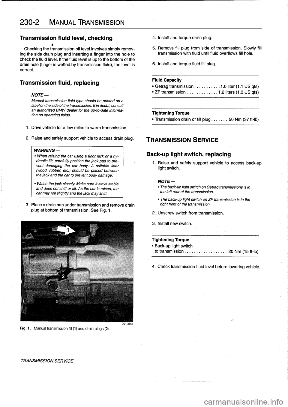
.
See
Fig
.
1
.
Fig
.
1
.
Manual
transmission
fill
(1)
and
drain
plugs
(2)
.
TRANSMISSION
SERVICE
4
.
Install
and
torque
drain
plug
.
5
.
Remove
fill
plug
from
side
of
transmission
.
Slowly
fill
transmission
with
fluiduntilfluid
overflows
fill
hole
.
6
.
Install
and
torque
fluid
fill
plug
.
Fluid
Capacity
"
Getrag
transmission
...........
1
.0
liter
(1.1
US
qts)
"
ZF
transmission
.............
1
.2
liters(1
.3
US
qts)
Tightening
Torque
"
Transmission
drain
or
fill
plug
.......
50
Nm
(37
ft-Ib)
TRANSMISSION
SERVICE
Back-up
light
switch,
replacing
1
.
Raise
and
safely
support
vehicle
to
accessback-up
light
switch
.
NOTE-
"
The
back-up
light
switch
on
Getrag
transmissions
is
in
the
left
rearof
the
transmission
.
"
Theback-up
light
switch
on
ZF
transmission
isin
the
rightfront
of
thetransmission
.
2
.
Unscrew
switch
from
transmission
.
3
.
Install
new
switch
.
Tightening
Torque
"
Back-up
light
switch
to
transmission
..
..
.
.....
.
..
.....
20
Nm
(15
ft-ib)
4
.
Check
transmission
fluid
leve¡
before
lowering
vehicle
.
Page 226 of 759
230-
6
MANUAL
TRANSMISSION
Transmission,
removing
and
installing
1
.
Disconnect
negative
(-)
cable
from
battery
.
CAUTION-
Prior
to
disconnecting
the
battery,
read
the
battery
disconnection
cautions
given
at
the
front
of
this
manual
onpage
viii
.
2
.
Insta¡¡
enginesupportacrossengine
bay
.
Raise
engine
so
that
weight
of
engine
ís
supported
.
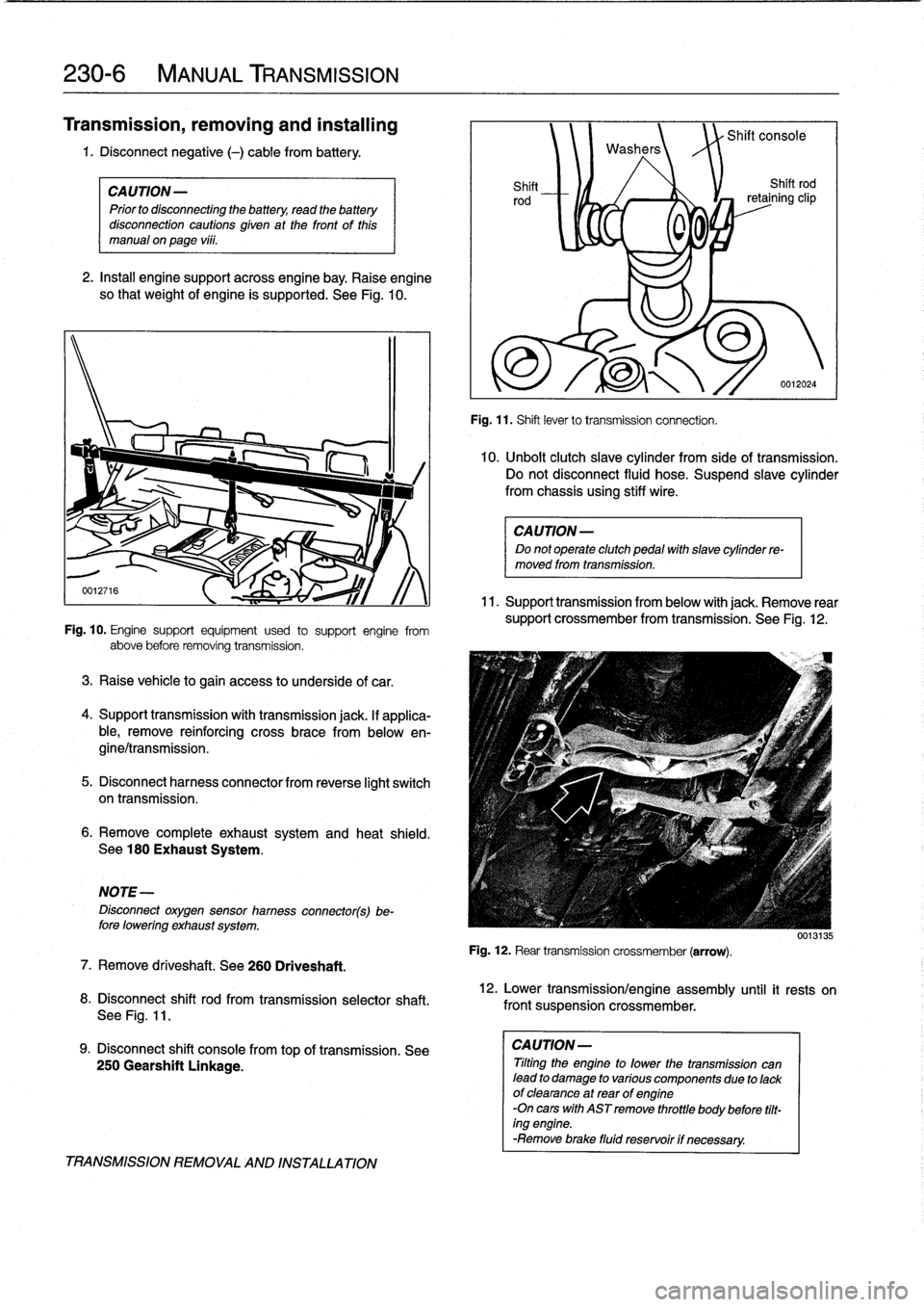
See
Fig
.
10
.
Fig
.
10
.
Engine
support
equipment
used
to
support
engine
from
above
before
removing
transmission
.
3
.
Raise
vehicle
to
gain
access
to
underside
of
car
.
4
.
Support
transmission
with
transmission
jack
.
lf
applica-
ble,
remove
reinforcing
cross
brace
from
belowen-
gine/transmission
.
5
.
Disconnect
harnesscon
nector
from
reverse
light
switch
on
transmission
.
6
.
Remove
completeexhaustsystem
and
heat
shield
.
See
180
Exhaust
System
.
NOTE-
Disconnect
oxygensensor
hamess
connector(s)be-
fore
lowering
exhaust
system
.
7
.
Remove
driveshaft
.
See260
Driveshaft
.
8
.
Disconnect
shift
rod
from
transmission
selectorshaft
.
See
Fig
.
11
.
9
.
Disconnect
shift
console
fromtop
of
transmission
.
See
250
Gearshift
Linkage
.
TRANSMISSION
REMOVAL
AND
INSTALLATION
Washers
Shift
Shift
rod
rod
retaining
clip
0
0
,
Fig
.
11
.
Shift
lever
to
transmission
connection
.
Shift
console
0012024
10
.
Unbolt
clutch
slave
cylinder
from
sideof
transmission
.
Do
not
disconnect
fluid
hose
.
Suspend
slavecylinder
from
chassis
using
stiff
wire
.
CAUTION-
Do
not
operate
clutch
pedal
with
slave
cylinder
re-
moved
from
transmission
.
11
.
Support
transmission
from
below
with
jack
.
Remove
rear
support
crossmember
from
transmission
.
See
Fig
.
12
.
Fig
.
12
.
Rear
transmission
crossmember
(arrow)
.
12
.
Lower
transmission/engine
assembly
until
it
rests
on
front
suspension
crossmember
.
CAUTION-
Tilting
the
engine
to
lower
thetransmission
can
lead
to
damage
to
various
componente
due
to
lackof
clearance
at
rear
of
engine
-On
cars
with
AST
remove
throttle
body
before
tilt-
ing
engine
.
-Remove
brace
fluid
reservoir
if
necessary
.
0013135