switch BMW 318i 1997 E36 Repair Manual
[x] Cancel search | Manufacturer: BMW, Model Year: 1997, Model line: 318i, Model: BMW 318i 1997 E36Pages: 759
Page 235 of 759
GENERAL
.
.
.
.
.
.
.
.
.
................
.
.
.
250-1
AUTOMATIC
TRANSMISSION
GEARSHIFT
...
.
.........
.
.
.
.
.
.
.
.
.
.
.
.
.
.
250-3
MANUAL
TRANSMISSION
Gearshift
mechanism,
adjusting
GEARSHIFT
.
.
.
.
.
.
.
.....
.
..........
.
.
.
250-1
(automatictransmission)
..
.
.
.
.
.
.
.
.
.
...
.
.
250-3
Gearshift
lever,
removing
Gear
position/neutral
safety
switch,
replacing
(manual
transmission)
.
.
.
.
...
.
.
.
.......
250-1
(automatic
transmission)
..
.
.
.
.........
.
.
250-4
Gearshift
lever,
installing
Automatic
shiftlock,
checking
function
(manual
transmission)
.
.
.
.
.
.
.
.
.
.
.......
250-2
(automatic
transmission)
..
..
...
.
.
.
....
..
250-5
Shiftinterlock,
checking
function
(automatic
transmission)
.......
.
.
.
.....
.250-6
GENERAL
This
repair
group
covers
transmission
gearshift
and
linkage
service
.
Special
service
tools
are
required
for
some
of
the
proce-
dures
given
here
.
To
gain
access
to
the
complete
gearshift
mechanism
ít
is
necessary
to
remove
the
exhaust
system
and
the
driveshaft
as
described
in
180
Exhaust
System
and260
Driveshaft
.
MANUAL
TRANSMISSION
GEARSHIFT
Gearshift
lever,
removing
(manual
transmission)
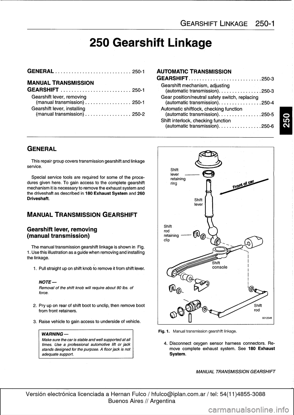
The
manual
transmission
gearshift
linkage
is
shown
in
Fig
.1
.
Use
thisillustration
asaguide
when
removing
and
installing
the
linkage
.
1
.
Pull
straight
upon
shift
knob
lo
remove
it
from
shift
lever
.
NOTE
-
Removal
of
the
shift
knob
will
require
about
90
lbs
.
of
force
.
2
.
Pry
upon
rear
of
shift
boot
tounclip,
then
remove
boot
from
front
retainers
.
3
.
Raise
vehicle
togain
access
to
underside
of
vehicle
.
WARNING
-
Make
sure
thecar
is
stable
and
well
supported
at
afl
times
.
Use
a
professional
automotive
lift
orjackstands
designed
for
the
purpose
.
A
floor
jack
is
not
adequate
support
.
250
Gearshift
Linkage
GEARSHIFT
LINKAGE
250-1
Fig
.1
.
Manual
transmission
gearshift
linkage
.
4
.
Disconnect
oxygen
sensorharness
connectors
.
Re-
move
completeexhaust
system
.
See
180
Exhaust
System
.
MANUAL
TRANSMISSION
GEARSHIFT
Page 237 of 759
2
.
Install
rubber
grommet
with
arrow
pointing
forward
.
In-
AUTOMATic
TRANSMISSION
stall
shift
rod
and
shift
boot
.
GEARSHIFT
NOTE-
Install
rubbergrommet
correctly
so
that
is
seals
outwa-
ter
.
4
.
Install
driveshaft
and
heat
shield
.
See
260
Driveshaft
.
Manual
valveleven
(at
transmission)
Fig
.
6
.
Automatic
transmission
gearshift
assembfy
.
Shift
cable
GEARSHIFT
LINKAGE
250-
3
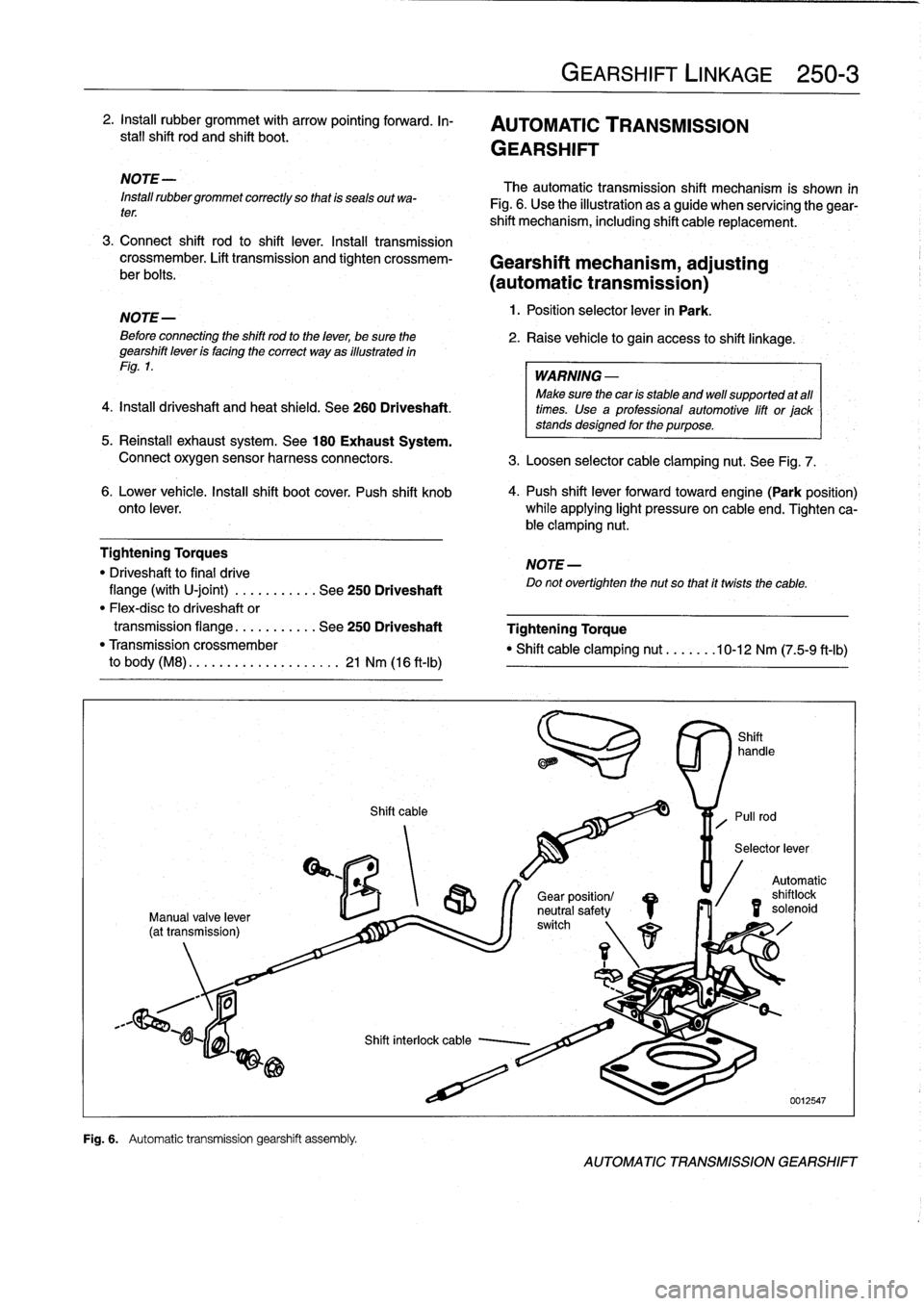
The
automatic
transmission
shift
mechanism
is
shown
in
Fig
.
6
.
Use
the
illustration
as
a
guide
when
servícing
the
gear-
shift
mechanism,
including
shift
cable
replacement
.
3
.
Connect
shift
rod
to
shift
lever
.
Install
transmission
crossmember
.
Lift
transmission
and
tighten
crossmem-
Gearshift
mechanism,
adjusting
ber
bolts
.
(automatictransmission)
NOTE-
1
.
Position
selector
lever
in
Park
.
Beforeconnecting
the
shift
rod
to
the
lever,
be
sure
the
2
.
Raise
vehicle
to
gain
access
to
shift
linkage
.
gearshift
leven
is
facing
the
correct
way
as
illustrated
in
Fig
.
1
.
WARNING
-
Make
sure
thecan
is
stable
and
well
supported
at
all
times
.
Use
a
professional
automotive
lift
or
jack
stands
designed
for
the
purpose
.
5
.
Reinstall
exhaust
system
.
See
180
Exhaust
System
.
Connect
oxygen
sensor
harness
connectors
.
3
.
Loosen
selector
cable
clamping
nut
.
See
Fig
.
7
.
6
.
Lower
vehicle
.
Insta¡¡
shift
boot
cover
.
Push
shift
knob
4
.
Push
shift
lever
forwardtoward
engine(Park
position)
onto
lever
.
while
applying
light
pressure
on
cable
end
.
Tighten
ca-
ble
clamping
nut
.
Tightening
Torques
NOTE-
"
Driveshaft
to
final
drive
Do
not
overtighten
the
nut
so
that
it
twists
the
cable
.
flange
(with
U-joint)
.
..
.
.....
.
.
See
250
Driveshaft
"
Flex-disc
to
driveshaft
or
transmission
flange
...
.
.......
See
250
Driveshaft
Tightening
Torque
"
Transmission
crossmember
"
Shift
cable
clamping
nut
.......
10-12
Nm
(75-9
ft-Ib)
to
body
(M8)
.
.
.
...
..............
21
Nm
(16
ft-Ib)
/S
r\
1
1
Gear
position/
neutral
safetyswitch
Automatic
shilo
solenoid
id
AUTOMATIC
TRANSMISSION
GEARSHIFT
Page 238 of 759
250-
4
GEARSHIFT
LINKAGE
r%
;
5
(((((C
"
~
;
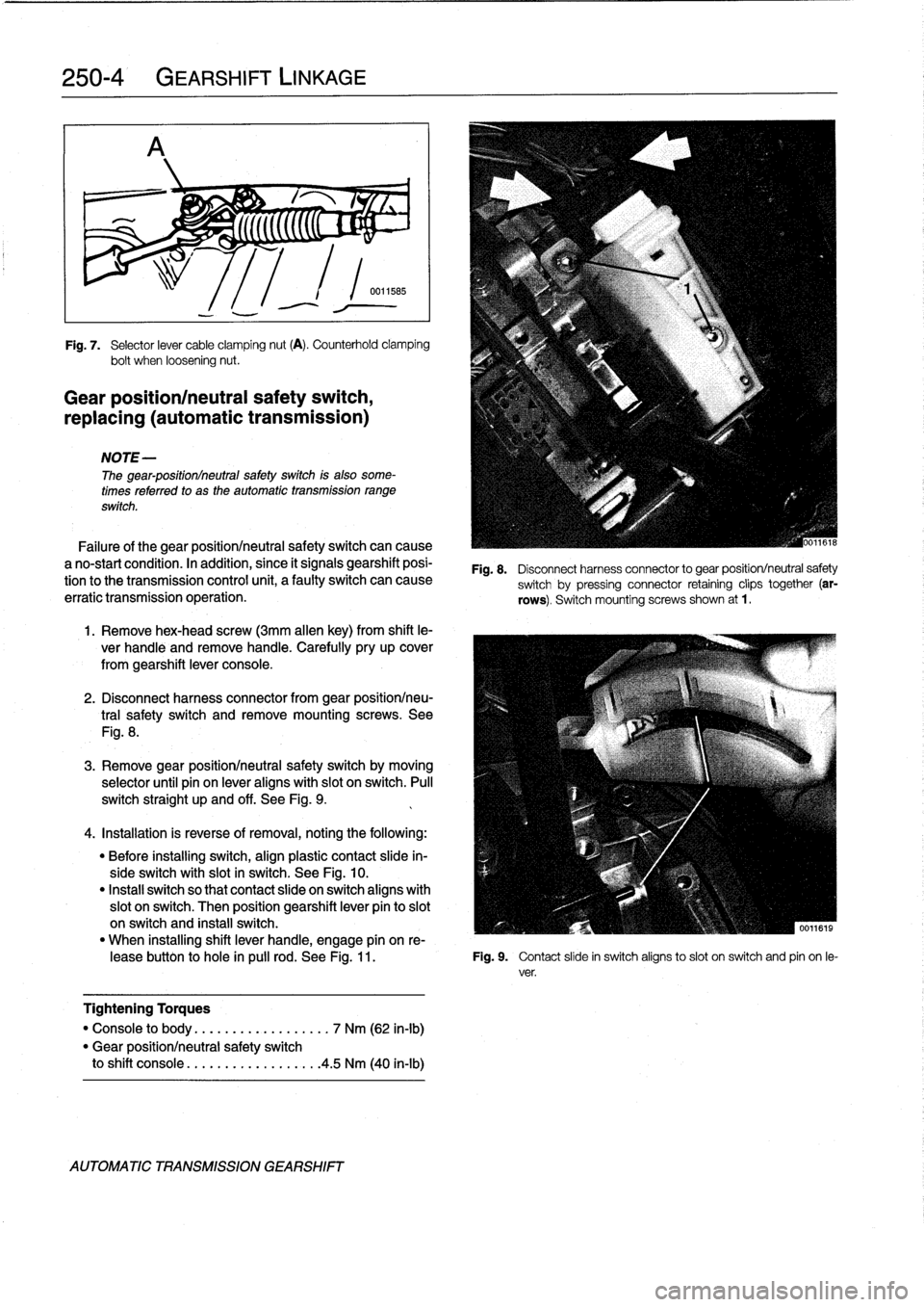
Fig
.
7
.
Selector
lever
cable
clamping
nut
(A)
.
Counterhold
clamping
bolt
when
loosening
nut
.
Gear
position/neutral
safety
switch,
replacing
(automatic
transmission)
NOTE-
The
gear-positionlneutral
safetyswitch
is
also
some-
times
referred
to
as
the
automatic
transmission
range
switch
.
Failure
of
the
gear
positionlneutral
safetyswitch
can
cause
a
no-start
condition
.
In
acidition,
since
it
signals
gearshift
posi-
tion
tothe
transmission
control
unit,
a
faulty
switch
can
cause
erratic
transmission
operation
.
1
.
Remove
hex-head
screw
(3mm
allen
key)
from
shift
le-
ver
handle
and
remove
handle
.
Carefully
pry
up
cover
from
gearshift
lever
console
.
2
.
Disconnect
harness
connector
from
gear
positionlneu-
tral
safety
switch
andremove
mounting
screws
.
See
Fig
.
8
.
3
.
Remove
gear
positionlneutral
safety
switch
by
moving
selector
until
pin
on
lever
aligns
with
slot
on
switch
.
Pull
switch
straight
up
and
off
.
See
Fig
.
9
.
4
.
Installation
is
reverse
of
removal,
noting
the
following
:
"
Before
installing
switch,
align
plastic
contact
slide
in-
sideswitch
with
slot
in
switch
.
See
Fig
.
10
.
"
Instan
switch
so
that
contact
slide
on
switch
aligns
with
slot
on
switch
.
Then
position
gearshift
lever
pin
to
slot
on
switch
and
install
switch
.
"
When
installing
shift
lever
handle,
engage
pín
on
re
leasebutton
to
hole
in
pulí
rod
.
See
Fig
.
11
.
Fig
.
9
.
Contact
slide
in
switch
aligns
toslot
on
switch
and
pin
on
le-
ver
.
Tightening
Torques
"
Console
to
body
..............
...
.
7
Nm
(62
in-lb)
"
Gear
positionlneutral
safety
switch
to
shift
console
.................
.
4
.5
Nm
(40
in-lb)
AUTOMATIC
TRANSMISSION
GEARSHIFT
Fig
.
8
.
Disconnect
harness
connector
to
gear
position/neutral
safety
switch
by
pressing
connector
retaining
clips
together
(ar-
rows)
.
Switch
mountingscrews
shown
at
1
.
Page 239 of 759
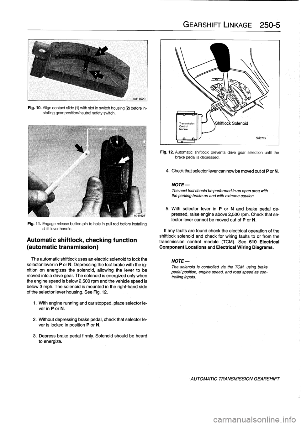
Fig
.
10
.
Align
contact
slide
(1)
with
slot
in
switch
housing
(2)
before
in-
stalling
gear
position/neutral
safety
switch
.
Fig
.
11
.
Engage
release
button
pin
to
hole
in
pull
rod
before
installing
The
automatic
shiftlock
uses
an
electríc
solenoid
to
lock
the
selector
lever
in
P
or
N
.
Depressing
the
foot
brake
withthe
ig-
nition
on
energizes
the
solenoid,
allowingthe
lever
to
be
moved
into
a
drive
gear
.
The
solenoid
is
energized
only
when
the
engine
speed
is
below
2,500
rpmand
thevehicle
speed
is
below
3
mph
.
The
solenoid
ís
mounted
in
the
right-hand
side
of
theselector
lever
housing
.
See
Fig
.
12
.
1
.
With
engine
running
and
car
stopped,
place
selector
le-
ver
in
P
or
N
.
2
.
Without
depressing
brake
pedal,
check
that
selector
le-
ver
is
locked
in
position
P
or
N
.
3
.
Depress
brakepedal
firmly
.
Solenoid
should
be
heard
to
energize
.
GEARSHIFT
LINKAGE
250-
5
Fig
.
12
.
Automatic
shiftlock
prevents
drive
gear
selection
until
the
brakepedal
is
depressed
.
4
.
Check
thatselector
lever
can
now
be
moved
out
of
P
or
N
.
NOTE
-
The
next
test
should
be
performed
in
anopen
area
with
the
parking
brake
on
and
with
extreme
caution
.
5
.
With
selector
lever
in
P
or
N
and
brake
pedal
de-
pressed,
raise
engine
above
2,500
rpm
.
Check
that
se-
lector
lever
cannotbe
moved
outof
P
or
N
.
shift
lever
handle
.
If
any
faults
are
found
check
the
electrical
operation
of
the
shiftlock
solenoid
and
check
for
wiring
faultsto
or
from
the
Automatic
shiftiock,
checking
function
transmission
control
module(TCM)
.
See610
Electrical
(automatic
transmission)
Component
Locations
and
Electrical
Wiring
Diagrams
.
NOTE
-
The
solenoid
is
controlled
viathe
TCM,
using
brakepedal
position,
engine
speed,
and
road
speed
as
con-
trolling
inputs
.
AUTOMATIC
TRANSMISSION
GEARSHIFT
Page 240 of 759
250-
6
GEARSHIFT
LINKAGE
Shift
interlock,
checking
function
1
.
Shift
selectorlever
to
park
(P)
position
and
turn
ignition
(automatic
transmission)
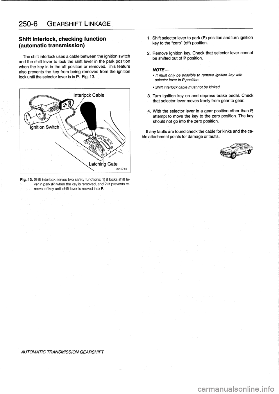
The
shift
interlock
usesa
cable
between
the
ignition
switch
and
the
shift
lever
to
lock
the
shift
lever
in
the
park
position
when
the
key
is
in
the
off
position
or
removed
.
This
feature
also
prevents
the
key
from
being
removed
from
the
ignition
lock
until
the
selectorlever
is
in
P
.
Fig
.
13
.
Fig
.
13
.
Shift
interlock
serves
two
safety
functions
:
1)
it
locks
shift
le-
ver
in
park
(P)
when
thekey
is
removed,
and
2)
it
prevents
re-
moval
of
key
untilshift
lever
is
moved
into
P
.
AUTOMATIC
TRANSMISSION
GEARSHIFT
Latchirig
Gate
0012714
key
to
the
"zero"
(off)
position
.
2
.
Remove
ignition
key
.
Check
that
selectorlever
cannot
be
shifted
out
of
P
position
.
NOTE-
"
lt
must
only
be
possible
to
remove
ignition
key
with
selector
lever
in
P
position
.
"
Shiftinterlock
cable
must
not
be
kinked
.
3
.
Turn
ignition
keyon
and
depressbrakepedal
.
Check
that
selectorlever
moves
freely
from
gear
to
gear
.
4
.
With
the
selectorlever
in
a
gear
position
other
than
P,
attempt
to
move
thekey
to
the
zero
position
.
The
key
shouldnot
go
into
the
zero
position
.
If
any
faults
arefound
check
the
cable
for
kinks
and
theca-
ble
attachment
points
for
damage
or
faults
.
Page 253 of 759
NOTE-
The
traction
control
system
referred
to
as
AST
(all
sea-
son
traction)
may
also
be
referred
to
as
ASC
(Automat-
ic
Stability
Control)
and
ASC+T
(Automatic
Stability
Control+Traction)
.
The
AST
system
improves
traction
by
electronically
apply-
ing
the
rear
brakes
when
therear
drive
wheels
are
spinning
at
a
faster
rate
than
the
front
wheels
.
The
combined
ABS/AST
control
module,
operating
through
the
ABS
hydraulic
control
unit,
modulates
braking
force
at
therear
wheels
.
In
addition,
AST
uses
retarded
ignition
timing
and
an
auxil-iary
engine
throttle
plate
to
reduceengine
torque
and
maintain
vehicle
stability
.
The
auxiliary
throttle
plate
is
held
open
by
spring
pressure
.
The
AST
system
actívates
the
auxiliary
throttie
position
motor
(ADS)
to
cose
the
AST
throttle
as
needed
.
This
reduces
the
volume
of
engine
intake
air
.
Due
to
the
throttle
closing
very
rapidly
during
AST
operationthe
driver
cannot
increase
theengine
power
output
regardless
of
how
far
theaccelerator
pedal
is
pushed
to
the
floor
.
The
auxiliary
throttle
plate
is
placed
ahead
of
the
conven-
tional
throttle
plate
in
the
throttle
body
.
Traction
control
also
comes
into
operationduringdecelera-
tion
.
Decelerating
on
snowy
or
icy
road
surfaces
can
lead
to
rear
wheel
slip
.
If
a
rear
wheel
startsto
drag
or
lock
up
when
the
throttle
is
closed
rapidly
orduringdownshifting,the
AST
system
can
limit
the
problem
by
advancing
the
ignition
timing
.
A
switch
on
the
center
console
is
used
to
togglethe
AST
on
or
off
.
The
AST
system
is
designed
to
be
maintenance
free
.
There
are
no
adjustments
that
can
be
made
.
Repair
and
trouble-
shooting
of
the
AST
system
requires
special
test
equipment
andknowledgeand
should
be
performed
only
by
an
autho-
rized
BMW
dealer
.
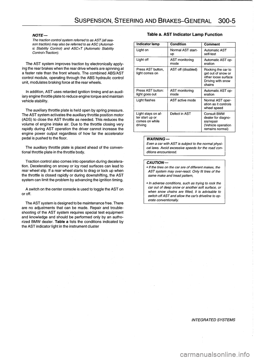
Table
a
lists
theconditions
indicated
by
the
AST
indicator
light
in
the
instrument
cluster
SUSPENSION,
STEERING
AND
BRAKES-GENERAL
300-5
Tablea
.
AST
Indicator
Lamp
Function
Indicator
lamp
1
Condition
1
Comment
Light
on
Normal
AST
start-
Automatic
AST
up
self-test
Light
off
AST
monitoring
Automatic
AST
op-
mode
eration
Press
AST
button,
AST
off
(disabled)
Rocking
the
car
tolight
comes
on
getout
of
snow
or
other
loose
surface
Driving
with
snow
chains
Press
AST
button
:
AST
monitoring
Automatic
AST
op-
light
goes
out
I
mode
eration
Light
flashes
AST
active
mode
I
Normal
AST
oper-
ation
as
it
controls
wheel
speed
Light
stays
on
af-
Defect
in
AST
Consult
BMW
ter
start
up
or
dealer
for
diagno-
comes
on
while
sis/repair
driving
(Vehicle
operation
remains
normal)
WARNING
-
Even
a
car
with
AST
is
subject
to
the
normal
physi-
cal
laws
.
Avoid
excessive
speeds
for
the
road
con-
ditions
encountered
.
CAUTION-
"
If
the
tires
on
the
carare
of
different
makes,
the
AST
system
may
over-react
.
Only
fit
tires
of
the
same
make
and
tread
pattem,
"In
adverse
conditions,
such
as
trying
to
rock
the
car
outof
deep
snow
or
another
soft
surface,
or
when
snow
chainsare
fitted,
it
is
advisable
to
switch
off
AST
and
allow
the
cars
driveline
to
op-
erate
conventionally
.
INTEGRATED
SYSTEMS
Page 254 of 759
300-6
SUSPENSION,
STEERING
AND
BRAKES-GENERAL
BATTE
RY
KL
30
ECM
MAIN
C~
RELAY
KL
15
DSC
SWITCH
LF1
;1~lZZ~
nSLn
l'
z
sJ
WHEEL
RF
c_
.
LR
r_
.
>
RR
ELECTRONIC
BRAKE
LIGHT
SWITCH
SPEED
SENSORS
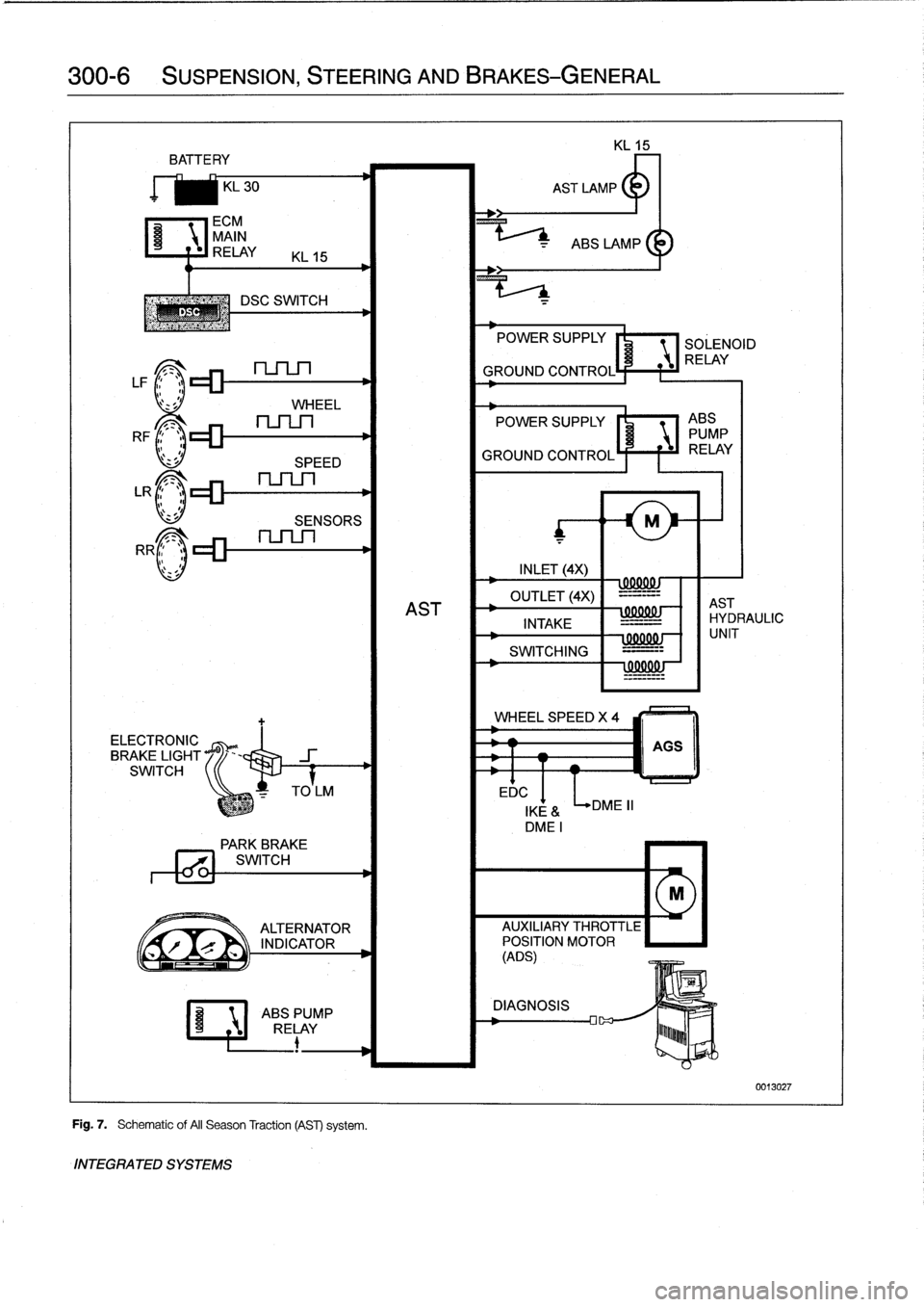
Fig
.
7
.
Schematic
of
AII
Season
Traction
(AST)
system
.
INTEGRATED
SYSTEMS
EDC
POWER
SUPPLY
SOLENOID
RELAY
GROUND
CONTROL
POWER
SUPPLY
I'
1
ABS
PUMP
GROUND
CONTROLÍ
F
f
iJ
RELAY
INLET
(4X)
wxxuw
OUTLET
(4X)
-=-=--
AST
AST
INTAKE
IHYDRAULIC
-
=-
SWITCHING
=---
!
99001
!J
WHEEL
SPEED
X
4
DME
II
000001
-
f
1
UNIT
AGS
IKE
&
DMEI
PARK
BREVE
771
SWITCH
M
ALTERNATOR
AUXILIARY
THROTTLE
r
`
INDICATOR
POSITION
MOTOR
(ADS)
ABSPUMP
DIAGNOSIS
RELAY
lu~~~b
0013027
Page 267 of 759
320
Steering
and
Wheel
Alignment
GENERAL
...
.
.
.
...
.
....
.
.
.
.
.
.
.
.
.
...
.
.
320-1
Outer
tie
rod
end,
replacing
.
...
.
.
.
.
.
.
.
...
.
320-4
Tie
rod,
replacing
.
.
.
.
.
.
.
.......
.
.
.
.
.
...
.
320-5
STEERING
WHEEL
320-1
Steering
wheel,
removing
and
installing
.....
320-1
WHEEL
ALIGNMENT
.
.
.
.........
.
.....
.320-5
POWER
STEERING
SYSTEM
.
.
.
.
.
.
.....
320-2
Front
Toe-in
and
Toe
Difference
Angle
.
.
...
.
320-6
Power
steering
pump,
Rear
Toe-in
.
.
.
.
.
.
.
...
.
................
320-6
removing
and
installing
..
.
.
.
.
.
.
.
.
.
.....
320-2
Wheel
Alignment
Specifications
.....
.
......
320-6
Power
steering
system,
bleeding
and
filling
.
.
320-3
STEERING
GEAR
.
.
.
.
...
.
.
.
.
.
.
.
.
.
.....
320-3
Steering
gear
rack,
removing
and
installing
.
...
.
..
.
..
..
..
.
..
.
320-3
GENERAL
STEERING
WHEEL
This
repair
group
covers
servicing
of
the
mechanical
and
The
BMW
E36
is
equipped
with
an
SRS
airbag
mounted
in
hydraulic
components
of
the
steering
system,
including
wheel
the
steering
wheel
.
Improper
handling
of
the
airbag
could
alignment
information
.
cause
serious
injury
.
The
airbag
is
an
explosivedevice
and
should
be
treated
with
extreme
caution
.
Always
follow
the
air-
The
variable-assist
power
steering
system
consistsof
an
bag
removal
procedure
as
outlined
in
721
Airbag
System
engine-driven
hydraulic
pump,
a
rack-and-pinion
steering
(SRS)
.
gear
assembly
with
an
integral
hydraulic
control
valve,
and
connecting
linkage
to
the
road
wheels
.
WARNING-
"
The
BMW
Supplemental
Restraint
System
(SRS)
At
lowspeeds,
maximum
power
assist
is
provided
to
ease
is
complex
and
special
precautions
must
be
ob-
parking
and
city
driving
.
At
high
speeds,
assist
is
reduced
to
served
when
servicing
.
Serious
injury
may
result
ensure
stability
.
The
power
steering
system
varies
assist
if
system
service
is
attempted
by
persons
unfa-
based
on
engine
speed
.
miliar
with
the
BMW
SRS
and
its
approved
ser-
vice
procedures
.
BMW
specifies
that
all
ING-
inspection
and
service
shouldbe
performed
by
WARN
an
authorized
BMW
dealer
.
"
Do
not
reuse
self-locking
nuts
.
They
are
de-signed
to
beused
only
once
and
may
failif
re-
"
BMW
Supplemental
Restraint
Systems
(SRS)
used
.
Always
replace
them
with
new
locking
nuts
.
are
equipped
with
a
back-up
power
supply
inside
the
SRS
control
module
.
A
10minute
waiting
"
Do
not
ínstall
bolts
and
nuts
coated
with
under-
shouldbe
observed
after
the
battery
cable
has
coating
wax,
as
correct
tightening
torque
cannot
been
disconnected
.
This
will
allow
the
reserve
be
assured
.
Always
clean
the
threads
with
sol-
power
supply
to
discharge
.
vent
before
installation,
or
install
new
parts
.
"
Do
not
attempt
to
weldor
straighten
any
steering
components
.
Always
replace
damaged
parts
.
NOTE-
For
information
on
steering
column-mounted
switches
and
the
ignition
lock,
see
612
Switches
and
Electrical
Accessories
.
STEERING
AND
WHEEL
ALIGNMENT
320-1
Caster
and
Camber
.
.
.
.
.
...........
.
....
320-5
TABLES
a
.
Front
Wheel
Alignment
Specifications
.
...
.......
320-6
b
.
Rear
Wheel
Alignment
Specifications
.
...
.......
320-6
Steering
wheel,
removing
and
installing
1
.
Center
steering
wheel
.
Make
sure
front
wheelsare
pointed
straight
ahead
.
2
.
Disconnect
negative
(-)
cable
from
battery
and
cover
terminal
with
insulating
material
.
CAUTION-
Prior
to
disconnectiog
the
battery,
read
the
battery
disconnection
cautions
given
at
the
front
of
this
manual
on
page
viii
.
STEERING
WHEEL
Page 299 of 759
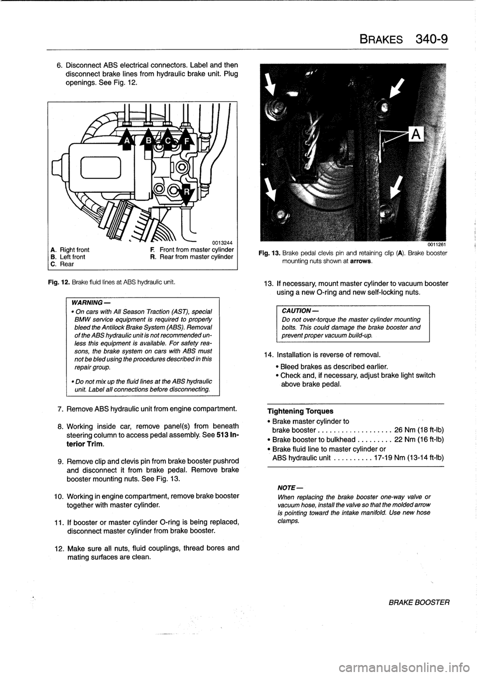
6
.
Disconnect
ABS
electrical
connectors
.
Label
and
then
disconnect
brake
lines
from
hydraulic
brake
unit
.
Plug
openíngs
.
See
Fig
.
12
.
~
~
A
1/
B
'1v
C
~
F
lu
11
-ri
J
.
0013244
A
.
Right
front
F
Front
from
master
cylinder
B
.
Leftfront
R
.
Rear
from
master
cylinder
C
.
Rear
Fig
.
12
.
Brake
fluid
linesat
ABS
hydraulic
unit
.
WARNING
-
"
On
cars
with
All
Season
Traction
(AST),
special
BMW
service
equipment
is
required
to
properly
bleed
the
Antilock
Brake
System
(ABS)
.
Removal
of
the
ABS
hydraulic
unit
is
not
recommended
un-
less
this
equipment
is
available
.
For
safetyrea-
sons,
the
brake
system
on
cars
with
ABS
must
not
be
bled
using
the
procedures
described
inthis
repair
group
.
"
Do
not
mix
up
the
fluid
fines
at
the
ABS
hydraulic
unit
Label
all
connections
before
disconnecting
.
7
.
Remove
ABS
hydraulic
unit
from
engine
compartment
.
8
.
Working
inside
car,
remove
panel(s)
frombeneath
steering
column
to
access
pedal
assembly
.
See513
In-
terior
Trim
.
12
.
Make
sure
al¡
nuts,
fluid
couplings,
thread
bores
and
mating
surfaces
are
clean
.
BRAKES
340-
9
0011261
Fig
.
13
.
Brake
pedal
clevispin
and
retaining
clip
(A)
.
Brake
booster
mounting
nuts
shown
at
arrows
.
13
.
If
necessary,
mount
master
cylinder
to
vacuum
booster
using
a
new
O-ríng
and
newself-locking
nuts
.
CAUTION-
Do
not
over-torque
the
master
cylinder
mounting
bolts
.
This
could
damage
the
brake
booster
and
prevent
proper
vacuum
build-up
.
14
.
Installation
is
reverse
of
Rmoval
.
"
Bleed
brakes
as
described
earlier
.
"
Check
and,
if
necessary,
adjust
brake
light
switch
above
brake
pedal
.
Tightening
Torques
"
Brakemaster
cylinder
to
brake
booster
...........
.
..
..
...
26
Nm
(18
ft-Ib)
"
Brake
booster
to
bulkhead
.
.
..
..
...
22
Nm
(16
ft-Ib)
"
Brake
fluidline
to
master
cylinder
or
ABS
hydraulic
unit
.......
.
..
17-19
Nm
(13-14
ft-lb)
9
.
Remove
clip
and
clevis
pin
from
brake
booster
pushrod
and
disconnect
it
from
brakepedal
.
Remove
brake
booster
mounting
nuts
.
See
Fig
.
13
.
NOTE-
10
.
Working
in
engine
compartment,
remove
brake
booster
When
replacing
the
brake
booster
one-way
valve
or
together
with
master
cylinder
.
vacuum
hose,
install
the
valve
so
that
the
molded
arrow
is
pointing
toward
the
intake
manifold
.
Use
new
hose
11
.
If
booster
or
master
cylinder
O-ring
is
being
replaced,
clamps
.
disconnect
master
cylinder
from
brake
booster
.
BRAKE
BOOSTER
Page 306 of 759
400-
4
BODY-GENERAL
INTERIOR
EQUIPMENT
E36
interiors
have
a
unique
character,
with
a
combínation
of
sporty
features
and
innovative
design
.
Al¡
body
versions
were
made
in
a
wide
choice
of
interior
and
exterior
colors
.
New
colors
with
matching
leather
and/or
fabric
upholstery
were
in-
troduced
for
each
model
year,
including
light-alloy
wheels
in
new
designs
.
Driving
comfort
is
enhanced
by
power
steering,
tilt
steering
wheel
(optional),
height-adjustable
front
seats,
and
electrical-
ly
adjustable
and
heated
rear-view
mirrors
.
Inside
thecar
there
are
reading
lights
at
four
seating
positions
.
Seats
and
Seat
Belts
NOTE-
Theseat
base
usedon
cars
with
pyrotechnic
seatbelt
Anatom¡cal
ly-correct
seats
are
constructed
from
polyure-
tensioners
is
not
interchangeable
with
the
earlier
seat
thane
foam
containing
areas
or
"zones"
of
different
firmness
.
base
.
The
seat
bases
have
steel
springs
for
added
support
and
strength
.
The
power
seats
are
provided
with
conveniently
lo-
Instruments
and
Controls
cated
switches
along
the
outside
edge
of
the
seat
.
Heated
seats
are
an
option
in
all
models
.
See
520
Seats
for
more
de-
Everything
in
the
interior
passenger
compartment
essential
tails
.
to
the
driver
is
logically
grouped
and
easy
to
reach
.
Al¡
instru-
ments
and
controls
havebeen
arranged
ergonomically
and
The
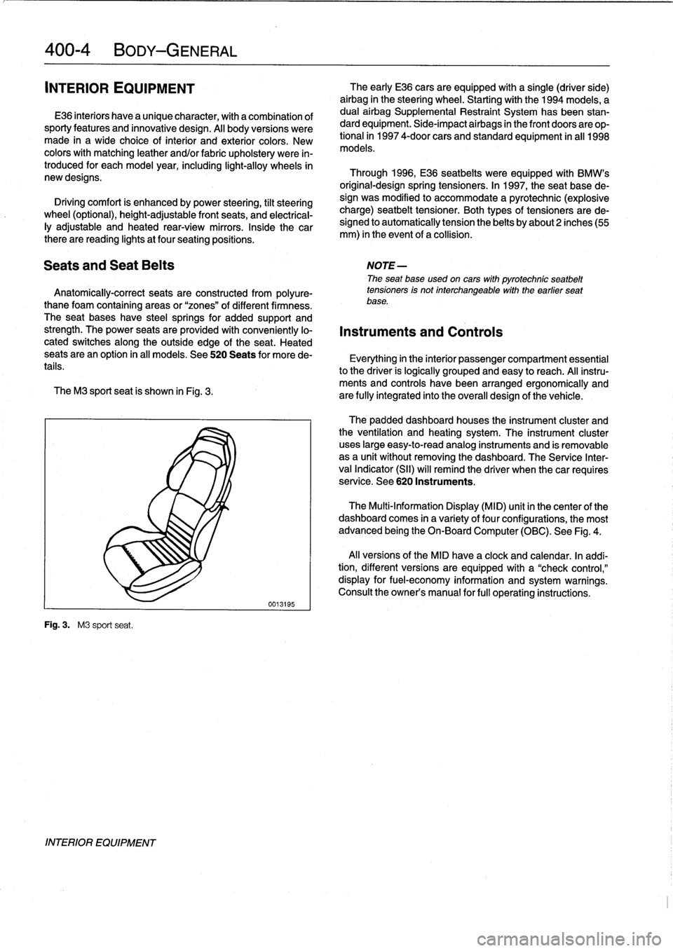
M3
sport
seat
is
shown
in
Fig
.
3
.
are
fully
integrated
into
the
overall
design
of
the
vehicle
.
Fig
.
3
.
M3
sport
seat
.
INTERIOR
EQUIPMENT
0013195
The
early
E36
cars
areequipped
with
a
single
(driver
side)
airbag
in
the
steering
wheel
.
Startingwith
the
1994
models,
a
dual
airbag
Supplemental
Restraint
System
has
been
stan-
dard
equipment
.
Side-impact
airbags
in
the
front
doors
are
op-
tional
in
1997
4-door
cars
and
standard
equipment
in
all
1998
models
.
Through
1996,
E36
seatbelts
were
equipped
with
BMW's
original-designspring
tensioners
.
In
1997,
the
seat
base
de-
sign
was
modified
to
accommodate
a
pyrotechnic
(explosive
charge)
seatbelt
tensioner
.
Both
types
of
tensioners
arede-
signed
to
automatically
tension
the
belts
by
about2
inches(55
mm)
in
the
event
of
a
collision
.
The
padded
dashboard
houses
the
instrument
cluster
and
the
ventilation
and
heating
system
.
The
instrument
cluster
uses
large
easy-to-read
analog
instruments
and
is
removable
as
a
unit
without
removing
the
dashboard
.
The
Service
Inter-
val
Indicator
(SII)
will
remind
the
driver
when
thecar
requires
service
.
See
620
Instruments
.
The
Multi-Information
Display
(MID)
unit
in
thecenter
of
the
dashboard
comes
in
a
variety
of
four
configurations,
the
most
advanced
being
the
On-Board
Computer
(OBC)
.
See
Fig
.
4
.
Al¡
versions
of
the
MID
have
a
clock
and
calendar
.
In
addi-
tion,
different
versions
areequipped
with
a
"check
control,"
display
for
fuel-economy
information
and
system
warnings
.
Consult
the
owner's
manual
for
fui¡
operating
instructions
.