jack stand BMW 328i 1995 E36 Workshop Manual
[x] Cancel search | Manufacturer: BMW, Model Year: 1995, Model line: 328i, Model: BMW 328i 1995 E36Pages: 759
Page 7 of 759
Please
read
these
warnings
and
cautions
before
proceeding
with
maintenance
and
repair
work
.
WARNING-
"
Friction
materials
(such
as
brake
pads
or
shorts
or
clutchdiscs)
contain
asbestos
fibers
or
other
friction
materials
.
Do
notcreate
"
See
also
Cautionson
page
viü
dustby
grinding,
sanding,
orby
cleaning
with
compressed
air
.
"
Some
repairs
may
be
beyond
your
capability
.
If
you
lack
the
Avoid
breathing
dust
.
Breathing
any
friction
material
dust
can
lead
skills,
tools
and
equipment,
or
a
suitable
workplace
for
any
proce-
to
serious
diseases
and
may
result
in
death
.
duredescribed
in
this
manual,
we
suggestyou
leave
such
repairs
"
Batteries
give
off
explosive
hydrogen
gas
during
charging
.
to
an
authorized
BMW
dealer
service
department
or
other
quali-
Keep
sparks,
lighted
matches
and
open
flame
away
from
the
top
fied
shop
.
of
the
battery
If
hydrogen
gas
escaping
from
the
cap
vents
is
"Do
not
re-use
any
fasteners
that
are
worn
or
deformed
in
normal
ignited,
it
will
ignite
gas
trapped
in
the
cells
and
cause
the
battery
use
.
Many
fasteners
are
designed
to
be
used
only
once
and
to
explode
.
become
unreliable
and
may
fail
when
used
a
second
time
.
This
"
Connect
and
disconnect
battery
cables,
jumper
cablesora
bat-
includes,
but
is
not
limited
to,
nuts,
bolts,
washers,
self-locking
nuts
or
bolts,
circlips
and
cotterpins
.
Always
replace
these
fasteners
with
new
parts
.
"Do
not
quick-charge
the
battery
(for
boost
starting)
for
longer
"
Never
work
under
a
lifted
car
unless
it
is
solidly
supportedon
than
one
minute
.
Wait
at
least
one
minute
before
boosting
the
bat-
stands
designed
for
the
purpose
.
Do
not
support
a
car
on
cinder
tery
a
second
time
.
blocks,
hollow
tiles
or
other
props
that
may
crumble
under
contin-
uous
load
.
Never
work
under
acar
that
is
supported
solely
by
a
"Do
not
allow
battery
charging
voltage
to
exceed
16
.5
volts
.
If
the
jack
.
Never
work
under
thecar
while
the
engine
is
running
.
battery
beginsproducing
gas
or
boiling
violently,
reduce
the
charg-
ing
rate
.
Boosting
a
sulfated
battery
at
a
high
charging
rate
can
"
If
you
are
going
to
work
under
acar
on
the
ground,
make
sure
cause
an
explosion
.
that
the
ground
is
level
.
Block
the
wheels
to
keep
the
carfrom
roll-
ing
.
Disconnect
the
battery
negative
(-)
terminal
(ground
strap)to
"
The
air-conditioning
system
is
filled
with
chemical
refrigerant,
prevent
others
from
starting
thecar
while
youare
under
it
.
which
is
hazardous
.
TheA/C
system
should
be
servicedonly
by
trained
technicians
using
approved
refrigerant
recovery/recycling
"
Never
run
the
engine
unless
the
work
area
is
well
ventilated
.
equipment,
trained
in
related
safetyprecautions,
and
familiar
with
Carbon
monoxide
kills
.
regulations
governing
the
discharging
and
disposal
of
automotive
"
Finger
rings,
bracelets
and
other
jewelry
shouldbe
removed
so
chemical
refrigerants
.
tery
charger
only
with
the
ignition
switched
off,
to
prevent
sparks
.
Do
not
disconnect
the
battery
while
the
engine
is
running
.
that
theycannot
cause
electrical
shorts,
get
caught
in
running
"
Do
not
expose
any
partof
the
A/Csystem
to
high
temperatures
machinery,
or
be
crushed
by
heavy
parts
.
suchas
open
flame
.
Excessiveheat
will
increase
system
pressure
"
Tie
long
hair
behind
your
head
.
Do
not
wear
a
necktie,
a
scarf,
and
may
cause
the
system
to
burst
.
loose
clothing,
or
a
necklace
when
you
work
near
machine
tools
or
"
Some
aerosol
tire
inflators
are
highly
flammable
.
Be
extremely
running
engines
.
If
your
hair,
clothing,
or
jewelry
were
to
get
caught
cautious
when
repairing
a
tire
that
may
havebeen
inflated
using
in
the
machinery,
severe
injury
could
result
.
an
aerosol
tire
inflator
.
Keep
sparks,
open
flame
or
other
sources
"
Do
not
attempt
to
work
onyourcar
if
you
do
not
feel
well
.
You
of
ignition
away
from
the
tire
repair
area
.
Inflate
and
deflate
the
tire
increase
the
danger
of
injury
toyourself
and
others
if
you
are
tired,
at
least
four
times
before
breaking
the
bead
from
therim
.
Com-
upset
or
have
takenmedication
or
any
other
substance
that
may
Pletely
remove
the
tire
from
the
rim
beforeattempting
any
repair
.
keep
you
from
being
fully
alert
.
"
Illuminate
your
work
areaadequately
but
safety
.
Use
a
portable
safety
light
for
working
inside
or
under
thecar
.
Make
surethe
bulb
is
enclosedbya
wire
cage
.
The
hot
filament
of
an
accidentally
bro-
ken
bulb
can
ignite
spilled
fuel
or
oil
.
"
Catch
draining
fuel,
oil,
orbrake
fluid
in
suitable
containers
.
Do
not
use
food
or
beverage
containers
that
mightmislead
someone
into
drínking
from
them
.
Store
flammable
fluids
away
from
fire
haz-
ards
.
Wipe
up
spills
at
once,
but
do
not
store
the
oily
rags,
which
can
ignite
and
burn
spontaneously
.
"
Always
observe
good
workshop
practices
.
Wear
goggles
when
youoperate
machine
tools
or
work
with
battery
acid
.
Gloves
or
other
protectioeclothing
should
be
worn
whenever
thejob
requires
working
with
harmful
substances
.
"
Greases,
lubricants
and
other
automotive
chemicals
contain
toxic
substances,
many
of
which
are
absorbed
directly
through
the
skin
.
Read
the
manufacturer's
instructions
and
warnings
carefully
.
Use
hand
andeye
protection
.
Avoid
direct
skin
contact
"
Cars
covered
by
this
manual
are
equipped
with
a
supplemental
restraint
system
(SRS),
that
automatically
deploys
an
airbag(s)
in
theevent
of
a
frontal
ímpact
.
The
airbag(s)
is
inflated
byan
explo-
sive
device
.
Handled
improperly
or
without
adequate
safeguards,
can
be
accidently
activated
and
cause
serious
injury
.
"
The
ignition
system
produces
high
voltages
that
can
be
fatal
.
Avoid
contact
with
exposed
terminals
and
use
extreme
care
when
working
ona
car
with
the
engine
running
or
the
ígnition
switched
on
.
"
Place
jack
stands
only
at
locations
specified
bymanufacturer
.
The
vehicle
lifting
jacksupplied
with
the
vehicle
is
intended
for
tire
changes
only
.
A
heavy
duty
floor
jack
shouldbe
used
to
lift
vehicle
before
installing
jack
stands
.
See
010
Fundamentals
for
theDo-
.
it-Yourself
Owner
.
"
Battery
acid
(electrolyte)
can
cause
severeburns
.
Flush
contact
area
with
water,
seek
medical
attention
.
"
Aerosolcleaners
and
solvents
may
contain
hazardous
ordeadly
vapors
and
are
highly
flammable
.
Use
only
in
a
wellventilated
area
.
Do
not
use
on
hot
surfaces
(engines,
brakes,
etc
.)
.
"
Disconnect
the
battery
negative
(-)
terminal
(Ground
strap)
"
Do
not
remove
coolant
reservoir
or
radiator
cap
with
theengine
whenever
you
work
on
the
fuel
system
orthe
electrical
system
.
Do
hot
.
Danger
of
bums
and
engine
damage
.
not
smoke
or
work
near
heaters
or
other
fire
hazards
.
Keep
an
approved
fire
extinguisher
handy
.
continued
on
next
page
vii
Page 9 of 759
GENERAL
FUNDAMENTALS
FORTHE
DO-IT
YOURSELF
OWNER
010-1
010
Fundamentals
for
the
Do-lt-Yourself
Owner
GENERAL
.......
.
.
.
......
.
.........
.
.
.010-1
TOOLS
.
.
...
.
............
.
............
010-8
Basic
Tool
Requirements
......
.
.
.
.
.
.
.
.
.
.
010-8
HOW
TO
USE
THIS
MANUAL
.
...
.
...
.
.
.
010-2
JackStands
.
.
.
.
.
.
.
.
.
.......
.
.
.
.
...
.
.
010-9
Warnings,
Cautions
and
Notes
.........
.
.
.
010-2
Oil
Change
Equipment
.
....
.
......
.
...
.
.
010-9
GETTING
STARTED
.
.......
.
.
.
.
.
......
.010-2
Torque
Wrench
....
.
.
.
....
.
..
.
.
.
.
.
...
.
010-10
Feeler
Gauges
.
...
.
.
.
.......
.
.
.
.
.
.
.
.
.
010-10
Safety
....
.
.....
.....
.
.
.
.
.
...
.
.
.
.
.
.
.
010-2
Digital
Multimeter
.
.
.
.
.
.....
.
.
.
.
.
.
.
.
.
.
.
010-10
Lífting
the
Car
...........
.
.
.
.
.
.
.
.
.
...
.
.
.
010-3
gMW
Special
Tools
...
.
....
..
.....
.
...
.
010-11
Raising
car
safely
...
..
...
.
...
.
.....
.
...
010-3
Working
under
car
safely
...
..
....
.
.....
.
...
010-4
EMERGENCIES
.
.
.
.
.
.
.....
.
.
.
.
.
.
.
...
.
010-11
ADVICE
FOR
THE
BEGINNER
.......
.
.
.
010-4
Changing
a
Tire
.
.
.
.
.
.
....
..
.
.
.
.
.
.
.
.
.
.010-11
Car
Will
Not
Start
....
.
....
.
.
.
........
.010-11
Planning
Ahead
....
.
...........
.
....
.
.
.
010-4
Jump
Starting
Car
..
.
.
.
....
.
...........
010-12
Cleanliness
.
.
.
.
.
.
.
..
....
.
.
.
.
.
.
.
.
.
.
.
.
.
.
.
010-4
Overheating
.
.....
.
.
.
.........
.
.
.
...
.
010-12
Non-reusable
Fasteners
...
.
.
.
.
.
.
.
.
.
.
.
.
.
.
.
010-5
Low
Oil
Pressure
...
...
.
.
...
.
.
.
..
...
....
010-13
Tightening
Fasteners
.....
.
.
.
...
.
.
.
.
.
.
.
.
.
010-5
Brake
Fluid
Level
.
.
.....
.
.
.
.
.
...
.
.....
010-13
Gaskets
and
Seals
.......
.
.
.
...
.
.....
.
.
.
010-5
Check
Engine
Warning
Light
.
.
.
...
.
.....
010-13
Electrical
Testing
.
.
.
.
.
.
.
.
.
.
.
.
.
.
.
.
.
...
.
.
.
010-6
pim
Lights
.....
.
..
.
.
.
....
.
.
.
.........
010-13Wire
Repairs
.
.
.
.
.
.
.
.
.
.
...
.
.
.
.
.
.
.
......
010-6
Towíng
.
.
...
.
.
.
.
.
.
.
.
.
.
.
...
.
.
.
.
.
...
.
.010-13
BUYINGPARTS
.
.
.
.....
.
.
.
...
.
.
.
...
.
.
.
010-6
Spare
Parts
Kit
.
.
.
.
.
.
.......
.
.
.
.
.
.....
010-14
Genuine
BMW
Parts
.
.
.
.
.
.
.
.
.
.
.
.
.
.
......
010-6
Non-returnable
Parts
.
.
.
.
.
.
.
.
.
.
.
.
.
.
......
010-7
TABLES
Information
You
Need
to
Know
.
.
.
.
.
.
......
010-7
a
.
General
Bolt
Tightening
Torques
SERVICE
.
.
.
.
.
.
.
.
.
.
.
.
.......
.
..........
010-7
Although
the
BMW
is
a
sophisticated
and
complex
machine,
basic
maintenance
can
be
accomplished
byan
interested
own-
er
with
mechanical
skills
and
the
right
information
.
Most
of
the
preventive
maintenance
that
is
required
in
the
lifetime
of
theav-
erage
BMW
is
weil
within
the
capabilitiesof
the
do-it-yourseifer
.
WARNING
-
Do
not
use
this
manual
unless
you
are
familiar
with
basicautomotive
repair
procedures
and
sale
work-
shop
practices
.
This
manual
illustrates
the
work-
shop
procedures
required
for
most
service
work
;it
is
not
a
substitute
for
full
and
up-to-date
information
from
the
vehicle
manufacturer
or
for
proper
training
asan
automotive
technician
.
Note
that
it
is
not
pos-
sible
for
us
to
anticipate
al¡
of
the
ways
orconditions
underwhich
vehicles
may
be
serviced
or
to
provide
cautions
as
to
all
of
the
possible
hazards
that
may
result
'
in
Nm
(max
.
permissible)
.
..
.
...
............
.
010-5
WARNING
-
Your
common
sense
and
good
judgment
are
crucial
tosale
and
successful
service
work
.
Read
proce-
dures
through
before
starting
them
.
Thinkabout
whether
the
condition
ofyour
car,
your
leve¡
of
me-
chanical
skill,
or
your
leve¡
of
reading
comprehen-
sion
might
result
in
orcontribute
in
some
way
to
an
occurrence
that
might
cause
you
injury
damage
your
car,
or
result
in
an
unsafe
repair
.
lf
you
havedoubts
for
these
or
other
reasonsaboutyour
abilíty
to
perform
sale
repair
work
onyour
car,
have
the
work
done
at
an
authorized
BMW
dealer
or
other
qualified
shop
.
This
section
of
the
manual
is
intended
to
helpthe
beginner
get
started
.
To
begin
with
there
is
a
discussion
on
How
To
Use
This
Manual
.
Tips
on
mechanicas
skills
and
workshop
practic-
es
that
can
help
the
beginner
do
a
faster
and
more
thorough
job
can
be
foundunderGettingStarted
.
The
basic
tools
needed
to
do
most
of
the
procedures
in
this
manual
are
foundunder
Tools
.
The
section
ends
with
a
quick
reference
guide
to
Emer-
gencies,
including
basictroubleshooting
and
information
on
how
to
gauge
the
seriousness
of
a
problem
.
GENERAL
Page 11 of 759
WARNING
-
"
Never
work
under
a
lifted
car
unless
it
is
solidly
supported
on
jack
stands
that
are
intended
for
that
purpose
.
Do
not
support
a
car
on
cinder
blocks,
bricks,
or
other
objects
that
may
shift
orcrumble
under
continuous
load
.
Never
work
un-
dera
car
that
is
supported
only
by
the
lifting
jack
.
"
Fuel
is
highly
flammable
.
When
working
around
fuel,
do
not
smoke
or
worknear
heaters
or
other
fire
hazards
.
Keepan
approved
fire
extinguisher
handy
.
"
llluminate
the
work
area
adequately
and
safely
.
Use
a
portable
safety
light
for
working
inside
or
under
thecar
.
A
fluorescent
type
lightis
best
be-
cause
it
gives
off
less
heat
.
If
using
a
light
with
anormal
incandescent
butb,
use
rough
service
bulbs
to
avoid
breakage
.
The
hot
filamentof
an
accidentallybroken
bulb
can
ignite
spilled
fuel
or
oil
"
Keep
sparks,
lighted
matches,
and
any
open
llame
away
from
thetop
of
the
battery
.
Hydrogen
gas
emitted
by
the
battery
is
highly
flammable
.
Any
nearby
source
of
ignition
may
cause
the
battery
to
explode
.
"
Never
¡ay
tools
or
parts
in
the
engine
compart-
ment
or
on
top
of
the
battery
.
They
may
fall
into
confined
spaces
and
be
difficult
toretrieve,
be-
come
caught
in
beits
or
other
rotating
parts
when
the
engine
is
started,
or
cause
electrical
shorts
anddamage
to
the
electrical
system
.
"
The
fuel
system
is
designed
to
retain
pressure
even
when
the
ignition
is
off
.
When
working
with
the
fuel
system,
loosen
the
fuel
fines
slowly
to
al-
low
the
residual
pressure
to
dissipate
gradually
.
Take
precautions
to
avoid
spraying
fuel
.
Lifting
the
Car
FUNDAMENTALS
FOR
THE
DO-ITYOURSELF
OWNER
010-
3
For
those
repairs
that
require
raising
the
car,
theproper
jack-
ing
points
should
beused
to
raise
thecar
safely
and
avoid
dam-
age
.
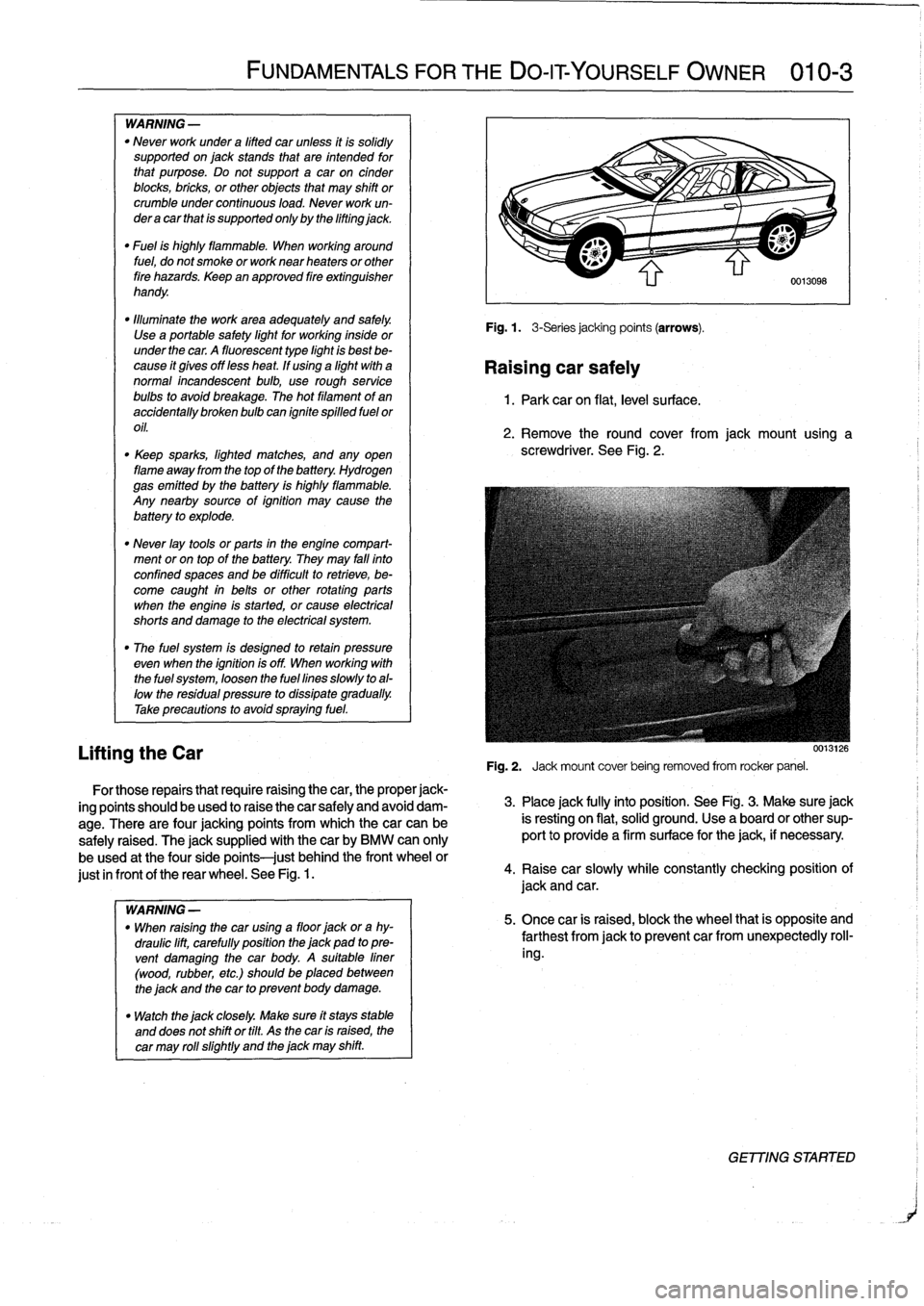
There
are
four
jacking
points
from
which
thecar
can
be
safely
raised
.
The
jacksupplied
with
thecar
by
BMW
can
only
be
used
at
the
fourside
points
just
behindthe
front
wheel
or
just
in
frontof
the
rear
wheel
.
See
Fig
.
1.
WARNING
-
"
When
raising
the
car
using
a
floor
jack
ora
hy-
draulic
lift,
carefully
position
the
jack
pad
topre-
vent
damaging
the
car
body
.
A
suitable
liner
(wood,
rubber,
etc
.)
should
be
placed
between
the
jack
and
the
car
to
prevent
body
damage
.
"
Watch
the
jack
closely
.
Make
sure
ft
stays
stable
and
does
not
shift
or
tilt
.
As
the
car
is
raised,
the
car
may
rol¡
slightly
and
the
jack
may
shift
.
Fig
.
1
.
3-Seriesjacking
points
(arrows)
.
Raising
car
safely
1
.
Park
car
on
flat,
leve¡
su
rface
.
2
.
Remove
the
round
cover
from
jack
mount
using
a
screwdriver
.
See
Fig
.
2
.
0013126
Fig
.
2
.
Jack
mount
cover
being
removed
from
rocker
panel
.
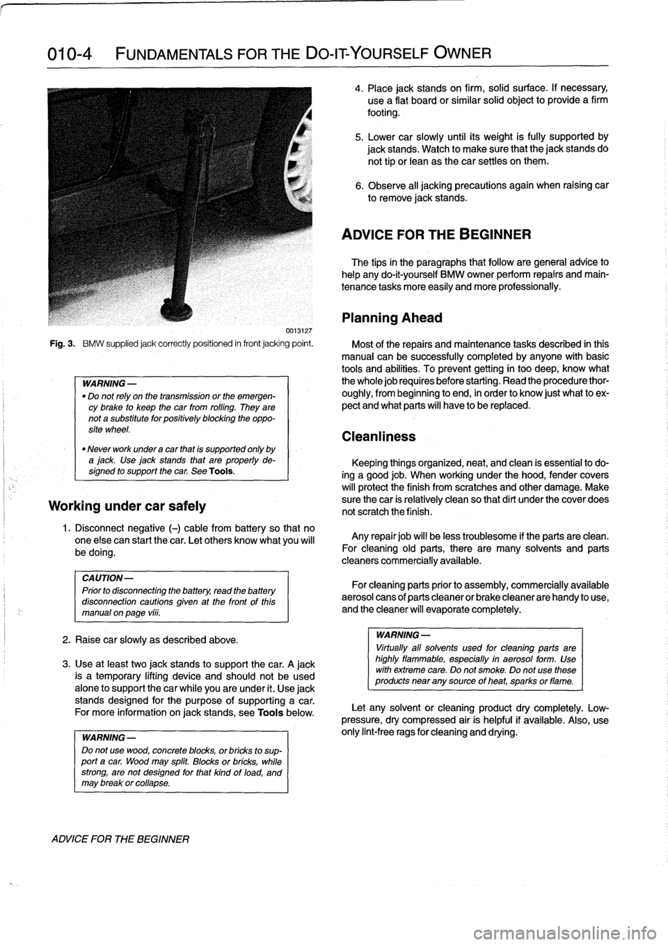
3
.
Place
jack
fully
into
position
.
See
Fig
.
3
.
Make
sure
jack
is
resting
on
flat,
solid
ground
.
Use
a
board
or
other
sup-
port
to
provide
a
firm
surface
for
the
jack,
if
necessary
.
4
.
Raisecar
slowly
while
constantly
checking
position
of
jack
and
car
.
5
.
Once
car
is
raised,
block
the
wheel
that
is
opposite
and
farthest
from
jackto
prevent
car
fromunexpectedly
roll-
ing
.
GET77NG
STARTER
Page 12 of 759
010-
4
FUNDAMENTALS
FOR
THE
DO-ITYOURSELF
OWNER
Fig
.
3
.
BMW
supplied
jack
correctly
positioned
in
front
jacking
point
.
Most
of
the
repairs
and
maintenance
tasks
described
in
this
manual
can
be
successfully
completedby
anyone
with
basic
tools
and
abilities
.
To
prevent
getting
in
too
deep,
know
what
WARNING-
the
wholejob
requires
before
starting
.
Read
the
procedure
thor-
"
Do
not
rely
on
thetransmission
or
the
emergen-
oughly,
from
beginning
to
end,
in
order
to
know
just
what
to
ex
cybrake
to
keep
thecar
from
rolling
.
They
are
pect
and
what
parts
will
have
to
be
replaced
.
nota
substitute
for
positively
blocking
the
oppo-
site
wheel
.
"
Never
work
undera
car
that
is
supported
only
by
ajack
Use
jack
stands
that
are
properly
de-
signed
to
support
the
car
.
See
Tools
.
Working
under
car
safely
1
.
Disconnect
negative
(-)
cable
from
battery
so
that
no
one
else
can
start
thecar
.
Let
others
know
what
you
will
be
doing
.
CAUTION-
Prior
to
disconnecting
the
battery
read
the
battery
disconnection
cautions
given
at
the
front
of
this
manual
on
page
vüi
.
2
.
Raisecar
slowly
as
described
above
.
3
.
Use
at
least
two
jack
stands
to
support
thecar
.
A
jack
is
atemporary
lifting
device
and
should
not
be
used
alone
to
support
the
car
while
you
are
under
it
.
Use
jack
stands
designed
for
the
purpose
of
supporting
a
car
.
For
more
information
on
jack
stands,
see
Toolsbelow
.
WARNING
-
Do
notusewood,
concrete
blocks,
orbricks
to
sup-
port
acar
.
Woodmay
split
.
Blocks
or
bricks,
while
strong,
are
not
designed
for
that
kind
of
load,
and
may
brakkor
collapse
.
ADVICE
FOR
THE
BEGINNER
4
.
Place
jack
stands
on
firm,
solid
surface
.
If
necessary,
use
a
flat
board
or
similar
solid
object
to
provide
a
firm
footing
.
5
.
Lower
car
slowly
until
its
weight
is
fully
supportedby
jack
stands
.
Watch
to
make
sure
that
the
jack
stands
do
not
tip
orlean
as
thecar
settles
on
them
.
6
.
Observe
all
jacking
precautions
again
when
raising
car
to
remove
jack
stands
.
ADVICE
FORTHE
BEGINNER
The
tips
in
the
paragraphs
that
follow
are
general
advice
to
help
any
do-it-yourself
BMW
owner
perform
repairs
and
main-
tenance
tasks
more
easily
and
more
professionally
.
Planning
Ahead
Cleanliness
Keeping
things
organized,
neat,
and
clean
is
essential
to
do-
ing
a
good
job
.
When
working
under
the
hood,
fender
covers
will
protect
the
finish
from
scratches
and
other
damage
.
Make
sure
the
car
is
relatively
clean
so
thatdi
rt
under
the
cover
does
not
scratch
the
finish
.
Any
repair
job
will
be
less
troublesome
if
the
parts
are
clean
.
For
cleaning
old
parts,
there
are
many
solvents
and
parts
cleaners
commercially
available
.
For
cleaning
parts
priorto
assembly,
commercially
available
aerosol
cans
of
parts
cleaner
or
brake
cleaner
are
handy
to
use,
and
the
cleaner
will
evaporate
completely
.
WARNING
-
Virtually
all
solvents
used
for
cleaning
parts
are
highly
flammable,
especially
in
aerosol
form
.
Use
wíth
extreme
care
.
Do
not
smoke
.
Do
not
use
these
products
near
any
source
of
heat,
sparksor
flame
.
Let
any
solvent
orcleaning
product
dry
completely
.
Low-
pressure,
dry
compressed
air
is
helpful
if
available
.
Also,
use
only
lint-free
rags
for
cleaning
and
drying
.
Page 17 of 759
Solt
Diameter
and
Wrench
Size
"
M5
.
...
............
....
......
.
.......
8
mm
"
M6
.
.
..............
.
.
...
...........
.10
mm
"
M8
.
.
..............
.
.
..
.....
12mmor13mm
"
M10
..
.............
.
.
...
...........
.17
mm
"
M12
...
...........
..
.
..
............
.19
mm
"
M14
.
..:
.
.........
..
.
..
.............
22
mm
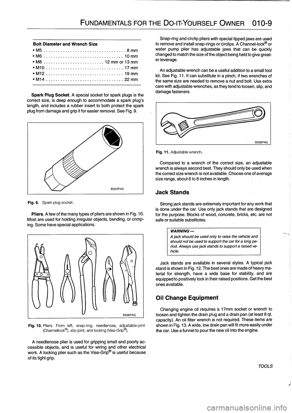
Spark
Plug
Socket
.
A
special
socket
for
spark
plugs
is
the
correct
size,
is
deep
enough
to
accommodate
a
spark
plug's
length,
and
includes
a
rubber
insertto
both
protect
the
spark
plug
from
damage
and
grip
it
for
easier
removal
.
See
Fig
.
9
.
Fig
.
9
.
Spark
plug
socket
.
FUNDAMENTALS
FOR
THEDO-ITYOURSELF
OWNER
010-
9
B003FNG
Pliers
.
A
few
of
the
many
types
ofpliers
are
shown
in
Fig
.
10
.
Mostare
used
for
holding
irregularobjects,
bending,or
crimp-
ing
.
Some
have
special
applications
.
A
needlenose
plier
is
used
for
gripping
small
and
poorly
ac-
cessible
objects,
and
is
useful
for
wiring
and
other
electrical
work
.
A
locking
plier
suchas
theVise-Grip
®
is
useful
because
of
its
tightgrip
.
Snap-ring
and
circlip
pliers
withspecial
tipped
jacas
areused
lo
remove
and
install
snap-ringsor
circlips
.
A
Channel-lock®
or
water
pump
plier
has
adjustable
jacas
that
can
be
quickly
changed
to
match
the
size
of
the
object
being
held
to
give
great-
erleverage
.
An
adjustable
wrench
canbea
useful
addition
to
a
small
tool
kit
.
See
Fig
.
11
.
It
can
substitute
in
a
pinch,
if
two
wrenches
of
the
same
size
are
needed
lo
remove
a
nut
and
bolt
.
Use
extra
care
with
adjustable
wrenches,
as
they
tend
to
loosen,
slip,
and
damage
fasteners
.
Fig
.
11
.
Adjustable
wrench
.
B008FNG
Compared
to
a
wrench
of
the
correct
size,
an
adjustable
wrench
is
always
second
best
.
They
shouldonly
beused
when
the
correct
size
wrench
is
not
available
.
Choose
one
of
average
size
range,
about
6
to
8
inches
in
length
.
Jack
Stands
Strong
jack
stands
are
extremely
important
for
any
work
that
is
done
under
thecar
.
Use
onlyjack
stands
that
are
designed
for
the
purpose
.
Blocks
of
wood,
concrete,
bricks,
etc
.
arenot
safeor
suitable
substitutes
.
WARNING
-
A
jack
should
be
used
only
to
raise
the
vehicle
and
shouldnot
beused
to
support
the
car
for
a
long
pe-
riod
.
Always
use
jack
stands
to
support
a
raised
ve-
hicle
.
Jack
standsare
available
1n
severa¡
styles
.
A
typical
jack
stand
is
shown
in
Fig
.
12
.
The
best
ones
are
made
of
heavy
ma-
terial
for
strength,
have
a
wide
base
for
stability,
and
are
equipped
lo
positively
lock
in
their
raised
positions
.
Get
the
best
ones
available
.
Oil
Change
Equipment
Changing
engine
oil
requires
a
17mm
socket
or
wrench
to
BOO6FNG-
loosen
and
tighten
the
drain
plug
and
a
drain
pan
(at
least
8
qt
.
capacity)
.
An
oil
filter
wrench
is
not
required
.
These
items
are
Fig
.
10
.
Pliers
.
From
left,
snap-ring,
needlenose,
adjustable-joint
shown
in
Fig
.
13
.
A
wide,
loca
drain
pan
wíll
fit
more
easily
under
(Channellock©),
slip-joint,
and
locking(Vise-Grip®)
.
the
car
.
Use
a
funnel
lo
pour
the
new
oil
into
theengine
.
TOOLS
Page 18 of 759
010-10
FUNDAMENTALS
FOR
THE
DO-IT
YOURSELF
OWNER
TOOLS
Torque
Wrench
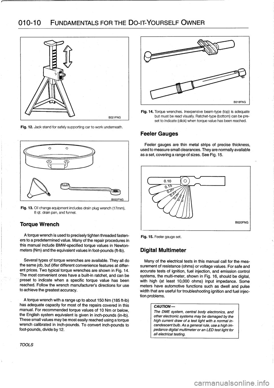
B021FNG
Fig
.
12
.
Jack
stand
for
safely
supporting
car
to
work
underneath
.
B022FNG
Fig
.
13
.
Oil
change
equipment
includesdrainplug
wrench
(17mm),
8
qt
.
drain
pan,
and
funnel
.
A
torque
wrench
is
used
to
precisely
tighten
threaded
fasten-
Fig
.
15
.
Feeler
gauge
set
.
ers
to
a
predetermined
value
.
Many
of
the
repair
procedures
in
this
manual
include
BMW-specified
torquevalues
in
Newton-
meters
(Nm)
and
the
equivalent
values
in
foot-pounds
(ft-Ib)
.
Digital
Multimeter
A
torque
wrench
with
a
range
up
to
about
150
Nm
(185
ft-lb)
has
adequate
capacity
for
most
of
the
repairs
covered
in
this
manual
.
For
recommended
torque
values
of
10
Nm
or
below,the
English
system
equivalent
is
given
in
inch-pounds
(in-lb)
.
These
small
values
may
be
most
easily
reached
using
a
torque
wrench
calibrated
in
inch-pounds
.
To
convert
inch-pounds
to
foot-pounds,
divide
by12
.
Fig
.
14
.
Torque
wrenches
.
Inexpensive
beam-type
(top)
is
adequate
but
must
be
read
visually
.
Ratchet-type
(bottom)
can
be
pre-
set
to
índicate
(click)
when
torquevalue
has
been
reached
.
Feeler
Gauges
B018FNG
Feeler
gauges
are
thin
metal
strips
of
precise
thickness,
used
to
measure
small
clearances
.
They
are
normally
available
as
a
set,
covering
a
range
of
sizes
.
See
Fig
.
15
.
Several
types
of
torque
wrenches
are
available
.
They
al¡
do
Many
of
the
electrical
tests
in
Chis
manual
cal¡
for
the
mea-
the
same
job,
bu¡
óffer
different
convenience
features
at
differ-
surement
of
resistance
(ohms)
or
voltage
values
.
For
safe
and
ent
prices
.
Two
typical
torque
wrenches
are
shown
in
Fig
.
14
.
accurate
tests
of
ignition,
fuel
injection,
and
emission
control
The
most
convenient
ones
have
a
built-in
ratchet,
and
can
be
systems,
the
multi-meter,
shown
in
Fig
.
16,
should
be
digital,
preset
to
indicate
when
a
specific
torque
value
has
been
with
high
(at
least
10,000
ohms)
input
impedance
.
Some
reached
.
Followthe
wrench
manufacturer's
directions
for
use
meters
have
automotive
functions
suchas
dweil
and
pulse
to
achieve
the
greatest
accuracy
.
width
that
are
useful
fortroubleshooting
ignition
and
fuel
injec-
tion
problems
.
CAUTION-
The
DME
system,
central
body
electronics,
and
other
electronic
systems
may
be
damaged
by
the
high
current
draw
of
a
test
fight
with
a
normal
in-
candescent
bulb
.
As
a
general
rule,
usea
high
ím-
pedance
digital
multimeter
or
an
LED
test
fightforall
electrfcal
testfng
.
B020FNG
Page 19 of 759
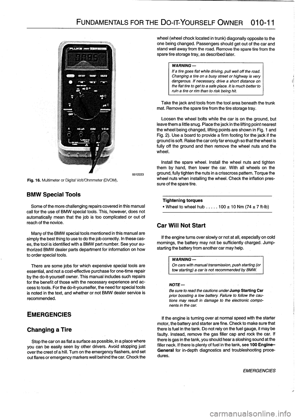
Fig
.
16
.
Multimeter
or
Digital
Volt/Ohmmeter
(DVOM)
.
BMW
Special
Tools
FUNDAMENTALS
FOR
THE
DO-ITYOURSELF
OWNER
010-11
0012223
Some
of
the
more
challenging
repairs
covered
in
this
manual
cal¡
for
the
use
of
BMW
special
tools
.
This,
however,
does
not
automatically
mean
that
thejob
is
too
complicated
or
out
of
reach
of
thenovice
.
Many
of
the
BMW
special
tools
mentioned
in
this
manual
are
simplythe
best
thing
to
use
to
do
thejob
correctly
.
In
these
cas-
es,
the
tool
is
identified
with
a
BMW
part
number
.
See
your
au-
thorized
BMW
dealer
parts
department
for
information
on
how
to
order
special
tools
.
There
are
some
jobs
for
which
expensive
special
tools
are
essential,
and
not
a
cost-effective
purchase
for
one-time
repair
by
the
do-it-yourself
owner
.
This
manual
includes
such
repairs
for
the
benefit
of
these
with
the
necessary
experience
and
ac-
cess
to
tools
.
For
the
do-it-yourselfer,
the
need
for
special
tools
is
noted
in
the
text,
and
whether
or
not
BMW
dealer
service
is
recommended
.
EMERGENCIES
Changing
a
Tire
Stop
thecar
onas
flat
a
surface
as
possible,
in
a
place
where
you
canbe
easily
seen
by
other
drivers
.
Avoid
stopping
just
over
the
crest
of
a
hill
.
Turnon
the
emergency
flashers,
and
set
out
(lares
or
emergency
markers
well
behindthecar
.
Chock
the
wheel
(wheel
chock
located
in
trunk)
diagonally
opposite
to
the
one
being
changed
.
Passengers
shouldgetout
of
thecar
and
stand
well
away
from
the
road
.
Remove
the
spare
tire
from
the
spare
tire
storage
tray,
as
described
later
.
WARNING
-
If
a
tire
goes
fíat
while
drtving,
pull
well
off
the
road
.
Changing
a
tire
ona
busy
street
or
highway
is
very
dangerous
.
If
necessary,
drive
a
short
distance
on
the
fíat
tire
to
get
to
a
sale
place
.
tt
is
much
better
to
ruin
a
tire
or
rim
than
to
risk
being
hit
.
Take
the
jack
and
tools
from
the
tool
area
beneath
the
trunk
mat
.
Remove
the
spare
tire
from
the
tire
storage
tray
.
Loosen
the
wheel
bolts
while
the
car
is
on
the
ground,
but
leave
them
a
little
snug
.
Placethe
jack
in
the
lifting
point
nearest
the
wheel
beingchanged,
lifting
points
are
shown
in
Fig
.
1
and
Fig
.
2)
.
Use
a
board
to
provide
a
firm
footing
for
the
jack
if
the
ground
is
soft
.
Raise
the
car
only
lar
enough
so
that
the
wheel
is
fully
off
the
ground
and
then
remove
the
wheel
nuts
and
the
wheel
.
Insta¡¡
the
spare
wheel
.
Install
the
wheel
nuts
and
tighten
them
by
hand,
then
lower
the
car
.
With
all
wheelson
the
ground,
fully
tighten
the
nuts
in
a
crisscross
pattern
.
Torque
the
wheel
nuts
when
installing
the
wheel
.
Check
the
inflation
pres-
sure
of
the
spare
tire
.
Tightening
torques
"
Wheel
to
wheel
hub
.....
100
t
10
Nm
(74
t
7
ft-Ib)
Car
Will
Not
Start
If
the
engine
tucos
over
slowly
or
not
at
all,
especially
on
cold
mornings,
the
battery
may
not
be
sufficiently
charged
.
Jump-
starting
the
battery
from
another
car
may
help
.
WARNING
-
On
carswith
manual
transmisston,
push
starting
(or
tow
starting)
acar
ts
not
recommended
by
BMW
.
NOTE-
Be
sure
to
read
the
cautions
underJump
Starting
Car
prior
boosting
a
low
battery
.
Fatlure
to
followthe
cau-
tions
may
result
in
damage
to
the
electronic
compo-
nents
in
the
car
.
If
the
engine
is
turning
over
at
normal
speed
with
the
starter
motor,
the
battery
and
starter
are
fine
.
Check
to
make
sure
that
there
is
fuel
in
the
tank
.
Do
not
rely
on
the
fuel
gauge,
it
may
be
faulty
.
Instead,
remove
the
gas
filler
cap
and
rock
thecar
.
If
there
is
gas
in
the
tank,
you
should
hear
a
sloshing
sound
at
the
filler
neck
.
lf
there
is
plenty
offuel
in
the
tank,
see100
Engine-
General
for
in-depth
diagnostics
and
troubleshootingproce-
dures
.
EMERGENCIES
Page 116 of 759
119-2
LUBRICATION
SYSTEM
NOTE-
Component
Location
If
the
light
does
not
go
out,
thewiring
to
theswitch
is"
Oil
pressure
switch
most
likely
grounded
somewhere
between
the
switch
all
engines
.......
...
.
..
......
ora
oil
filter
housing
terminal
and
the
warning
light
.
Sea
Electrical
Wiring
Diagrams
atrearof
manual
for
electrical
schematics
.
CAUTION-
Some
oil
may
drain
out
as
the
oil
pressure
switch
is
removed
.
Use
a
rag
to
soak
up
any
spills
.
2
.
Install
pressure
gauge
in
place
of
switch
.
3
.
With
gauge
instalied,
start
engine
and
allow
to
reach
operating
temperature
.
Check
oil
pressureboth
cold
and
hot
.
NOTE-
For
the
most
accurate
test
results,
the
engine
oil
(and
filter)
shouldbe
newand
of
the
correct
grade
.
Oil
Pressure
"
¡dle
(mínimum)
..
.
.
..............
.
.
0
.5
bar
(7psi)
"
Regulated
pressure
(elevated
engine
speed)
4-cylinder
engines
..
......
4
.3
±
0
.2
bar
(63
t3
psi)
6-cylinder
engines
.
.
.............
.
4
.0
bar
(59
psi)
4
.
Remove
pressure
gauge
and
reinstall
pressure
switch
.
If
testing
shows
low
oil
pressure,
one
or
more
of
the
follow-
ing
conditions
may
be
indicated
:
OIL
PAN
"
Worn
or
faulty
oii
pump
.
"
Worn
or
faulty
engine
bearings
The
oil
pancan
be
removed
with
the
engine
instalied,
al-
Severe
engine
wear
.
though
specíal
enginesupport
equipment
will
be
needed
.
Al¡
of
these
conditionsindicate
the
need
for
major
repairs
.
Oil
pressure
warning
system,
testing
When
the
ignition
is
tumed
ora,
the
oil
pressure
warning
light
comes
ora
.
When
the
engine
ís
started
and
the
oil
pressure
ris-
es
slightly,
the
oil
pressure
switch
opens
and
thewarning
light
goes
out
.
Make
sure
the
oil
leve¡
is
correct
before
making
tests
.
1
.
Turra
ignition
switch
ora
.
"
Warning
light
ora
instrument
panel
must
light
up
.
2
.
Remove
connector
from
oil
pressure
switch
.
"
Warning
light
ora
instrument
panel
must
go
out
.
OIL
PAN
3
.
If
warning
light
does
not
light
when
ignition
is
ora,
re-
move
connector
from
oil
pressure
switch
anduse
a
jumper
wire
to
ground
connector
terminal
to
a
clean
metal
surface
.
NOTE
-
If
the
warning
light
comes
ora,
check
the
switch
as
de-
scríbed
in
the
nextstep
.
If
the
warning
light
does
not
come
ora,
thewiring
to
the
instrument
cluster
or
to
the
light
itself
isfaulty
.
4
.
To
test
switch,
connect
ara
ohmmeter
between
terminal
in
switch
body
and
ground
.
With
engine
off,
these
should
be
continuity
.
With
engine
running,
oil
pressure
should
opera
switch
and
there
should
beno
continuity
Replace
a
faulty
switch
.
WARNING
-
Keep
in
mind
that
low
oil
pressure
may
be
prevent-
ing
the
switch
from
tuming
the
light
out
.
If
the
light
remains
ora
while
the
engine
is
running,
check
the
oil
pressure
asdescribed
earlier
.
Do
not
drive
the
car
until
the
problem
is
corrected
.
Theengine
may
be
severely
damaged
.
Oil
pan,
removing
and
installing
(4-cylinder
engines)
1
.
Raise
car
arad
place
securely
ora
jackstands
.
2
.
Remove
splash
shíeld(s)
from
under
engine,
where
ap-
plicable
.
3
.
Drain
engine
oil
as
described
in
020
Maintenance
Pro-
gram
.
4
.
Disconnect
vacuum
hose
adapter
from
vacuum
brake
booster
at
rear
of
engine
compartment
.
5
.
Remove
oil
dipstick
guide
tube
mounting
nut
and
pull
guide
tube
from
oil
pan
.
See
Fig
.
2
.
Page 118 of 759
119-
4
LUBRICATION
SYSTEM
15
.
Remove
oil
pan
screws
.
Lower
andremove
oil
pan
to-
ward
rear
.
Tightening
Torques
"
Control
arm
bushing
carrier
CAUTION-
to
body(M10
bolt)
...............
42
Nm
(31
ft-Ib)
'
lf
the
oil
pan
does
not
separate
easily
from
the
en-
"
Engine
mount
to
gine
cylinder
block,
make
sure
all
mounting
bolis
suspension
crossmember
(M10
nut)
.
42
Nm
(31
ft-Ib)
have
been
removed
.
If
necessary,
a
few
tapswith
"
Front
suspension
crossmember
a
rubber
mallet
shouldbreak
it
free
.
Never
pry
the
to
body
.
.
..
...
..
.
....
See
310
Front
SusPension
oil
pan
loose
.
"
Oil
pan
to
engine
block
(M6
bolt)
8
.8
grade
..
....
.
...
...
.
........
10
Nm
(89
in-lb)
16
.
Installation
is
reverse
of
removal
.
10
.9
grade
...
..
.
....
..
.
.
.
.......
12
Nm
(9
ft-Ib)
"
Thoroughly
clean
all
old
gasket
material
from
mating
"
Power
steering
pump
to
bracket
surfaces
anduse
a
new
gasket
.
(self-locking
nuts)
....
..
.
....
..
.
..
22
Nm
(16
ft-Ib)
"
Applya
small
amount
of
non-hardening
sealer
(3-
"
Power
steering
pump
bracket
to
engine
Bond
O
l209
or
equivalent)
to
oil
pan
gasket
directly
block
or
oil
pan
(self-locking
nuts)
..
.
22
Nm
(16
ft-Ib)
below
joints
for
end
cover
and
front
timing
case
cover
.
"
Stabilizer
bar
link
to
control
arm
See
Fig
.
5
.
M8
nut
.................
...
.
...
22
Nm
(17
ft-Ib)
"
When
installing
oil
pan
to
engine,
tighten
forward
M10
nut
.....................
..
42
Nm
(31
Ib-ft)
screws
first,
then
tightenrear
.
"
Steering
column
universal
joint
"
Fill
engine
with
oil
as
described
in
020
Maintenance
to
steering
rack
spindle
(M8
bolt)
....
19
Nm
(14
ft-ib)
Program
.
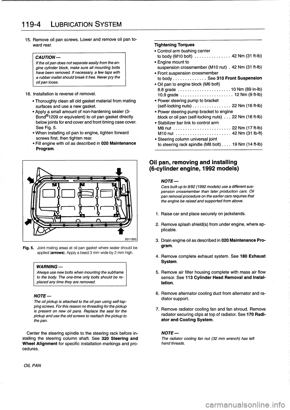
0011950
Fig
.
5
.
Joint-mating
areas
at
oil
pan
gasket
where
sealer
should
be
applied
(arrows)
.
Apply
a
bead
3
mm
wideby
2
mm
high
.
OIL
PAN
WARNING
-
Always
use
new
bolis
when
mounting
the
subframe
to
the
body
.
The
one-timeonly
bolis
shouldbe
re-
placed
any
timethey
are
removed
.
NOTE-
The
oil
pickup
is
attached
to
the
oil
pan
using
self-tap-
ping
screws
.
For
this
reasonno
threading
for
the
pickup
is
present
on
new
oil
pans
.
Replace
the
seal
for
the
pickup
and
use
the
oíd
screws
to
rea
ttach
the
pickup
to
the
pan
.
Oil
pan,
removing
and
installing
(6-cylinder
engine,
1992models)
NOTE-
Cars
built
up
to
9/92
(1992models)usea
different
sus-
pension
crossmember
than
later
production
cars
.
Oil
pan
removalprocedureon
the
earlier
cars
requires
that
the
engine
be
raised
and
supportedfrom
above
.
1
.
Raise
car
and
place
securely
on
jackstands
.
2
.
Remove
splash
shield(s)
from
under
engine,
where
ap-
plicable
.
3
.
Drain
engine
oil
as
described
in
020
Maintenance
Pro-
gram
.
4
.
Remove
complete
exhaust
system
.
See180
Exhaust
System
.
5
.
Remove
air
filter
housing
complete
with
mass
air
flow
sensor
.
See
113
Cylinder
Head
Removal
and
Instal-
lation
.
6
.
Remove
alternator
cooling
duct
from
alternator
and
ra-
diator
support
.
7
.
Remove
radiator
cooling
fan
and
fan
shroud
.
Remove
radiator
securing
clips
at
top
of
radiator
.
See
170
Radi-
ator
and
Cooling
System
.
Center
the
steering
spindle
to
the
steering
rack
before
in-
NOTE-
stalling
the
steering
column
shaft
.
See
320
Steering
and
The
radiator
cooling
fan
nut(32
mm
wrench)
has
left
Wheel
Alignment
for
specific
installation
markings
and
pro-
hand
threads
.
cedures
.
Page 120 of 759
119-
6
LUBRICATION
SYSTEM
17
.
Raise
engine
as
much
as
possible
.
Check
carefully
for
22
.
Installation
is
reverse
of
removal
.
obstructions,
wiring
harness
clearance
and
pinched
hoses
or
lines
as
engine
is
raised
.
"
When
installing
oil
pan,
apply
a
b
d
of
non-hardening
sealing
compound
(3-Bond
1209
0
or
equivalent)
to
18
.
Remove
oil
pan
mounting
bolts
and
lower
oil
pan
to
front
and
rear
end
cover
seam
areas
on
block
.
subframe
crossmember
.
"
Position
oil
pump
pickup
tube
and
oil
pan
onto
block
and
install
pickup
tube
using
a
new
gasket
.
"
Be
sure
tab
on
gasket
faces
down
towards
intake
of
NOTE-
pickup
tube
.
If
the
oil
pan
does
not
separate
easily
from
the
engine
"
Tightenforward
oil
pan
screws
first,
then
tighten
rear
.
cylinder
block,
afew
taps
with
arubber
mallet
should
"
Fill
engine
with
oil
as
described
in
020
Maintenance
break
it
free
.
Do
not
pry
the
oil
pan
loose
.
Program
.
"
After
adding
engine
oil,
start
and
run
engine
.
Raise
en-
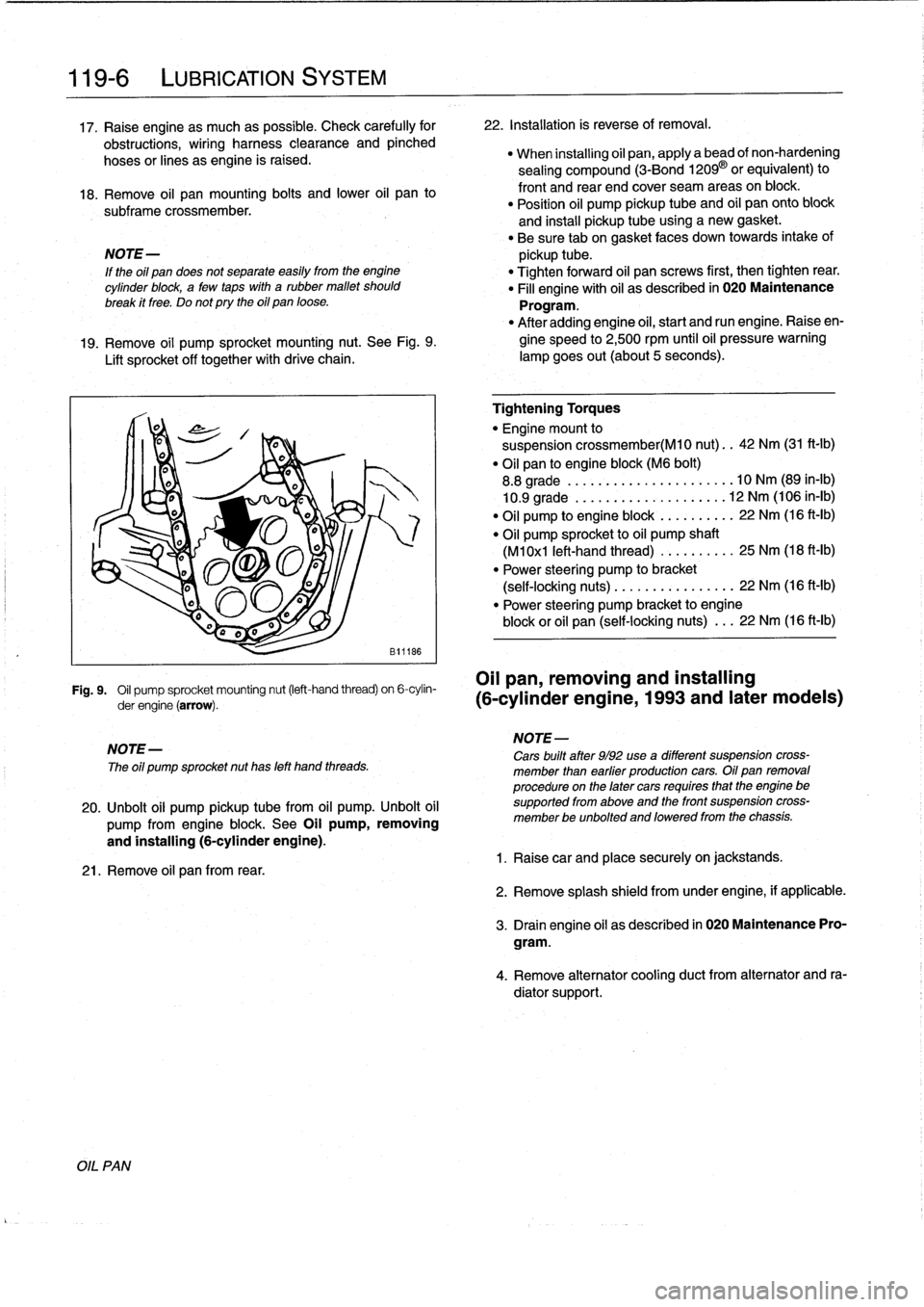
19
.
Remove
oil
pump
sprocket
mounting
nut
.
See
Fig
.
9
.
gine
speed
to
2,500
rpm
until
oil
pressure
warning
Lift
sprocket
off
together
with
drive
chain
.
lampgoes
out(about
5seconds)
.
Fig
.
9
.
Oil
pump
sprocket
mounting
nut
(left-hand
thread)
on
6-cylin-
OII
pan,
removing
and
installing
derengine(arrow)
.
(6-cylinder
engine,
1993
and
later
modeis)
NOTE-
The
oíl
pump
sprocket
nut
has
left
hand
threads
.
20
.
Unbolt
oil
pump
pickup
tubefrom
oil
pump
.
Unbolt
oil
pump
from
engine
block
.
See
Oil
pump,
removing
and
installing
(6-cylinder
engine)
.
21
.
Remove
oil
pan
from
rear
.
Tightening
Torques
"
Engine
mount
to
suspension
crossmember(M10
nut)
..
42
Nm
(31
ft-Ib)
"
Oil
pan
to
engine
block
(M6
bolt)
8
.8
grade
....
..
.
...
...
.
........
10
Nm
(89
in-lb)
10
.9
grade
.
.
..
.
..
...
.
.
.
.
.
.....
12
Nm
(106
in-lb)
"
Oil
pump
to
engine
block
.
...
...
.
..
22
Nm
(16
ft-Ib)
"
Oil
pump
sprocket
to
oil
pump
shaft
(M1
0x1
left-hand
thread)
...
..
.
.
..
.
25
Nm
(18
ft-Ib)
"
Power
steering
pump
to
bracket
(self-locking
nuts)
.....
.
....
..
.
...
22
Nm
(16
ft-lb)
"
Power
steering
pump
bracket
to
engine
block
or
oil
pan
(self-locking
nuts)
.
..
22
Nm
(16
ft-Ib)
NOTE-
Cars
built
after
9/92
use
a
different
suspension
cross-
member
¡han
earfier
productíon
cars
.
Oil
pan
removal
procedure
on
the
later
cars
requíres
that
the
engine
be
supported
from
aboye
and
the
front
suspension
cross-
member
be
unbolted
and
loweredfrom
the
chassis
.
1
.
Raisecar
and
place
securely
on
jackstands
.
2
.
Remove
splash
shield
fromunder
engine,
if
applicable
.
3
.
Drain
engine
oil
as
descríbed
in
020
Maintenance
Pro-
gram
.
4
.
Remove
alternator
cooling
duct
from
alternator
and
ra-
diator
support
.