Code 21 BMW 328i 1998 E36 Workshop Manual
[x] Cancel search | Manufacturer: BMW, Model Year: 1998, Model line: 328i, Model: BMW 328i 1998 E36Pages: 759
Page 5 of 759
Foreword
This
service
manual
covers
1992
through
1998
BMW
3
Series
models,
and
is
specifically
de-
signed
to
cover
only
those
models
built
for
sale
in
the
United
States
.
BMW,
and
most
accessories
and
parts
sellers
specializing
in
BMWs,
refer
to
the
3
Seriescars
coveredby
this
manual
as
the
E36
model
.
The
code
"E36"
is
BMW's
internal
code
for
the
basic
plat-
form
sharedby
al¡
of
the
cars
coveredby
this
manual
.
Except
for
the
engine
and
a
few
other
compo-
nents,
the
models
coveredby
this
manual
share
many
of
same
components
suchas
suspension
parts,
body
panels,
and
the
interior
pieces
.
When
ordering
parts,
especially
body
parts,
knowing
the
E36
code
may
be
helpful
.
BMW
also
usesan
interna¡
code
for
the
enginesused
in
the
3
Series
models
.
Consult
the
text
in
the
100
Engine-General
repair
group
ofthis
manual
for
a
complete
listing
of
engine
codes
.
Engine
-
code
information
is
primarily
used
internally
by
BMW,
but
may
be
helpful
if
you
haveaccess
to
BMW
technical
information
.
Forthe
BMW
ownerwith
basic
mechanical
skills,
this
manual
gives
detailed
maintenance
and
re-
pair
information
.
In
addition,
the
BMW
owner
who
hasno
intention
of
working
on
his
or
her
own
car
will
findthat
owning
and
reading
this
manual
will
make
it
possibleto
be
better
informed
and
todis-
cuss
repairs
more
intelligently
with
a
professional
technician
.
This
manual
has
been
prepared
from
the
repair
information
that
BMW
provides
to
its
factory-trained
technicians
and
has
been
developed
primarily
with
the
do-it-yourself
BMW
owner
in
mind
.
The
aim
throughout
has
been
clarity
and
un-
derstanding
with
practical
descriptions,
step-by-step
procedures,
and
accurate
specifications
.
The
BMW
owner
intending
to
do
maintenance
and
repair
should
have
a
set
of
tools
including
a
set
of
metric
wrenches
and
sockets,
screwdrivers,
a
torque
wrench,
and
feeler
gauges,
since
these
ba-
sic
tools
will
beused
to
do
the
majority
of
the
maintenance
and
repair
procedures
described
in
this
manual
.
This
manual
includes
detailed
information
onthese
basic
tools
and
other
tips
for
the
begin-
ner
in
the
first
section
of
the
manual,
entitled
010
Fundamentals
for
the
Do-It-Yourself
Owner
.
For
some
of
the
repairs
described
in
this
manual,
BMW
technicians
use
special
tools
.
The
text
will
note
when
a
repair
requires
these
special
tools
and,
where
possible,
will
recommend
practica¡
alter-
natives
.
Page 8 of 759
Please
read
these
warnings
and
cautions
before
proceeding
with
maintenance
and
repair
work
.
CAUTION-
"
See
also
Warnings
onpage
vi¡
"
Beforedoing
any
electrical
welding
on
cars
equipped
with
ABS,
disconnect
the
battery
negative
(-)
terminal
(ground
strap)
and
the
"
If
you
lack
the
skills,
tools
and
equipment,
ora
suitable
work-
ABS
control
unit
connector
.
shop
for
any
procedure
described
in
this
manual,
we
suggest
you
leave
such
repairs
to
an
authorized
BMW
dealer
or
other
qualified
"
On
cars
equipped
with
anti-theft
radios,
make
sureyou
know
the
shop
.
correct
radio
activation
code
before
disconnecting
the
battery
or
removing
the
radio
.
lf
the
wrong
code
is
entered
into
the
radio
"
BMW
is
constantly
improving
its
cars
and
sometimes
these
when
power
is
restored,
that
radio
may
lock
up
and
be
renderedchanges,
both
in
parts
and
specifications,
are
made
applicable
to
inoperable,
even
if
the
correct
code
is
thenentered
.
earlier
models
.
Therefore,
part
numbers
listed
in
this
manual
are
for
reference
only
.
Always
check
with
your
authorized
BMW
dealer
"
Always
make
sure
ignition
is
off
before
disconnecting
battery
.
parts
department
for
the
latest
information
.
"
Label
battery
cablesbefore
disconnecting
.
Onsome
models,
"
Before
starting
a
job,
make
certain
that
you
have
all
the
neces-
battery
cablesarenot
color
coded
.
sary
tools
and
parts
on
hand
.
Read
al¡
the
instructions
thoroughly,
do
not
attempt
shortcuts
.
Use
tools
appropriate
to
the
work
and
"
Disconnecting
the
battery
may
erase
fault
code(s)
stored
in
con-
use
only
replacement
parts
meeting
BMW
specifications
.
Make-
trol
module
memory
Using
special
BMW
diagnostíc
equipment,
shift
tools,
parts
and
procedures
will
not
make
good
repairs
.
check
forfault
codes
prior
to
disconnecting
the
battery
cables
.If
the
Check
Engine
light
is
illuminated,
see100
Engine-General
for
"
Use
pneumatic
and
electric
tools
only
to
loosenthreaded
parts
On-Board
Diagnostics
(OBD)
fault
code
information
.
lf
any
other
and
fasteners
.
Never
use
these
tools
to
tighten
fasteners,
espe-
system
faults
have
been
detected
(indicated
by
an
ílluminated
cially
on
light
alloy
parts
.
Always
use
a
torque
wrench
to
tighten
warning
light),
see
an
authorized
BMW
dealer
.
fasteners
to
the
tightening
torque
specification
listed
.
"
If
a
normal
or
rapid
charger
is
used
to
charge
battery,
the
battery
"Be
mindful
of
the
environment
and
ecology
.
Before
you
drain
the
mustbe
disconnected
and
removed
fromthe
vehicle
in
order
to
crankcase,
find
outthe
proper
way
to
dispose
of
the
oil
.
Do
not
avoid
damaging
paint
and
upholstery
pour
oil
onto
the
ground,
down
a
drain,
or
into
a
stream,
pond
orlake
.
Dispose
of
in
accordance
withFederal,
State
and
Local
laws
.
"Do
not
quick-chargethe
battery
(for
boost
starting)
for
longer
than
one
minute
.
Wait
at
least
one
minute
before
boosting
the
bat-
e
If
battery
power
is
lost
or
the
battery
has
been
disconnected,
the
tery
a
second
time
.
powerwindows
must
be
re-initialized
.
Both
one
touch
up/down
and
pinch-protection
will
be
inactive
until
windows
are
re-initial-
"
Connect
and
disconnect
a
battery
charger
only
with
the
battery
ized
.
See
512
Door
Windows
.
charger
switched
off
.
"
The
control
module
for
the
anti-lock
brake
system
(ABS)
cannot
withstand
temperatures
from
a
paint-drying
booth
or
aheat
lamp
in
excess
of
203°F
(95°C)
and
should
not
be
subjected
to
temper-
atures
in
excess
of
185°F
(85°C)
for
more
than
twohours
.
"
Sealed
or
"maintenance
free"
batteries
shouldbeslow-charged
only,
at
anamperage
ratethat
is
approximately
10%
of
the
bat-
tery's
ampere-hour
(Ah)
rating
.
"
Do
not
allow
battery
chargingvoltage
to
exceed
16
.5
volts
.
If
the
battery
begins
producing
gas
or
boiling
violently,
reduce
the
charg-
ing
rate
.
Boosting
a
sulfated
battery
at
a
high
charging
rate
can
cause
an
explosion
.
Page 15 of 759
Non-returnable
Parts
FUNDAMENTALS
FOR
THEDO-ITYOURSELF
OWNER
010-
7
Many
independent
repair
shops
make
a
point
of
using
genu-
Original
body
paneis
and
other
large
components
are
identi-
ine
BMW
parts,
even
though
they
may
at
times
be
more
expen-
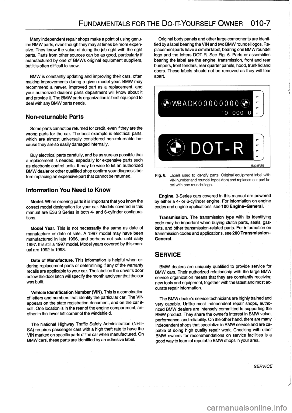
fied
by
a
label
bearing
the
VINand
two
BMW
roundellogos
.
Re-
sive
.
Theyknow
the
value
of
doing
thejob
right
with
the
right
placement
parts
have
a
similar
label,
bearing
one
BMW
roundel
parts
.
Parts
from
other
sources
can
beas
good,
particularly
if
logo
and
the
letters
DOT-R
.
See
Fig
.
6
.
Parts
or
assemblies
manufactured
by
one
of
BMWs
original
equipment
suppliers,
bearing
the
label
arethe
engine,
transmission,
front
and
rear
but
it
is
often
difficult
to
know
.
bumpers,
front
fenders,
rear
quarter
paneis,
hood,
trunk
lid
and
doors
.
These
labels
shouldnot
be
removed
as
they
will
tear
BMW
is
constantly
updating
and
improving
their
cars,
often
apart
.
making
improvements
during
a
given
model
year
.
BMW
may
recommend
a
newer,
improved
part
as
a
replacement,
and
your
authorized
dealer's
parts
department
will
know
about
it
and
provide
it
.
The
BMW
parts
organization
is
best
equipped
to
deal
with
any
BMW
parts
needs
.
Some
parts
cannot
be
returned
for
credit,
even
if
they
arethe
wrong
parts
forthe
car
.
The
best
example
is
electrical
parts,
which
are
almost
universally
considered
non-returnable
be-
,
..
cause
they
are
so
easily
damaged
internally
.
Buy
electrícal
parts
carefully,
and
beas
sure
as
possible
that
P-
DOT~
R
a
replacement
is
needed,
especially
for
expensive
parts
such
as
electronic
control
units
.
It
may
bewise
to
let
an
authorized
B328FUN
BMW
dealeror
other
qualified
shop
confirm
your
diagnosisbe-
fore
replacing
an
expensive
part
that
cannot
be
retuned
.
Fig
.
6
.
Labels
used
to
identiy
parts
.
Original
equipment
labelwith
VIN
number
and
roundel
logos
(top)
and
replacement
part
la-
bel
with
one
roundel
logos
Information
You
Need
to
Know
Engine
.
3-Seriescars
covered
in
this
manualare
powered
Model
.
When
ordering
parts
it
is
important
that
you
know
the
by
either
a
4-or
6-cylinder
engine
.
For
information
-
on
engine
correct
model
designation
for
your
car
.
Models
covered
in
this
codes
and
engine
applications,
see100
Engine-General
.
manual
are
E36
3
Series
in
both
4-
and
6-cylinderconfigura-
tions
.
Transmission
.
The
transmissiontype
with
its
identifying
code
may
be
important
when
buying
clutch
parts,
seals,
gas
Moda¡
Year
.
This
is
not
necessarily
the
same
as
date
of
kets,
and
othertransmission-relatedparts
.
For
information
on
manufacture
or
date
of
sale
.
A
1997
model
may
havebeen
transmission
codes
and
applications,
see200
Transmission
manufactured
in
late
1996,
and
perhaps
not
sold
until
early
General
.
1997
.
It
is
still
a1997
model
.
Model
years
covered
by
this
man-
ual
are
1992
to
1998
.
SERVICE
Date
of
Manufacture
.
This
information
is
helpful
when
or-
dering
replacement
parts
or
determining
if
any
of
the
warranty
BMW
dealers
are
uniquely
qualified
to
provide
service
for
recalls
are
applicable
to
your
car
.
The
label
on
the
driver's
door
BMW
cars
.
Their
authorized
relationship
with
the
large
BMW
below
the
door
latch
will
specify
the
month
and
year
that
the
car
serviceorganization
means
that
they
are
constantly
receiving
was
built
.
new
tools
and
equipment,
together
with
the
latest
and
most
ac-
curate
repair
information
.
Vehicle
Identification
Number
(VIN)
.
This
is
a
combination
of
letters
and
numbers
that
identify
the
particular
car
.
TheVIN
appears
on
the
state
registration
document,
and
on
thecar
it-
self
.
One
location
isin
the
rear
of
the
engine
compartment,
en-
other
in
the
lower
left
comer
of
the
windshield
.
The
National
Highway
Traffic
Safety
Administration
(NHT-
SA)
requires
passenger
cars
with
a
high
theftrateto
have
the
VINmarked
on
specific
parts
of
thecar
when
manufactured
.
On
BMW
cars,
these
parts
are
identified
byan
adhesive
label
.
)WBADK00000000
0
000
0
The
BMW
dealers
service
technicians
are
highlytrained
and
very
capable
.
Unfke
most
independent
repair
shops,
autho-
rized
BMW
dealers
are
intensely
committed
tosupporting
the
BMW
product
.
They
share
the
owners
interest
in
BMW
value,
performance,
and
reliability
.
On
the
other
hand,
there
are
many
independent
shops
that
specialize
in
BMW
service
and
are
ca-
pable
of
doing
high
quality
repair
work
.
Checking
with
other
BMW
owners
for
recommendations
on
service
facilitiesis
a
good
way
to
leam
of
reputable
BMW
shops
in
yourarea
.
SERVICE
Page 37 of 759
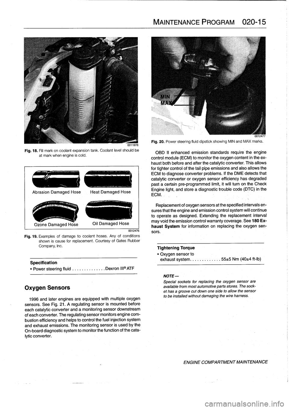
Fig
.
18
.
Fill
mark
on
coolant
expansion
tank
.
Coolant
level
should
be
at
mark
when
engine
ís
cold
.
.
..
e
..
.-
..
~
..
.-
.
Ozone
Damaged
Hose
0012476
Fig
.
19
.
Examples
of
damage
to
coolant
hoses
.
Any
of
conditions
shown
is
cause
for
replacement
.
Courtesy
of
Gates
Rubber
Company,
Inc
.
Specification
"
Power
steering
fluid
..........
.
...
Dexron
III®ATF
Oxygen
Sensors
1996
and
later
engines
are
equipped
withmultiple
oxygen
sensors
.
See
Fig
.
21
.
A
regulating
sensor
is
mounted
before
each
catalytic
converter
and
amonitoring
sensor
downstream
of
each
converter
.
The
regulating
sensor
monitors
engine
com-
bustion
efficiency
and
helps
to
control
the
fuel
injection
system
and
exhaust
emissions
.
The
monitoring
sensor
is
usedby
the
On-board
diagnostic
system
to
monitor
the
function
of
the
cata-
lytic
converter
.
MAINTENANCE
PROGRAM
020-
1
5
NOTE-
5pecialsockets
for
replacingthe
oxygen
sensor
are
available
from
most
automotive
parts
stores
.
The
sock-
et
has
agroove
cut
down
one
side
to
allow
the
sensor
to
be
installed
without
damaging
the
wire
hamess
.
Fig
.
20
.
Power
steering
fluid
dipstick
showing
MIN
and
MAX
marks
.
OBD
II
enhanced
emission
standards
require
the
engine
control
module
(ECM)
to
monitor
the
oxygen
content
in
theex-
haust
bothbefore
and
after
the
catalytic
converter
.
This
allows
for
tightercontrol
of
the
tail
pipe
emissions
and
also
allowsthe
ECM
to
diagnose
converter
problems
.
lf
the
DME
detects
that
catalytic
converter
or
oxygen
sensor
efficiency
has
degraded
past
a
certain
pre-programmed
limit,
it
will
turn
on
the
Check
Engine
light,
and
store
a
diagnostic
trouble
code
(DTC)
in
the
ECM
.
Replacement
of
oxygen
sensors
at
the
specified
intervals
en-
sures
that
the
engine
and
emission
control
system
wíll
continue
to
operate
as
designed
.
Extending
the
replacement
interval
may
void
the
emission
control
warranty
coverage
.
See
180
Ex-
haust
System
for
information
on
replacing
the
oxygen
sen-
sors
.
Tightening
Torque
"
Oxygen
sensor
to
exhaust
system
........
.
.
.
..
55±5
Nm
(40±4
ft-Ib)
ENGINE
COMPARTMENT
MAINTENANCE
Page 43 of 759
GENERAL
.
.....
.
.
.
.
.
.
.
...
.
.
.
.
.
.
.
.
.
...
100-1
Cylinder
Block
and
Crankshaft
.
.
.
.
.
.
.
.
.
...
100-1
Connecting
Rods
and
Pistons
.
.
.
.
.
.
.
.
.
.
.
.
.
100-1
Cylinder
Head
and
Valvetrain
.
.
.
.
.
.
.
.
.
.
.
.
.
100-2
VANOS
(Variable
Valve
Timing)
.
.
.
.
.
.
.
.
...
100-2
DISA
(Dual
Resonance
Intake
System)
.
.
.
.
.
100-3
Engine
Management
System
.
.
.
.
.
.
.
.
.
.
.
.
.
100-3
Ignition
......
.
.
.
.........
.
.
.
.
.
.
.
.
.
.
.
.
100-5
Fuel
Delivery
..
.
.
.
.....
.
...
.
.
.
.
.
.
.
.
.
.
.
.
100-5
Cooling
System
.
...........
.
.
.
.
.
.....
.
.
100-5
Lubrication
System
.........
.
.
.
.
.
.
.
.
.
.
.
.
100-5
MECHANICALTROUBLESHOOTING
.
.
.
.
100-5
Warnings
and
Cautions
..
.
...
.
.
.
.
.
.
.
.
.
.
.
.
100-5
Cylinder
compression,
checking
.
.
.
.
.
.
.
.
.
.
.
100-6
EngineMechanical
Troubleshooting
Table
.
.
.
100-7
DRIVEABILITY
TROUBLESHOOTING
...
100-8
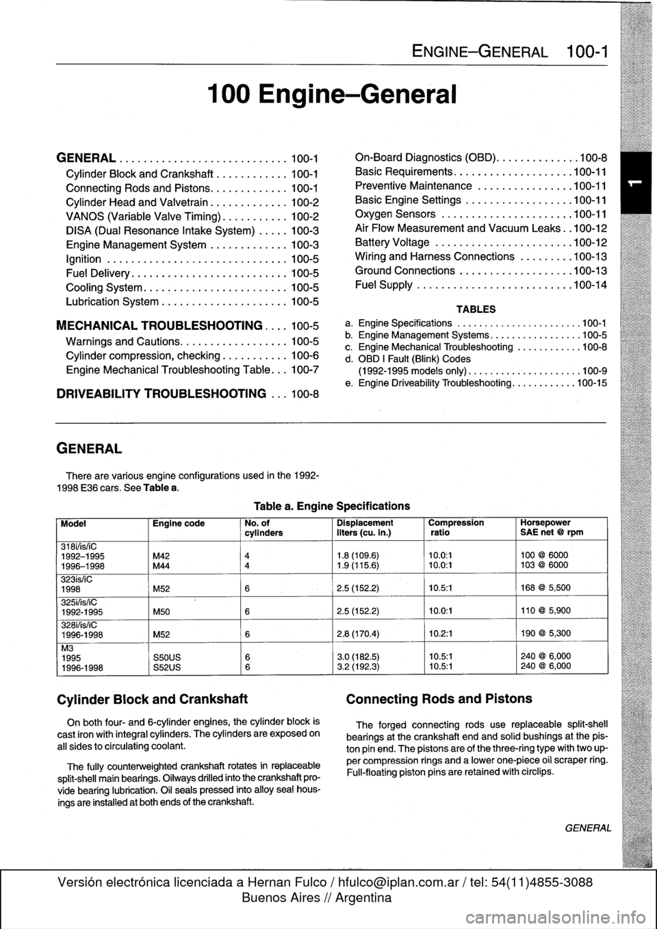
GENERAL
There
are
various
engíne
configurations
used
in
the
1992-
1998
E36
cars
.
See
Table
a
.
On
both
four-
and
6-cylinder
engines,
the
cylinder
block
is
cast
¡ron
with
integral
cyiinders
.
The
cyiinders
are
exposed
on
all
sides
to
circulating
coolant
.
The
fully
counterweighted
crankshaft
rotates
in
replaceable
split-shell
main
bearings
.
Oiiways
drilled
into
the
crankshaft
pro-
vide
bearing
lubrication
.
O¡I
seals
pressed
into
alloy
sea¡
hous-
ings
are
installedat
both
ends
of
the
crankshaft
.
100
Engine-General
Tablea
.
Engine
Specifications
ENGINE-GENERAL
100-1
On-Board
Diagnostics
(OBD)
...
.
.
.
.
.
.
.
.
.
.
.
100-8
Basic
Requirements
....
.
.
.
...
.
.
.
.
.
....
.100-11
Preventive
Maintenance
......
.
.
.
.
.
.....
100-11
Basic
Engine
Settings
..
.
.....
.
.
.
.
.
.....
100-11
Oxygen
Sensors
.
.
.
...
.
.
.
...
.
.
.
.
.
....
.100-11
Air
Flow
Measurement
and
Vacuum
Leaks
.
.100-12
Battery
Voltage
.
.
...........
.
.
.
.
.
.....
100-12
Wiring
and
Harness
Connections
.
.
.
.
.....
100-13
Ground
Connections
...
.
.....
.
.
.
.
.
.....
100-13
Fue¡
Supply
....
.
...........
.
.
..
.....
.100-14
TABLES
a
.
Engine
Specifications
...
...
...........
.
..
..
.100-1
b
.
Engine
Management
Systems
..
..
...........
..
100-5
c
.
Engine
Mechanical
Troubleshooting
..........
.
.
100-8
d
.
OBD
1
Fault
(Blink)
Codes
(1992-1995
models
only)
.
...
..
..
..........
..
.100-9
e
.
Engine
Driveability
Troubleshooting
...........
.100-15
Model
Engine
code
No
.
of
Dispiacement
Compression
Horsepower
cyiinders
liters
(cu
.
in
.)
ratio
SAE
net
@
rpm
318i/is/¡C
1992-1995
M42
4
1
.8
(109
.6)
10
.0
:1
100
@
6000
1996-1998
M44
4
1
.9
(115
.6)
~
10
.0
:1
103
@
6000
323ís/iC
1998
M52
6
2
.5
(152
.2)
10
.5
:1
168
@
5,500
325i/is/iC
1992-1995
M50
6
2
.5
(152
.2)
10
.0
:1
110
@
5,900
328i/is/iC
1996-1998
M52
6
2
.8
(170
.4)
10
.2
:1
190
@
5,300
M3
1995
S50US
6
3
.0
(182
.5)
10
.5:1
240
@
6,000
1996-1998
S52US
6
3
.2
(192
.3)
10
.5:1
240
@
6,000
Cylinder
Block
and
Crankshaft
Connecting
Rods
and
Pistons
The
forged
connecting
rods
use
replaceable
split-shell
bearings
at
the
crankshaft
endand
solid
bushings
at
the
pis-
ton
pin
end
.
The
pistonsare
of
the
three-ring
typewith
two
up-
per
compression
rings
and
a
lowerone-piece
o¡i
scraper
ring
.
Fui¡-floating
piston
pins
are
retained
with
circlips
.
GENERAL
Page 47 of 759
ignition
Table
b
.
Engine
Management
Systems
engine
has
high
mileage
.
Engine
1
System
4-cylinder
engines
M42
(1992-1995)
Bosch
DME
Ml
.7
M44
(1996-1998)
Bosch
DME
M5
.2
(OBD
II)
6-cylinder
engines
M50
(1992)
Bosch
DME
M3
.1
M50
VANOS
(1993-1995)
Bosch
DME
M3
.3
.1
M52
(1996-1998)
Siemens
MS41
.1
(OBD
II)
S50US
(1995)
Bosch
DME
M3
.3
.1
S52US
(1996-1998)
Siemens
MS41
.1
(OBD
II)
Both
the
4-cylinder
and
6-cylinder
engines
use
a
distributor-
less
ignition
system
with
individual
ignition
coils
for
each
cylin-
der
.
FuelDelivery
Pressurized
fuel
from
the
in-tank
fuel
pump
is
injected
via
solenoid-type
fuel
injectors
.
The
ECM
controls
the
opening
and
closing
of
the
injectors
by
switchingthe
ground
side
of
each
injector
circuit
.
The
exact
amount
of
fuel
injected
is
de-
termined
by
the
amount
of
timethe
injectors
are
open
.
Cooling
System
Whenever
the
engine
is
running,
acoolant
pump
circulates
coolant
through
the
engine
and,
if
either
heater
control
valves
are
open,
through
the
heater
core
in
the
passenger
compart-
ment
.
The
coolant
absorbs
excess
heat
and
carries
it
to
the
ra-
diator
where
it
is
transferred
into
the
passing
airstream
.
A
thermostat
controls
the
flow
of
coolant
through
the
radiator
based
on
engine
temperature
.
Lubrication
System
The
lubrication
system
is
pressurized
whenever
theengine
is
running
.
The
oil
pump
draws
oil
through
a
pickup
in
the
bot-
tom
of
the
oil
pan,thenforces
it
through
a
replaceable
oil
filter
and
finto
the
engine
oíi
passages
.
On
4-cylinder
engines,
the
oil
pump
is
mounted
to
the
front
engine
cover
.
On
6-cylinder
engines,thechain-driven
oil
pump
is
bolted
to
the
bottom
of
the
cylinder
block
.
A
pressure
relief
valve
limits
the
maximum
system
pres-
sure
.
A
bypass
valve
prevents
the
oil
filter
from
bursting
and
insures
engine
lubrication
should
the
filter
become
plugged
.
See
119
Lubrication
System
for
additional
information
.
ENGINE-GENERAL
100-
5
Various
versions
of
DME
systems
are
usedon
thecars
cov-
MECHANICAL
TROUBLESHOOTING
ered
by
this
manual
.
See
Table
b
.
Each
system
is
highly
adaptive
to
compensate
for
things
suchasengine
wear
and
When
troubleshooting
an
engine
that
fails
to
start
or
runs
vacuum
leaks
.
poorly,
first
check
its
mechanical
condition-particularly
if
the
Warnings
and
Cautions
For
personal
safety,
as
well
asthe
protection
of
sensitive
electronic
components,
the
following
warnings
and
cautions
must
be
adhered
to
during
all
troubleshooting,
maintenance,
and
repairwork
.
WARNING
-
"
The
ignition
system
produces
high
voltages
that
can
be
fatal
.
Avoid
contact
with
exposed
termi-
nals
anduse
extreme
caution
when
working
on
a
car
with
the
ignition
switched
on
or
the
engine
running
.
"
Do
not
touch
or
disconnect
any
high
voltage
ca-
bles
from
the
coil,
distributor,
orspark
plugs
while
the
engine
is
running
or
being
cranked
by
the
starter
"
Connect
and
disconnect
the
engine
manage-
ment
system
wiring
and
test
equipment
leads
only
when
the
ignition
is
switched
off
.
"
Gasoline
is
highly
flammable
and
its
vapors
are
explosive
.
Do
not
smoke
or
work
on
a
car
near
heaters
or
other
fire
hazards
when
diagnosing
and
repairing
fuel
system
problems
.
Have
a
fire
extínguisher
available
in
case
of
an
emergency
.
"
Disconnecting
the
battery
may
erase
fault
code(s)
stored
in
control
module
memory
.
Using
special
BMW
diagnosnnc
equipment,
check
for
fault
codes
prior
to
disconnecting
the
battery
cables
.
If
the
Check
Engine
lightis
illuminated,
see
On-
Board
Diagnostics
(OBD)
forfault
code
infor-
mation
.
If
any
other
system
faults
havebeen
de-tected
(indicated
byan
illuminated
warning
light),
see
an
authorized
BMW
dealer
.
CAUTION-
"
Prior
to
disconnecting
the
battery,
read
the
bat-
tery
disconnection
cautions
gíven
at
the
front
of
this
manual
on
page
viii
.
"
Do
notconnect
any
test
equipment
that
delivers
a
12-volt
power
supply
to
terminal15
(+)
of
the
ignition
coil
.
The
current
flow
may
damage
the
ECM
.
In
general,
connect
test
equipment
only
as
specified
by
BMW,
this
manual,
or
the
equip-
ment
maker
.
"
Do
not
disconnect
the
battery
with
the
engine
running
.
Do
notrunthe
engine
with
any
of
the
sparkplug
wires
disconnected
.
MECHANICAL
TROUBLESHOOTING
Page 50 of 759
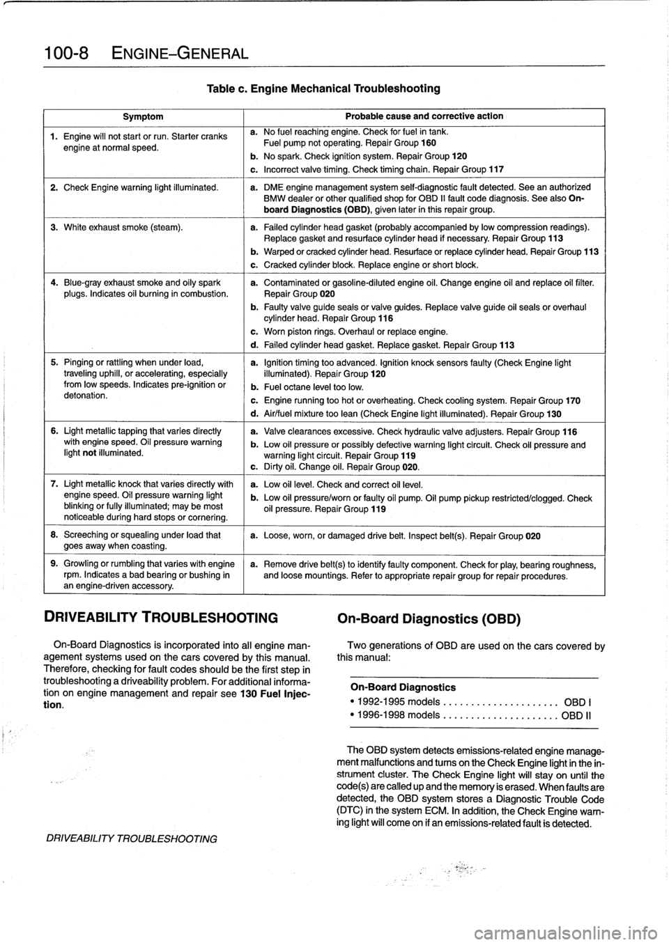
100-8
ENGINE-GENERAL
Symptom
1
Probable
cause
and
correctiveaction
1
.
Engine
will
not
start
or
run
.
Starter
cranks
a
.
No
fuel
reaching
engine
.
Check
forfuelin
tank
.
engine
at
normal
speed
.
Fuel
pump
notoperating
.
Repair
Group
160
b
.
No
spark
.
Check
ignition
system
.
Repair
Group
120
c
.
Incorrect
valve
timing
.
Check
timing
chain
.
Repair
Group
117
2
.
Check
Engine
warning
light
illuminated
.
a
.
DME
engine
management
system
self-diagnostic
fault
detected
.
Sea
an
authorized
BMW
dealer
or
other
qualified
shop
for
OBD
II
fault
code
diagnosis
.
See
also
On-
board
Diagnostics(OBD),
given
later
inthis
repair
group
.
3
.
White
exhaust
smoke
(steam)
.
a
.
Failed
cylinder
head
gasket
(probably
accompanied
bylowcompression
readings)
.
Replace
gasket
and
resurface
cylinder
head
if
necessary
.
Repair
Group
113
4
.
Blue-gray
exhaust
smoke
and
oily
spark
a
.
Contaminated
or
gasoline-diluted
engine
oil
.
Change
engine
oil
and
replace
oil
filter
.
plugs
.
Indicates
oii
burning
in
combustion
.
Repair
Group
020
b
.
Faulty
valve
guide
seals
or
valve
guides
.
Replace
valve
guide
oil
seals
or
overhaul
cylinder
head
.
Repair
Group
116
5
.
Pinging
or
rattling
when
under
load,
a
.
Ignition
timing
too
advanced
.
Ignition
knocksensors
faulty
(CheckEngine
light
traveling
uphill,
or
accelerating,
especially
illuminated)
.
Repair
Group
120fromlow
speeds
.
Indicates
pre-ignition
or
b
.
Fuel
octane
leve¡
toolow
.
detonation
.
c
.
Engine
running
too
hot
or
overheating
.
Check
cooling
system
.
Repair
Group
170
6
.
Light
metallic
tapping
that
varies
directly
with
engine
speed
.
Oil
pressure
warning
light
not
illuminated
.
7
.
Light
metallic
knock
that
varies
directly
with
enginespeed
.
Oil
pressure
warning
light
blinking
or
fully
illuminated
;
may
be
most
noticeable
during
hard
stops
or
cornering
.
8
.
Screeching
or
squealing
under
load
that
a
.
Loose,worn,
or
damaged
drive
belt
.
Inspect
belt(s)
.
Repair
Group
020
goesaway
when
coasting
.
9
.
Growling
or
rumbling
that
varieswith
engine
a
.
Remove
drive
belt(s)toidentifyfaulty
component
.
Check
for
play,
bearing
roughness,
rpm
.
Indicates
abad
bearing
or
bushing
in
and
loose
mountings
.
Refer
to
appropriate
repair
group
for
repair
procedures
.
an
engine-driven
accessory
.
DRIVEABILITY
TROUBLESHOOTING
On-Board
Diagnostics
(OBD)
On-Board
Diagnostics
is
incorporated
into
al¡
engine
man-
Two
generations
of
OBD
are
usedon
thecars
covered
by
agement
systems
used
on
the
cars
covered
by
this
manual
.
this
manual
:
Therefore,
checking
for
fault
codes
should
be
the
first
step
in
troubleshootinga
driveability
problem
.
For
additional
informa-
On-Board
Diagnostics
tion
on
engine
management
and
repair
see130
Fuel
Injec-
tion
.
"
1992-1995models
....
.
..
....
.
..
.......
OBD
I
"
1996-1998models
.
....
..
.
.
.
..
.
........
OBD
II
DRIVEABILITY
TROUBLESHOOTING
Tablec
.
Engine
Mechanical
Troubleshooting
b
.
Warped
or
cracked
cylinder
head
.
Resurface
or
replace
cylinder
head
.
Repair
Group
113
c
.
Cracked
cylinder
block
.
Replace
engine
or
short
block
.
c
.
Worn
piston
rings
.
Overhaul
or
replace
engine
.
d
.
Failed
cylinder
head
gasket
.
Replace
gasket
.
Repair
Group
113
d
.
Air/fuel
mixture
too
lean
(Check
Engine
light
illuminated)
.
Repair
Group
130
a
.
Valveclearances
excessive
.
Check
hydraulic
valve
adjusters
.
Repair
Group
116
b
.
Low
oil
pressure
orpossibly
defective
warning
light
circuit
.
Check
oil
pressure
andwarning
light
circuit
.
Repair
Group
119
c
.
Dirty
oil
.
Change
oil
.
Repair
Group
020
.
a
.
Low
oil
leve¡
.
Check
and
correct
oil
leve¡
.
b
.
Low
oil
pressure/worn
or
faulty
oil
pump
.
Oil
pump
pickup
restricted/clogged
.
Check
oil
pressure
.
Repair
Group
119
The
OBD
system
detects
emissions-related
engine
manage-
ment
malfunctions
and
tucos
on
the
Check
Engíne
lightin
the
in-
strument
cluster
.
TheCheck
Engine
light
will
stay
on
until
the
code(s)are
called
up
and
the
memory
is
erased
.
When
faulty
are
detected,
the
OBD
system
stores
a
Diagnostic
Trouble
Code
(DTC)
in
the
system
ECM
.
In
addition,
the
Check
Engine
warn-
ing
light
will
come
on
if
an
emissions-related
fault
is
detected
.
Page 51 of 759
NOTE-
"
On
carswith
OBD
ti,
specialized
OBD
11
scan
tool
equipment
must
be
used
to
access
the
DTCs,
either
using
the
BMW
special
tool
ora
`generic"
OBD
11
scan
tool
.
See
130
Fuel
Injection
.
"
The
08D
11
fault
memory
(including
an
iiluminated
Check
Engine
light)
can
only
be
reset
using
the
spe-
cial
scan
tool
.
Removing
the
connector
from
the
ECM
or
disconnecting
the
battery
will
not
erase
the
fault
memory
.
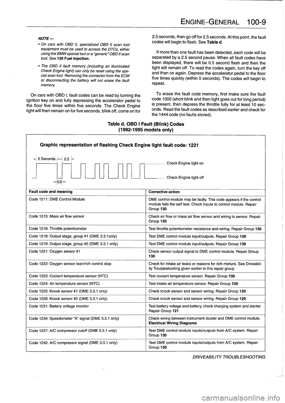
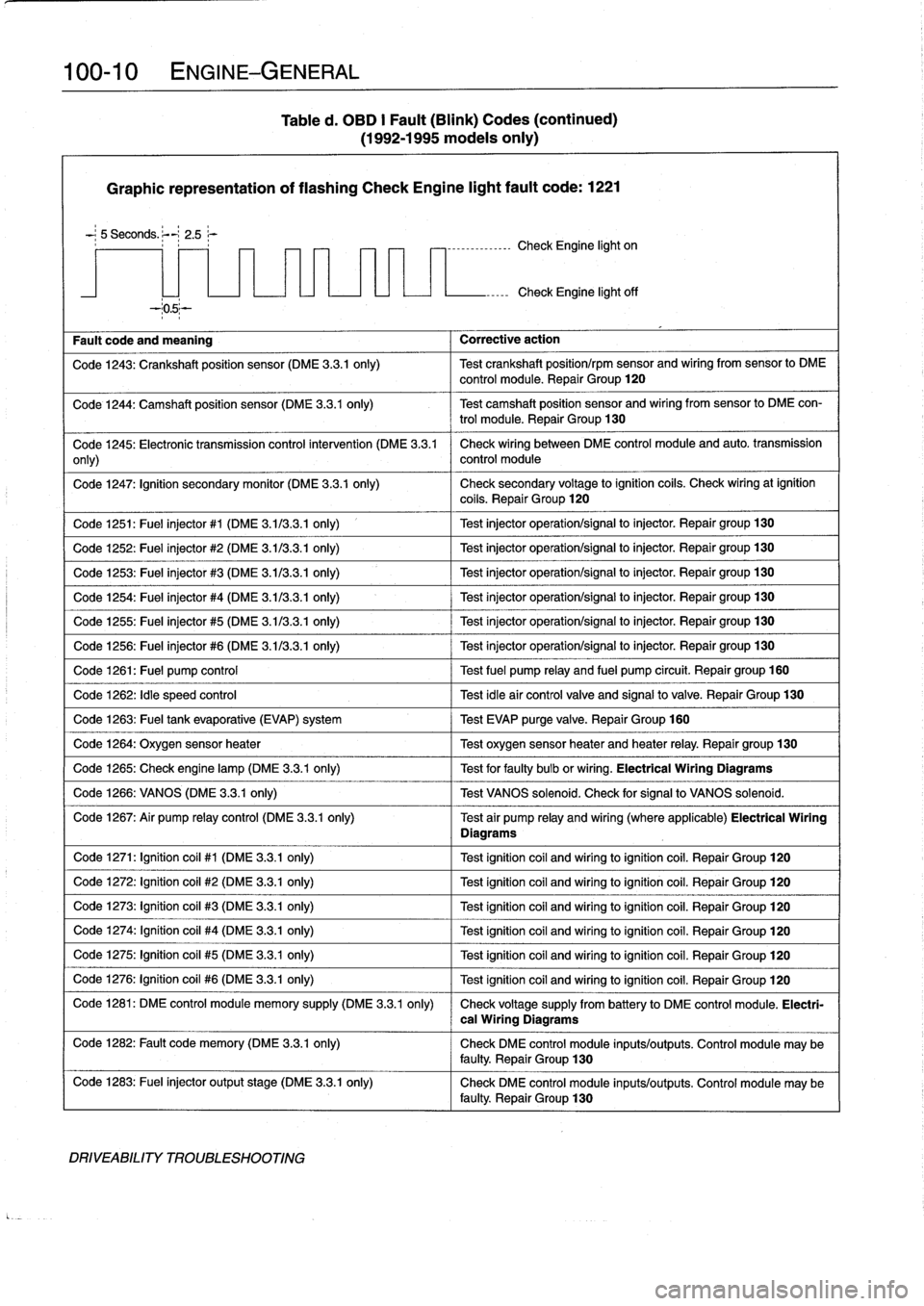
Table
d
.
OBD
1
Fault
(Blink)
Codes
(1992-1995
modeis
only)
Graphic
representation
of
flashing
Check
Engine
light
fault
code
:
1221
5
Seconds
.
:-
2
.5~-
--05--
Fault
code
and
meaning
1
Corrective
action
Code
1216
:
Throttle
potentiometer
Code
1218
:
Output
stage,
group#1
(DME
3
.3
.ionly)
Code
1219
:
Output
stage,
group
#2
(DME
3
.3.1
only)
Code
1221
:
Oxygen
sensor
#1
Code
1224
:
Air
temperature
sensor
(NTC)
Code
1226
:
Knock
sensor
#2
(DME
3
.3
.1
only)
130
ENGINE-GENERAL
100-
9
2
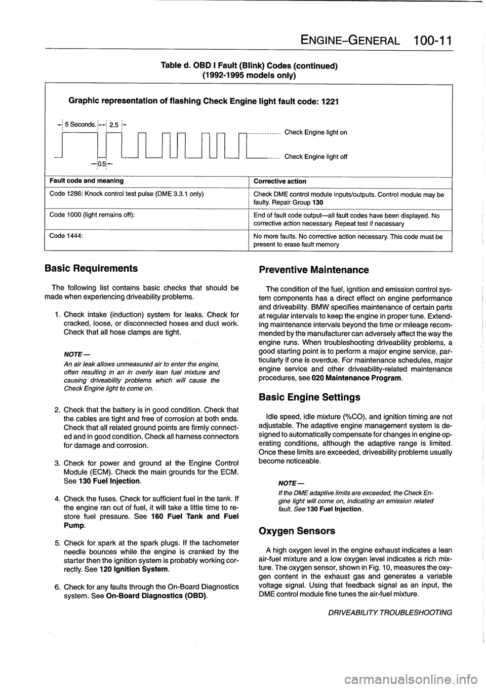
.5
seconds,
then
go
off
for
2
.5
seconds
.
At
thispoint,
the
fault
codes
will
begin
to
flash
.
See
Table
d
.
If
more
than
one
fault
has
been
detected,
eachcode
will
be
separated
by
a2
.5
second
pause
.
When
al¡
fault
codes
havebeen
displayed,
there
will
be0
.5
second
flash
and
thenthe
light
will
remain
off
.
To
read
the
codes
again,
turn
the
key
off
and
then
on
again
.
Depress
theaccelerator
pedal
to
the
floor
five
times
quickly
(within
5
seconds)
.
The
codes
will
begin
to
repeat
.
On
cars
with
OBD
I,
fault
codes
can
be
read
by
turning
the
To
erase
the
fault
code
memory,
first
make
sure
the
fault
ignition
key
on
and
fully
depressing
theaccelerator
pedal
to
code
1000
(short
blink
and
then
light
goes
out
for
long
period)
the
floor
five
times
within
five
seconds
.
TheCheck
Engine
is
present,
then
depress
the
throttle
fully
for
at
least
10
sec-
light
will
then
remain
on
for
five
seconds,
blink
off,
come
on
for
onds
.
Read
the
fault
codes
as
described
earlier
and
check
for
the
1444
code
(no
faults
stored)
.
-,--------------
Check
Engine
light
on
Check
Engine
light
off
Code
1211
:
DM
E
Control
Module
DME
control
module
may
be
faulty
.
This
code
appears
if
the
control
module
fails
the
self
test
.
Check
inputsto
control
module
.
Repair
Group
130
Code
1215
:
Mass
air
flow
sensor
Check
air
flow
or
mass
air
flow
sensor
and
wiring
to
sensor
.
Repair
Group
130
Test
throttle
potentiometer
resistance
and
wiring
.
Repair
Group
130
Test
DME
control
module
input/outputs
.
Repair
Group
130
Test
DME
control
module
input/outputs
.
Repair
Group
130
Check
sensor
output
signal
to
DME
control
module
.
Repair
Group
Code
1222
:
Oxygen
sensor
lean/rich
control
stop
Check
for
intake
air
leaks
or
reasons
forrich
míxture
.
See
Driveabil-
ity
Troubleshooting
given
earlier
in
this
repair
group
Code
1223
:
Coolant
temperaturesensor
(NTC)
1
Test
coolant
temperature
sensor
.
Repair
Group
130
Test
intake
air
temperature
sensor
.
Repair
Group
130
Code
1225
:
Knock
sensor#1
(DME
3
.3
.1
only)
1
Check
knocksensorand
sensor
wiring
.
Repair
Group
120
Check
knocksensor
and
sensor
wiring
.
Repair
Group
120
Code
1231
:
Batteryvoltage
monitor
Test
battery
voltage
and
battery
check
charging
system
and
starter
.
Repair
Group
121
Code
1234
:
Speedometer
"A"signal
(DME
3
.3
.1
only)
Check
wiring
between
instrument
cluster
and
DME
control
module
.
Electrical
Wiring
Diagrams
Code
1237
:
A/C
compressor
cutoff
(DME
3
.3
.1
only)
Test
DME
control
module
inputs/outputs
from
A/C
system
.
Repair
Group
130
Code
1242
:
A/C
compressor
signal
(DME
3
.3.1
only)
Test
DME
control
module
inputs/outputs
from
A/C
system
.
Repair
Group
130
DRIVEABILITY
TROLIBLESHOOTING
Page 52 of 759
100-
1
0
ENGINE-GENERAL
Table
d
.
OBD
I
Fault
(Blink)
Codes
(continued)
(1992-1995
modeis
only)
Graphic
representation
of
flashing
Check
Engine
light
fault
code
:
1221
-
;
5
Seconds
.
;--~
2
.5
r
----------------
Check
Engine
light
on
Fault
code
and
meaning
Corrective
action
Check
Engine
light
off
Code
1243
:
Crankshaft
position
sensor
(DME
3
.3
.1
only)
Test
crankshaft
position/rpm
sensor
and
wiring
from
sensor
lo
DME
control
module
.
Repair
Group
120
Code
1244
:
Camshaft
position
sensor
(DME
3
.3
.1
only)
Test
camshaft
position
sensor
and
wiring
fromsensor
to
DME
con-
trol
module
.
Repair
Group
130
Code
1245
:
Electronic
transmission
control
intervention
(DME
3
.3
.1
Check
wiring
between
DME
control
module
and
auto
.
transmission
only)
control
module
Code
1247
:
Ignition
secondary
monitor
(DME
3
.3
.1
only)
Check
secondary
voltage
lo
ignition
coils
.
Check
wiringat
ignition
coils
.
Repair
Group
120
Code
1251
:
Fuel
injector
#1
(DME
3
.113
.3
.1
only)
1
Test
injector
operation/signal
lo
injector
.
Repair
group130
Code
1252
:
Fuel
injector
#2
(DME
3
.113
.3
.1
only)
Test
injector
operation/signal
lo
injector
.
Repair
group130
Code
1253
:
Fuel
injector
#3
(DME
3
.1/3
.3
.1
only)
Test
injector
operation/signal
to
injector
.
Repair
group130
Code
1254
:
Fuel
injector
#4
(DME
3
.1/3
.3
.1
only)
Test
injector
operation/signal
to
injector
.
Repair
group
130
Code
1255
:
Fuel
injector
#5
(DME
3
.1/3
.3
.1
only)
Test
injector
operation/signal
to
injector
.
Repair
group130
Code
1256
:
Fuel
injector
#6
(DME
3
.1/3
.3
.1
only)
Test
injector
operation/signal
lo
injector
.
Repair
group130
Code
1261
:
Fuel
pump
control
Test
fuel
pump
relay
and
fuel
pump
circuit
.
Repairgroup
160
Code
1262
:
Idle
speed
control
Test
idleair
controlvalve
and
signalto
valve
.
Repair
Group
130
Code
1263
:
Fuel
tank
evaporative
(EVAP)
system
Test
EVAP
purge
valve
.
Repair
Group
160
Code
1264
:
Oxygen
sensor
heater
1
Test
oxygen
sensorheater
and
heater
relay
.
Repair
group
130
Code
1265
:
Check
engine
lamp
(DME
3
.3.1
only)
1
Test
for
faulty
bulb
or
wiring
.
Electrical
Wiring
Diagrams
Code
1266
:
VANOS
(DME
3
.3
.1
only)
1
Test
VANOS
solenoid
.
Check
for
signal
to
VANOS
solenoid
.
Code
1267
:
Air
pump
relay
control
(DME
3
.3
.1
only)
Test
air
pump
relay
and
wiring
(where
applicable)
Electrical
Wiring
Diagrams
Code
1271
:
Ignition
coil
#1
(DME
3
.3.1
only)
Test
ignitioncoil
and
wiring
toignitioncoil
.
Repair
Group
120
Code
1272
:
Ignition
coil
#2
(DME
3
.3.1
only)
Test
ignitioncoil
and
wiring
loignitioncoil
.
Repair
Group
120
Code
1273
:
Ignition
coil
#3
(DME
3
.3.1
only)
Test
ignitioncoil
and
wiring
loignitioncoil
.
Repair
Group
120
Code
1274
:
Ignítion
coil
#4
(DME
3
.3.1
only)
Test
ignitioncoil
and
wiring
toignitioncoil
.
Repair
Group
120
Code
1275
:
Ignitioncoil
#5
(DME
3
.3.1
only)
Test
ignition
coil
and
wiring
loignitioncoil
.
Repair
Group
120
Code
1276
:
Ignition
coil
#6
(DME
3
.3.1
only)
Test
ignitioncoil
and
wiring
loignitioncoil
.
Repair
Group
120
Code
1281
:
DME
control
module
memory
supply
(DME
3
.3
.1
only)
Check
voltage
supply
from
battery
lo
DME
control
module
.
Electri-
Code
1282
:
Fault
code
memory
(DME
3
.3.1
only)
Check
DME
control
module
inputs/outputs
.
Control
module
may
be
faulty
.
Repair
Group
130
Code
1283
:
Fuel
injector
output
stage
(DME
3
.3
.1
only)
Check
DME
control
module
inputs/outputs
.
Control
module
may
be
faulty
.
Repair
Group
130
DRIVEABILITY
TROUBLESHOOTING
cal
Wiring
Diagrams
Page 53 of 759
Graphic
representation
of
flashing
Check
Engine
light
fault
code
:
1221
-
;
5
Seconds
.
~-
2
.5;-
Fault
code
and
meaning
Corrective
action
Code
1286
:
Knock
control
test
pulse
(DME
3
.3
.1
only)
Check
DME
control
module
inputs/outputs
.
Control
module
may
be
faulty
Repair
Group
130
Code
1000
(light
remains
off)
:
End
of
fault
code
output-all
fault
codes
have
been
displayed
.
No
~
corrective
action
necessary
.
Repeat
test
if
necessary
Code
1444
:
No
more
faults
.
No
corrective
action
necessary
.
This
code
must
be
present
lo
erase
fault
memory
Basic
Requirements
Preventive
Maintenance
The
following
list
contains
basic
checks
that
should
be
made
when
experiencing
driveability
problems
.
1
.
Check
intake
(induction)
system
for
leaks
.
Check
for
cracked,
loose,
or
disconnected
hoses
and
duct
work
.
Check
that
all
hose
clamps
are
tight
.
NOTE-
An
air
leak
allows
unmeasured
airto
enter
the
engine,
offen
resulting
in
an
in
overly
lean
fuel
mixture
and
causing
driveability
problems
which
will
cause
the
Check
Engine
light
to
come
on
.
Table
d
.
OBD
I
Fault
(Blink)
Codes
(continued)
(1992-1995
models
only)
7
-
1
--------------
Check
Engine
light
on
ENGINE-GENERAL
100-
1
1
Check
Engine
light
off
The
condition
of
the
fuel,
ignition
and
emission
controlsys-
tem
components
has
a
directeffect
onengineperformance
and
driveability
.
BMW
specifies
maintenance
of
certain
parts
at
regular
intervals
lo
keep
the
engine
in
proper
tune
.
Extend-
ing
maintenance
intervals
beyond
the
time
or
mileagerecom-
mended
bythe
manufacturer
can
adversely
affect
the
way
the
engine
runs
.
When
troubleshooting
driveability
problems,
a
good
starting
point
is
to
perform
a
major
engine
service,par-
ticularly
if
one
is
overdue
.
For
maintenance
schedules,
major
engine
service
and
other
driveability-related
maintenance
procedures,
see020
Maintenance
Program
.
Basic
Engine
Settings
2
.
Check
that
the
battery
isin
good
condition
.
Check
that
the
cables
are
tight
and
free
of
corrosion
at
both
ends
.
Idle
speed,
idle
mixture
(%CO),
and
ignition
timing
are
not
Check
that
all
related
ground
points
are
firmly
connect-
adjustable
.
The
adaptive
engine
management
system
is
de-
ed
and
in
good
condition
.
Check
al¡
harness
connectors
signed
lo
automatically
compensate
for
changes
in
engine
op-
for
damage
and
corrosion
.
erating
conditions,
although
the
adaptive
range
is
limited
.
Once
these
limits
are
exceeded,
driveability
problems
usually
3
.
Check
for
prwer
and
ground
at
the
Engine
Control
become
noticeable
.
Module
(ECM)
.
Check
the
main
grounds
for
the
ECM
.
See130
Fuel
Injection
.
NOTE-
If
the
DME
adaptive
limits
are
exceeded,
the
Check
En-
4
.
Check
the
fuses
.
Check
for
sufficient
fuel
in
the
tank
.
If
gine
light
will
come
on,
indicating
an
emission
related
the
engine
ranout
of
fuel,
it
will
take
a
little
time
to
re-
fault
.
See
130
Fuel
Injection,
store
fuel
pressure
.
See
160
Fuel
Tank
and
Fuel
Pump
.
Oxygen
Sensors
5
.
Check
for
spark
at
the
spark
plugs
.
If
the
tachometer
needle
bounces
while
the
engine
is
crankedby
the
A
high
oxygen
level
in
the
engine
exhaust
indicates
a
lean
starter
then
the
ignition
system
is
probably
working
cor-
air-fuel
mixture
and
a
low
oxygen
level
indicates
a
rich
mix
rectly
.
See
120
Ignition
System
.
ture
.
The
oxygen
sensor,
shown
in
Fig
.
10,
measures
the
oxy-
gen
content
in
the
exhaust
gasand
generates
a
variable
6
.
Check
for
any
faults
through
the
On-Board
Diagnostics
voltage
signal
.
Using
that
feedback
signal
asan
input,
the
system
.
See
On-Board
Diagnostics
(OBD)
.
DME
control
module
fine
tunes
the
air-fuel
mixture
.
DRIVEABILITY
TROUBLESHOOTING