service BMW 5 SERIES 2011 User Guide
[x] Cancel search | Manufacturer: BMW, Model Year: 2011, Model line: 5 SERIES, Model: BMW 5 SERIES 2011Pages: 304, PDF Size: 10.54 MB
Page 75 of 304
6.
Create the settings.
7. Confirm.
The entered date is stored.
Automatic Service Request*
Data regarding the maintenance status or legally
mandated inspections of the vehicle are auto‐
matically transmitted to your service center be‐
fore a service due date.
You can check when your service center was
notified.
1. "Vehicle Info"
2. "Vehicle status"
3. Open "Options".
4. "Last Service Request"
Gear shift indicator*
The concept
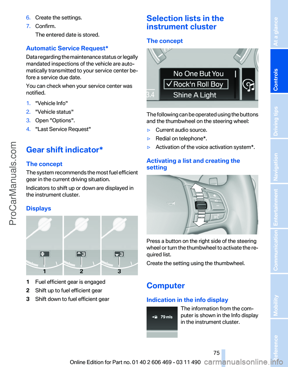
The
system recommends the most fuel efficient
gear in the current driving situation.
Indicators to shift up or down are displayed in
the instrument cluster.
Displays 1
Fuel efficient gear is engaged
2 Shift up to fuel efficient gear
3 Shift down to fuel efficient gear Selection lists in the
instrument cluster
The concept
The following can be operated using the buttons
and the thumbwheel on the steering wheel:
▷
Current audio source.
▷ Redial on telephone*.
▷ Activation of the voice activation system*.
Activating a list and creating the
setting Press a button on the right side of the steering
wheel
or turn the thumbwheel to activate the re‐
quired list.
Create the setting using the thumbwheel.
Computer
Indication in the info display
The information from the com‐
puter is shown in the Info display
in the instrument cluster. Seite 75
75Online Edition for Part no. 01 40 2 606 469 - 03 11 490
Reference Mobility Communication Entertainment Navigation Driving tips
Controls At a glance
ProCarManuals.com
Page 86 of 304
▷
Keep the dashboard and window on the
front
passenger side clear, i.e., do not cover
with adhesive labels or coverings, and do not
attach holders such as for navigation instru‐
ments and mobile phones.
▷ Make sure that the front passenger is sitting
correctly, i.e., keeps his or her feet and legs
in the footwell; otherwise, leg injuries can
occur if the front airbag is triggered.
▷ Do not place slip covers, seat cushions or
other objects on the front passenger seat
that are not approved specifically for seats
with integrated side airbags.
▷ Do not hang pieces of clothing, such as jack‐
ets, over the backrests.
▷ Make sure that occupants keep their heads
away from the side airbag and do not rest
against the head airbag; otherwise, injuries
can occur if the airbags are triggered.
▷ Do not remove the airbag restraint system.
▷ Do not remove the steering wheel.
▷ Do not apply adhesive materials to the air‐
bag cover panels, cover them or modify
them in any way.
▷ Never modify either the individual compo‐
nents
or the wiring in the airbag system. This
also applies to steering wheel covers, the
dashboard, the seats, the roof pillars and the
sides of the headliner.◀
Even when all instructions are followed closely,
injury from contact with the airbags cannot be
ruled out in certain situations.
The ignition and inflation noise may lead to
short-term
and, in most cases, temporary hear‐
ing impairment in sensitive individuals.
In the case of a malfunction, deactivation
and after triggering of the airbags
Do not touch the individual components imme‐
diately after the system has been triggered; oth‐
erwise, there is the danger of burns.
Only have the airbags checked, repaired or dis‐
mantled and the airbag generator scrapped by
your service center or a workshop that has the
necessary authorization for handling explosives. Non-professional attempts to service the sys‐
tem
could lead to failure in an emergency or un‐
desired triggering of the airbag, either of which
could result in injury.◀
Warnings and information on the airbags are
also found on the sun visors.
Functional readiness of the airbag
system
When the ignition is switch on, the warn‐
ing lamp in the instrument cluster lights
up briefly and thereby indicates the op‐
erational readiness of the entire airbag system
and the belt tensioner.
Airbag system malfunctioning
▷ In radio ready state, the warning lamp does
not come on.
▷ The warning lamp lights up continuously.
When there is a malfunction, have the air‐
bag system checked immediately
When there is a malfunction, have the airbag
system checked immediately; otherwise, there
is
a risk that the system does not function as ex‐
pected in the event of an accident despite cor‐
responding severity of the accident.◀
Automatic deactivation of the front
passenger airbags
The system determines whether the front pas‐
senger seat is occupied by measuring the re‐
sistance of the human body.
The front, knee, and side airbag on the front
passenger side are activated or deactivated ac‐
cordingly.
Leave feet in the footwell
Make sure that the front passenger keeps
his or her feet in the footwell; otherwise, the front
passenger airbags may not function properly.◀ Seite 86
86 Online Edition for Part no. 01 40 2 606 469 - 03 11 490
Safety
ProCarManuals.com
Page 89 of 304
For Canadian models: additional
information
The status display additionally shows the cur‐
rent tire inflation pressures and tire tempera‐
tures.
When correcting the tire inflation pressures,
note the following:
The tire pressure increases as the tire temper‐
ature increases.
Therefore, only correct the tire inflation pres‐
sure
when the tire is at the ambient temperature.
Compare the displayed tire temperature with
the external temperature in the instrument clus‐
ter.
Resetting the system
Reset the system after each correction of the
tire inflation pressure and after every tire or
wheel change.
1. "Vehicle Info"
2. "Vehicle status"
3. "Reset"
4. Start the engine - do not drive away.
5. Reset the tire pressure using "Reset".
6. Drive away.
The tires are shown in gray and "Resetting
TPM..." is displayed.
After
driving for a few minutes, the set tire infla‐
tion pressures are applied as set values. The re‐
setting process is completed automatically dur‐
ing driving. The tires are shown in green and
"TPM active" is shown on the Control Display.
The trip can be interrupted at any time. If you
drive away again, the process resumes auto‐
matically.
If a flat tire is detected during a reset, all tires are
displayed in yellow.
Low tire pressure message
The yellow warning lamp lights up. A
Check Control message is displayed.
▷There is a flat tire or a major loss in
tire inflation pressure. ▷
The system was not reset after a wheel
change and thus warns based on the infla‐
tion pressures initialized last.
1. Reduce your speed and stop cautiously.
Avoid sudden braking and steering maneu‐
vers.
2. Check whether the vehicle is fitted with reg‐
ular tires* or run-flat tires*.
Run-flat
tires, refer to page 252, are labeled
with a circular symbol containing the letters
RSC marked on the tire sidewall.
When a low inflation pressure is indicated, DSC
Dynamic
Stability Control is switched on if nec‐
essary.
Actions in the event of a flat tire
Normal tires*
1. Identify the damaged tire.
Do this by checking the air pressure in all
four tires.
If the tire inflation pressure in all four tires is
correct, the Tire Pressure Monitor may not
have been initialized. In this case, initialize
the system.
If an identification is not possible, please
contact the service center.
2. Rectify the flat tire.
Use
of tire sealant, e.g., the Mobility System,
may damage the TPM wheel electronics. In
this case, have the electronics checked at
the next opportunity and have them re‐
placed if necessary.
Run-flat tires*
You
can continue driving with a damaged tire at
speeds up to 50 mph/80 km/h.
Do not continue driving without run-flat
tires
Do not continue driving if the vehicle is not
equipped with run-flat tires; continued driving
may result in serious accidents.◀ Seite 89
89Online Edition for Part no. 01 40 2 606 469 - 03 11 490
Reference Mobility Communication Entertainment Navigation Driving tips
Controls At a glance
ProCarManuals.com
Page 90 of 304
Continued driving with a flat tire
If continuing to drive with a damaged tire:
1.
Avoid sudden braking and steering maneu‐
vers.
2. Do not exceed a speed of 50 mph/80 km/h.
3. Check the air pressure in all four tires at the
next opportunity.
If the tire inflation pressure in all four tires is
correct, the Tire Pressure Monitor may not
have been initialized. In this case, initialize
the system.
Possible driving distance with complete loss of
tire inflation pressure:
The possible driving distance after a loss of tire
inflation pressure depends on the cargo load
and the driving style and conditions.
For a vehicle containing an average load, the
possible driving distance is approx. 50 miles/
80 km.
When the vehicle is driven with a damaged tire,
its handling characteristics change, e.g., re‐
duced lane stability during braking, a longer
braking distance, and altered self-steering
properties. Adjust your driving style accord‐
ingly. Avoid abrupt steering maneuvers or driv‐
ing over obstacles, e.g., curbs, potholes, etc.
Because
the possible driving distance depends
on how the vehicle is used during the trip, the
actual distance may be smaller or greater de‐
pending on the driving speed, road conditions,
external temperature, cargo load, etc.
Continued driving with a flat tire
Drive moderately and do not exceed a
speed of 50 mph/80 km/h.
A loss of tire inflation pressure results in a
change in the handling characteristics, e.g., re‐
duced lane stability during braking, a longer
braking distance and altered self-steering prop‐
erties.◀
Final tire failure
Vibrations or loud noises while driving can
indicate the final failure of the tire. Reduce speed
and stop; otherwise, pieces of the tire could come loose and cause an accident. Do not con‐
tinue
driving, and contact your service center.◀
Message when the system was not
reset
A Check Control message is displayed.
The system detected a wheel change but was
not reset.
Warnings regarding the current tire inflation
pressure are not reliable.
Check the tire inflation pressure and reset the
system.
Malfunction The yellow warning lamp flashes and
then lights up continuously. A Check
Control message is displayed. No flat
tire can be detected.
Display in the following situations:
▷ A wheel without TPM electronics is fitted:
have
the service center check it if necessary.
▷ Malfunction: have the system checked by
your service center.
▷ TPM could not be fully reset. Reset the sys‐
tem again.
▷ Disturbance by systems or devices with the
same
radio frequency: after leaving the area
of the disturbance, the system automatically
becomes active again.
Declaration according to NHTSA/
FMVSS 138 Tire Pressure Monitoring
System
Each tire, including the spare (if provided)
should be checked monthly when cold and in‐
flated
to the inflation pressure recommended by
the vehicle manufacturer on the vehicle placard
or tire inflation pressure label. (If your vehicle has
tires of a different size than the size indicated on
the vehicle placard or tire inflation pressure la‐
bel, you should determine the proper tire infla‐
tion pressure for those tires.) As an added safety
feature, your vehicle has been equipped with a
tire pressure monitoring system (TPMS) that il‐
luminates a low tire pressure telltale when one Seite 90
90 Online Edition for Part no. 01 40 2 606 469 - 03 11 490
Safety
ProCarManuals.com
Page 125 of 304
Press the button.
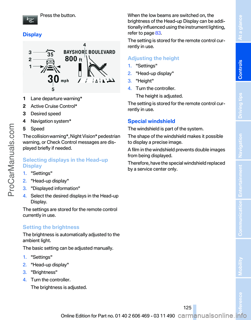
Display 1
Lane departure warning*
2 Active Cruise Control*
3 Desired speed
4 Navigation system*
5 Speed
The collision warning*, Night Vision* pedestrian
warning, or Check Control messages are dis‐
played briefly if needed.
Selecting displays in the Head-up
Display
1. "Settings"
2. "Head-up display"
3. "Displayed information"
4. Select the desired displays in the Head-up
Display.
The settings are stored for the remote control
currently in use.
Setting the brightness
The brightness is automatically adjusted to the
ambient light.
The basic setting can be adjusted manually.
1. "Settings"
2. "Head-up display"
3. "Brightness"
4. Turn the controller.
The brightness is adjusted. When the low beams are switched on, the
brightness
of the Head-up Display can be addi‐
tionally influenced using the instrument lighting,
refer to page 83.
The setting is stored for the remote control cur‐
rently in use.
Adjusting the height
1. "Settings"
2. "Head-up display"
3. "Height"
4. Turn the controller.
The height is adjusted.
The setting is stored for the remote control cur‐
rently in use.
Special windshield
The windshield is part of the system.
The shape of the windshield makes it possible
to display a precise image.
A
film in the windshield prevents double images
from being displayed.
Therefore, have the special windshield replaced
by a service center only.
Seite 125
125Online Edition for Part no. 01 40 2 606 469 - 03 11 490
Reference Mobility Communication Entertainment Navigation Driving tips
Controls At a glance
ProCarManuals.com
Page 132 of 304
Interior equipment
Integrated universal remote
control*
The concept
This system can replace up to three different
hand-held transmitters for various types of re‐
mote-controlled equipment, such as garage
doors or lighting systems.
The hand-held transmitter signal can be pro‐
grammed on one of the three memory buttons.
The
corresponding device can then be operated
using the programmed memory button.
The LED indicates that a signal is being trans‐
mitted.
When selling the vehicle, delete the stored pro‐
grams for security reasons.
During programming
During programming and before activat‐
ing a device using the universal remote control,
ensure that there are no people, animals, or ob‐
jects in the range of movement of the remote-
controlled device; otherwise, there is a risk of
injury or damage.
Also follow the safety instructions of the hand-
held transmitter.◀
Compatibility
If this symbol is printed on the packaging
or in the instructions of the hand-held
transmitter, the remote-controlled de‐
vice is generally compatible with the universal
remote control.
If you have any questions, please contact:
▷ Your service center.
▷ www.homelink.com on the Internet. Programming
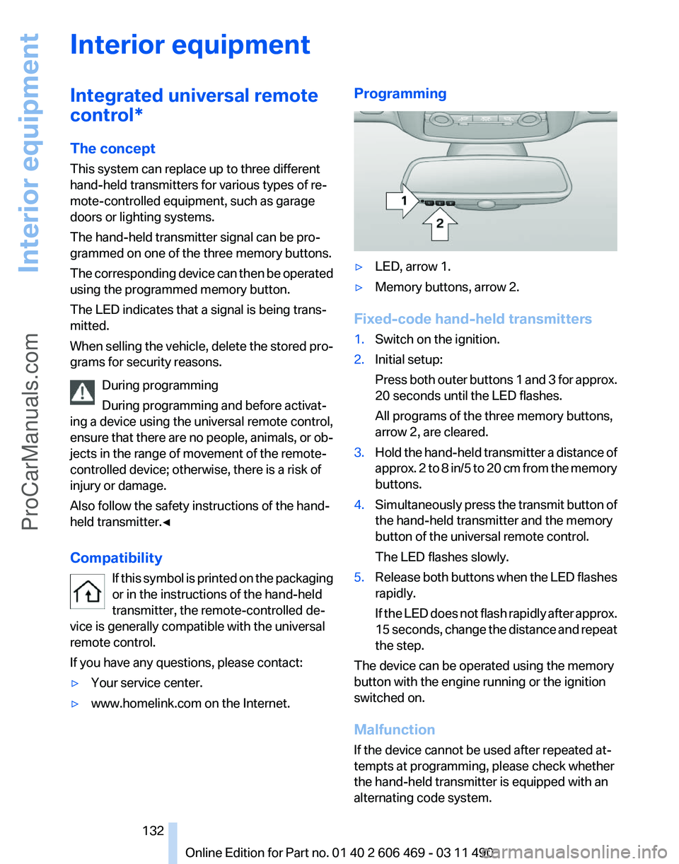
▷
LED, arrow 1.
▷ Memory buttons, arrow 2.
Fixed-code hand-held transmitters
1. Switch on the ignition.
2. Initial setup:
Press
both outer buttons 1 and 3 for approx.
20 seconds until the LED flashes.
All programs of the three memory buttons,
arrow 2, are cleared.
3. Hold the hand-held transmitter a distance of
approx.
2 to 8 in/5 to 20 cm from the memory
buttons.
4. Simultaneously press the transmit button of
the hand-held transmitter and the memory
button of the universal remote control.
The LED flashes slowly.
5. Release both buttons when the LED flashes
rapidly.
If
the LED does not flash rapidly after approx.
15 seconds, change the distance and repeat
the step.
The device can be operated using the memory
button with the engine running or the ignition
switched on.
Malfunction
If the device cannot be used after repeated at‐
tempts at programming, please check whether
the hand-held transmitter is equipped with an
alternating code system.
Seite 132
132 Online Edition for Part no. 01 40 2 606 469 - 03 11 490
Interior equipment
ProCarManuals.com
Page 137 of 304
Ensure that the lock is securely en‐
gaged
When
folding back the backrest, be sure that
it locks in place securely. If it is not properly
engaged, transported cargo could enter the
passenger compartment during braking or
evasive maneuvers and endanger the vehi‐
cle occupants.◀ 2.
Release the latch plate from the fixture on
the rear window shelf and insert it into the
belt
lock of the center safety belt. Make sure
you hear the latch plate engage.
To secure cargo, refer to page 149,
with nets or
draw straps, the cargo area is fitted with lashing
eyes.
Ski bag*
Capacity
The ski bag can be used to transport up to four
pairs of skis with a length of up to 6 ft/2.10 m or,
depending on the binding, up to two snow‐
boards with a length of up to 5 ft/1.60 m.
Preparing and loading the ski bag
1. Fold open the center armrest on the inside.
2. Open the inside cover and cargo area by
pressing the button. 3.
Lay out the ski bag.
4. Load the ski bag. If necessary, wrap the
sharp edges of the skis.
If
necessary, open the ski bag zipper to ease
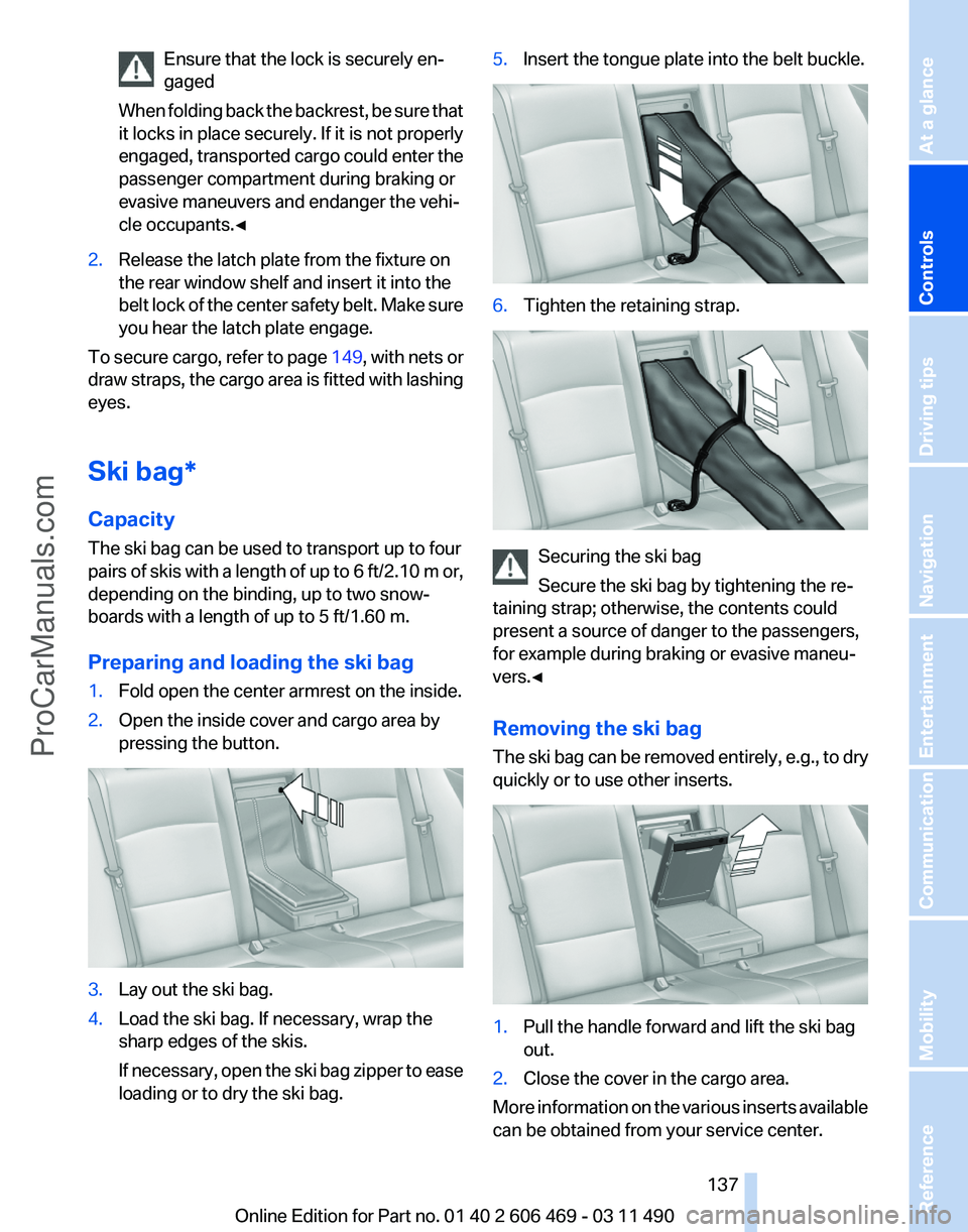
loading or to dry the ski bag. 5.
Insert the tongue plate into the belt buckle. 6.
Tighten the retaining strap. Securing the ski bag
Secure the ski bag by tightening the re‐
taining strap; otherwise, the contents could
present a source of danger to the passengers,
for example during braking or evasive maneu‐
vers.◀
Removing the ski bag
The
ski bag can be removed entirely, e.g., to dry
quickly or to use other inserts. 1.
Pull the handle forward and lift the ski bag
out.
2. Close the cover in the cargo area.
More information on the various inserts available
can be obtained from your service center. Seite 137
137Online Edition for Part no. 01 40 2 606 469 - 03 11 490
Reference Mobility Communication Entertainment Navigation Driving tips
Controls At a glance
ProCarManuals.com
Page 158 of 304
"Start search": if a search term is not entered,
the
search is repeated with the previous search
term.
Category search
1. "Category search"
2. "Town/City"
Select or enter the town/city.
3. "Category"
4. Select the category.
5. "Category details"
For
some special destinations, multiple cat‐
egory details can be selected. Move the
controller to the left to leave the category
details.
6. "Start search"
A
list of the special destinations is displayed.
7. Select a special destination.
Details are displayed.
If multiple details are stored, you can leaf
through the pages.
If
a phone number is available, a connection
can be established if necessary.
8. Select the symbol.
"Start guidance" or "Add as another
destination"
Add a destination as a further destination,
refer to page 160.
Display of special destinations
List
of special destinations: special destinations
are organized by distance and are displayed with
a directional arrow to the special destination.
on the split screen, special destinations of the
selected category are displayed in the map view
as symbols. The display depends on the scale
of the map and the category.
Destination entry via BMW Assist*
A connection is established to the Concierge
service, refer to page 233. 1.
"Navigation"
2. "Enter address"
3. Open "Options".
4. "BMW Assist dest. entry"
Displaying special destinations in the
map
To display symbols of the special destinations
in the map view:
1. "Navigation"
2. "Map"
3. Open "Options".
4. "Display Points of Interest"
5. Select the setting.
Destination entry by map
Selecting the destination
1. "Navigation"
2. "Map"
The current position of the vehicle is indi‐
cated on the map.
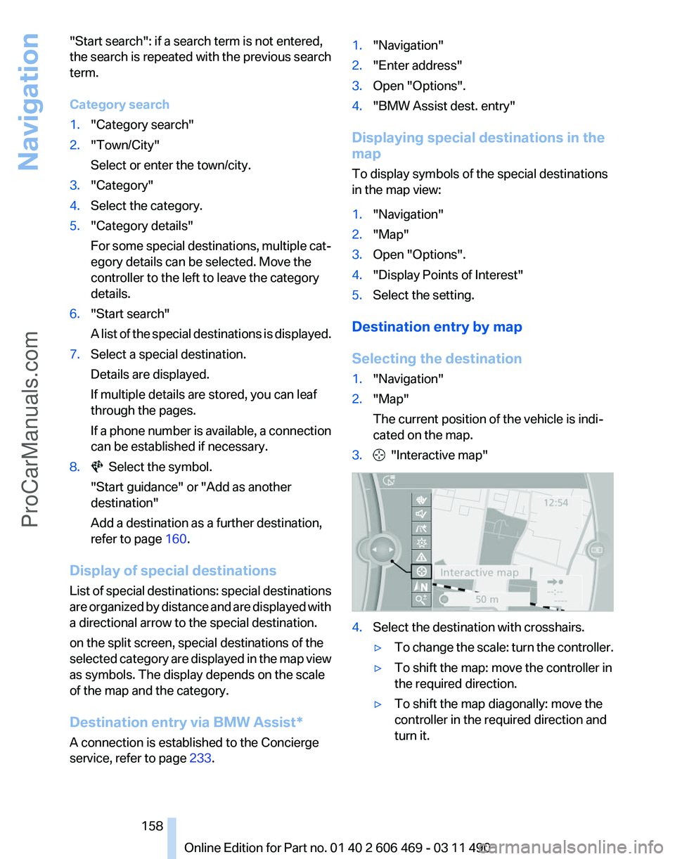
3. "Interactive map"
4.
Select the destination with crosshairs.
▷To change the scale: turn the controller.
▷ To shift the map: move the controller in
the required direction.
▷ To shift the map diagonally: move the
controller in the required direction and
turn it.
Seite 158
158 Online Edition for Part no. 01 40 2 606 469 - 03 11 490
Navigation
ProCarManuals.com
Page 165 of 304
Settings for the map view
The settings are stored for the remote control
currently in use.
1.
"Navigation"
2. "Map"
3. Open "Options".
4. "Settings"
Set the map view.
▷ "Day/night mode"
Select and create the necessary settings
depending on the light conditions.
"Traffic conditions/gray map" active: the
setting is disregarded.
▷ With the Professional navigation system:
"Satellite images"
Depending on availability and resolution,
satellite images* are displayed in a scale of
approx. 1 mile to 600 miles/2 km to
1,000 km.
▷ "Perspective view in 3D"
Prominent areas that are contained in the
navigation data are displayed on the map in
3D.
▷ "Traffic conditions/gray map"
The map is optimized for displaying traffic
bulletins,
refer to page 165. Symbols for the
special destinations are no longer displayed.
Map view for split screen
The map view can be selected for the split
screen independently from the main screen.
1. Open "Options".
2. "Split screen"
3. Move the controller to the right repeatedly
until the split screen is selected.
4. Select "Split screen content" or the scale.
5. Select the map view.
▷"Arrow display"
▷ "Map facing north"
▷ "Map direction of travel"
▷ "Map view with perspective" ▷
"Position"
▷ "Exit ramp view": selected blind drive‐
ways
are displayed three dimensionally.
Setting in some cases will affect the dis‐
play in the Head-Up Display*.
▷ "Traffic conditions/gray map"
6. To change the scale: select the split screen
and turn the controller.
Traffic bulletins*
At a glance
▷ Display the traffic bulletins from radio sta‐
tions that broadcast the TI Traffic Informa‐
tion
of a traffic information service. Informa‐
tion on traffic obstructions and hazards is
updated continuously.
Certain BMW models equipped with navi‐
gation have the capability to display real-
time traffic information. If your system has
this capability the following additional terms
and conditions apply:
An End-User shall no longer have the right
to use the Traffic Data in the event that the
End-User is in material breach of the terms
and conditions contained herein.
A. Total Traffic Network, a division of Clear
Channel Broadcasting, Inc. (“Total Traffic
Network”) holds the rights to the traffic in‐
cident data and RDS-TMC network through
which it is delivered. You may not modify,
copy, scan or use any other method to re‐
produce, duplicate, republish, transmit or
distribute in any way any portion of traffic in‐
cident data. You agree to indemnify, defend
and hold harmless BMW of North America,
LLC. (“BMW NA”) and Total Traffic Net‐
work, Inrix, Inc (and their affiliates) against
any and all claims, damages, costs or other
expenses that arise directly or indirectly out
of (a) your unauthorized use of the traffic in‐
cident data or the RDS-TMC network, (b)
your violation of this directive and/or (c) any
unauthorized or unlawful activities by you in
connection herewith.
Seite 165
165Online Edition for Part no. 01 40 2 606 469 - 03 11 490
Reference Mobility Communication Entertainment
Navigation Driving tips Controls At a glance
ProCarManuals.com
Page 167 of 304
in the map using triangles or gray bars along the
calculated route.
▷
Red: congestion.
▷ Orange: stop-and-go traffic.
▷ Yellow: heavy traffic.
▷ Green: clear roads.
▷ Gray: general traffic bulletins, e.g., construc‐
tion site.
The displayed information depends on the par‐
ticular traffic information service.
Filtering traffic bulletins
You
can set which traffic bulletins appear on the
map.
1. "Navigation"
2. "Map"
3. Open "Options".
4. "Traffic Info categories"
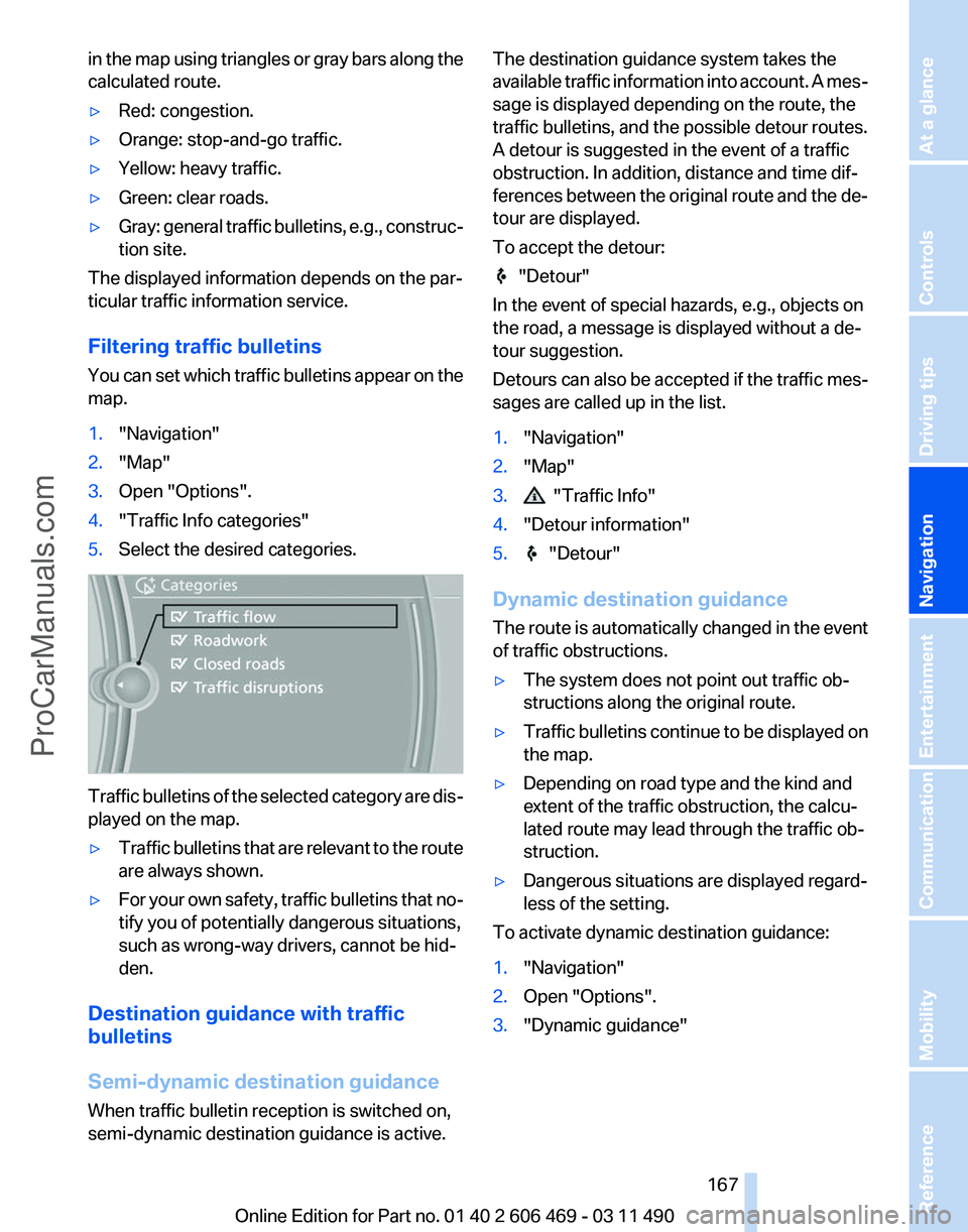
5. Select the desired categories. Traffic bulletins of the selected category are dis‐
played on the map.
▷
Traffic bulletins that are relevant to the route
are always shown.
▷ For your own safety, traffic bulletins that no‐
tify you of potentially dangerous situations,
such as wrong-way drivers, cannot be hid‐
den.
Destination guidance with traffic
bulletins
Semi-dynamic destination guidance
When traffic bulletin reception is switched on,
semi-dynamic destination guidance is active. The destination guidance system takes the
available
traffic information into account. A mes‐
sage is displayed depending on the route, the
traffic bulletins, and the possible detour routes.
A detour is suggested in the event of a traffic
obstruction. In addition, distance and time dif‐
ferences between the original route and the de‐
tour are displayed.
To accept the detour: "Detour"
In the event of special hazards, e.g., objects on
the road, a message is displayed without a de‐
tour suggestion.
Detours
can also be accepted if the traffic mes‐
sages are called up in the list.
1. "Navigation"
2. "Map"
3. "Traffic Info"
4. "Detour information"
5. "Detour"
Dynamic destination guidance
The
route is automatically changed in the event
of traffic obstructions.
▷ The system does not point out traffic ob‐
structions along the original route.
▷ Traffic bulletins continue to be displayed on
the map.
▷ Depending on road type and the kind and
extent of the traffic obstruction, the calcu‐
lated route may lead through the traffic ob‐
struction.
▷ Dangerous situations are displayed regard‐
less of the setting.
To activate dynamic destination guidance:
1. "Navigation"
2. Open "Options".
3. "Dynamic guidance"
Seite 167
167Online Edition for Part no. 01 40 2 606 469 - 03 11 490
Reference Mobility Communication Entertainment
Navigation Driving tips Controls At a glance
ProCarManuals.com