ECO BMW 525i 1997 E39 Workshop Manual
[x] Cancel search | Manufacturer: BMW, Model Year: 1997, Model line: 525i, Model: BMW 525i 1997 E39Pages: 1002
Page 924 of 1002
Downloaded from www.Manualslib.com manuals search engine
l Seats
Seat repair and component replacement is possible once the
seat has been removed from the vehicle.
Before servicing front seats read safety regulations on han-
dling
airbag modules and pyrotechnic seatbelt tensioners.
See
720 Seat belts and 721 Airbag system (SRS).
WARNING-
. The front seats are equipped with pyrotechnic seat belt
tensioners. These tensioners are powerful devices and
should be handled with exfreme care. Incorrect handling
can trigger off the tensioner and cause injury.
BMW recommends that all repair or replacement
worlc
on pyrotechnic devices must be carried out by a quali-
fied
BMW technician.
Be sure to disconnect the battery and wait
5 seconds
before attempting to work on pyrotechnic devices.
During body straightening and welding with an electric
arc welder, always disconnect the battery and the con-
nection to the pyrotechnic gas generators.
Seat switch and memory module, removing
and installing
- Remove front seat. See Front seats, removing and install-
ing.
- Carefully pull seat adjusting ltnobs straight out to remove.
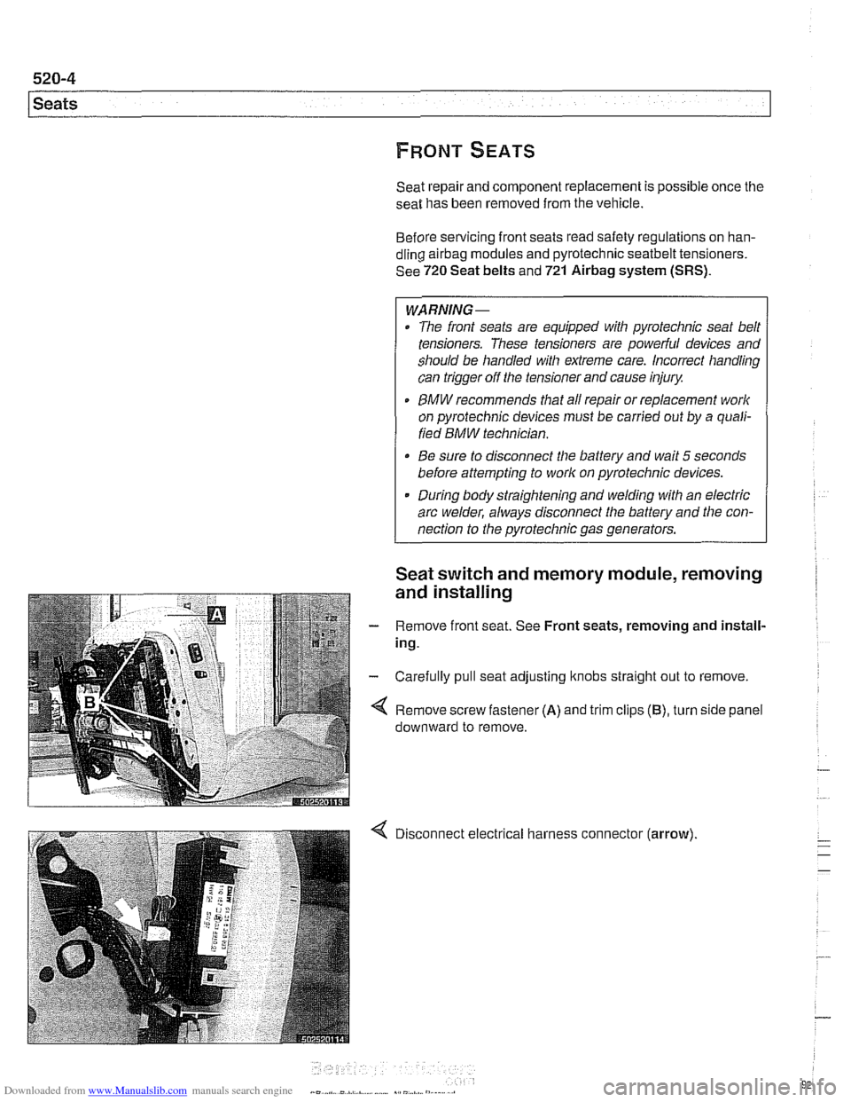
Remove screw fastener
(A) and trim clips (B), turn side panel
downward to remove.
Disconnect electrical harness connector
(arrow).
Page 931 of 1002
Downloaded from www.Manualslib.com manuals search engine
Sunroof, normalization
During normalization the mechanical end positions of sunroof
movement are detected and stored by the General Module
(GM
Ill).
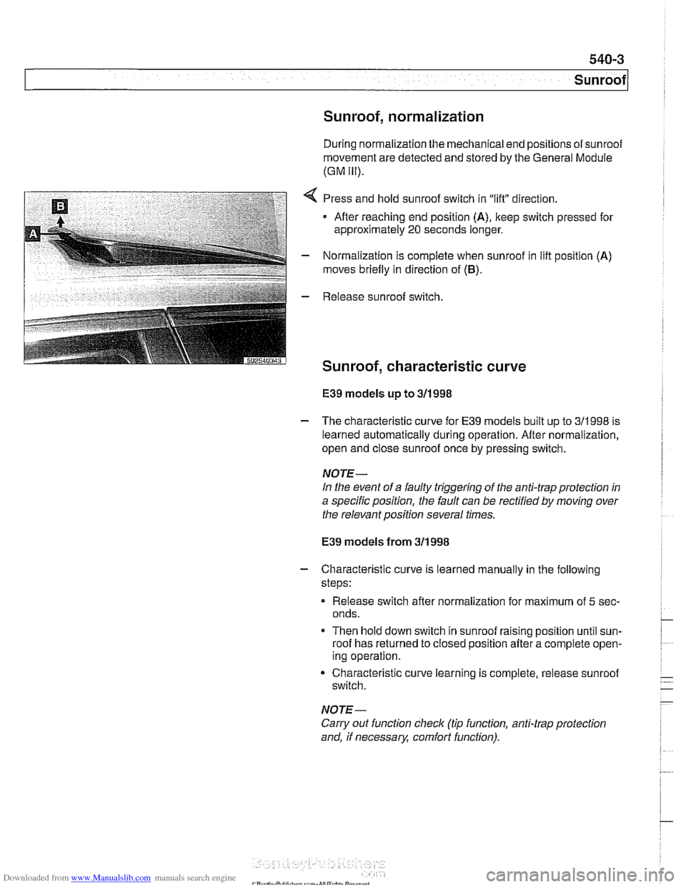
,:..I:,* *:3F$&-T , a,.,-. . 2 *i;.'I . :i_(,*,,_ _* Press and hold sunroof switch in "lift" direction.
Afler reaching end position
(A), keep switch pressed for
approximately
20 seconds longer.
- Normalization is complete when sunroof in lifl position (A)
moves briefly in direction of (6).
E39 models up to 311 998
- The characteristic curve for E39 models built up to 311998 is
learned automatically during operation. After normalization,
open and close sunroof once by pressing switch.
NOTE-
In the event of a faulty triggering of the anti-trap protection in
a specific position, the fault can be rectified
by moving over
the relevant position several times.
E39 models from 311 998
- Characteristic curve is learned manually in the following
steps:
Release switch after normalization for maximum of
5 sec-
onds.
Then hold down switch in sunroof raising position until sun-
roof has returned to closed position after a complete open-
ing operation.
Characteristic curve learning is complete, release sunroof
switch.
NOTE-
Carry out function check (tip function, anti-trap protection
and, if necessary, comfort function).
Page 942 of 1002
Downloaded from www.Manualslib.com manuals search engine
- -
Seat Belts
Front seat belt tensioner, removing and
installing
- Disconnect battery negative (-) cable in trunk.
The
front seat belt loclts are equipped with pyrotechnic (ex-
plosive charge) automatic tensioners. These tensioners are
designed to automatically retract and tension the seat belt by
55 mm (approximately 2 inches) in the event of an accident.
CAUTION-
Prior to disconnecting the battery, read the battery discon-
nection cautions given in
001 General Warnings and Cau-
tions.
WARNING-
Pyrotechnic seat belt tensioners are powerful devices and
should be handled with extreme care. Incorrect handling
can trigger the tensioner and cause injury
BMW recommends that all repair or replacement work
on pyrotechnic devices must be carried out by a quali-
fied BMW technician.
Be sure to disconnect the battery and wait
5 seconds
before attempting to work on pyrotechnic devices.
Pyrotechnic devices cannot be repaired. Always re-
place them.
Never treat pyrotechnic components with cleaning
agents or grease.
- Do not expose pyrotechnic components to tempera-
tures above
75% (167°F).
Pyrotechnic components can only be tested electrically
when installedusing the
BMWService Tester (DISplus,
GTI, or MoDiC).
Do not fire a pyrotechnic gas generatorprior to dispos-
al. It must be fired by a special disposal company or
shipped
back to BMW in the packaging of the new com-
ponent.
During body straightening and welding with an electric
arc welder, always disconnect the battery and the con-
nection to the pyrotechnic gas generators.
- Remove front seat as described in 520 Seats.
-
Page 953 of 1002
Downloaded from www.Manualslib.com manuals search engine
Airbag System (SRS)~
Warnings
When servicing airbag equipped cars, the following precau-
tions must be
observed to prevent personal injury.
WARNING-
. If the airbag indicator light is on, there is a risk that the air-
bags will not be triggered in case of an accident Be sure
to have the system inspected and repaired immediately
Airbag(s) are inflated by an explosive device. Handled
improperly or witliout adequate safeguards, the system
can be very dangerous. Special precautions must be
observed prior to any work at or near the airbags.
0 The airbag is a vehicle safety system. Serious injury
may result if system service is attempted by persons
unfamiliar with the BMW
MRS and its approved service
procedures. BMW advises that all inspection and ser-
vice be performed by an authorized BMW dealer.
Always disconnect the battery and cover the negative
(-) battery terminal with an insulator before starting di-
agnostic, troubleshooting or service
work not associat-
ed
with the airbags, and before doing any welding on
the car.
0 After disconnecting the battery, wait 5 seconds before
beginning work on
airbag components.
* If an airbag has been activated due to an accident,
BMW specifies that
airbag components be replaced.
For more information on post-collision
airbag service,
see an authorized BMW dealer.
Do not fire an
airbag unit prior to disposal. It must be
fired by a special disposal company or shipped back to
BMW in the packaging of the new components.
When removing a fired
airbag unit, avoid contact with
the
skin; weargloves. In case ofskin contact, wash with
water.
Do not allow
airbag system components to come in
contact with cleaning solutions or grease. Never sub-
ject
airbag components to temperatures above 167°F
(75°C). When reconnecting the battery, no person
should be inside the vehicle.
Always place an
airbag unit that has been removed
from its
packaging with the paddedside facing upward.
Do not leave an
airbag unit unattended.
0 If the airbag unit or airbag control module has been
dropped from a height of
'/? meter (I//: ft.) or more, the
airbag unit should not be installed.
Page 956 of 1002
Downloaded from www.Manualslib.com manuals search engine
721 -8
(Airbag System (SRS)
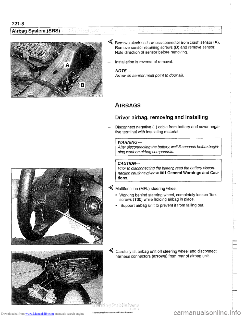
4 Remove electrical harness connector from crash sensor (A).
Remove sensor retaining screws (6) and remove sensor.
Note direction of sensor before removing.
- Installation is reverse of removal,
NOTE -
Arrow on sensor must point to door sill.
Driver airbag, removing and installing
- Disconnect negative (-) cable from battery and cover nega-
tive terminal with insulating material.
WARNING-
After disconnecting the batter)! wait 5 seconds before begin-
ning work on
airbag components.
CAUTION-
Prior to disconnecting the batter)! read the battery discon-
nection cautionsgiven
in001 General Warnings and Cau-
tions.
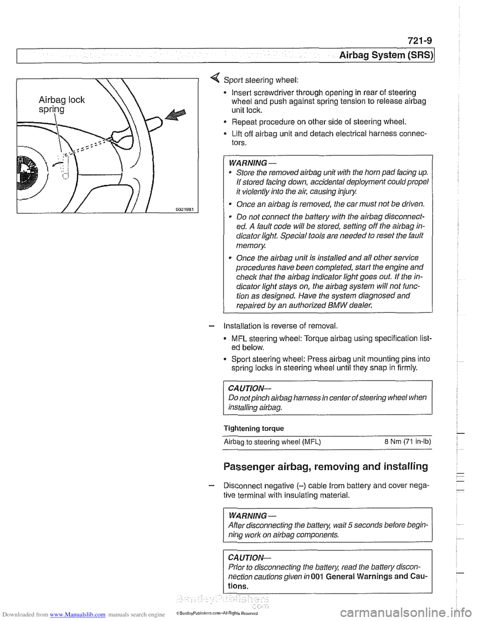
4 Multifunction (MFL) steering wheel:
. Working behind steering wheel, completely loosen Torx
screws
(T30) while holding airbag in place.
Support
airbag unit to prevent it from falling out.
Page 957 of 1002
Downloaded from www.Manualslib.com manuals search engine
721 -9
Airbaq System ~SRS)~
4 Sport steering wheel:
Insert screwdriver through opening in rear of steering
wheel and push against spring tension to release
airbag
unit lock.
Repeat procedure on other side of steering wheel.
Lift off
airbag unit and detach electrical harness connec-
tors.
WARNING-
Store the removedairbag unit with the horn pad facing up.
If stored facing down, accidental deployment could propel
it violently into the air, causing injury.
Once an
airbag is removed, the car must not be driven.
Do not connect the battery with the
airbag disconnect-
ed. A fault code will be stored, setting off the
airbag in-
dicator light Special tools are needed to reset the fault
memory
Once the
airbag unit is installed and all other service
procedures have been completed, start the engine and
check that the
airbag indicator light goes out. If the in-
dicator light stays on, the
airbag system will not func-
tion as designed. Have the system diagnosed and
repaired by an authorized
BMW dealer.
- Installation is reverse of removal.
MFL steering wheel: Torque airbag using specification list-
ed below.
- Sport steering wheel: Press airbag unit mounting pins into
spring
loclts in steering wheel until they snap in firmly.
CAUTION--
Do notpinch airbag harness in center of steering wheel when
installino
airbaa.
Tightening torque
Airbao to steerino wheel IMFL) 8 Nm (71 in-lb)
Passenger airbag, removing and installing
- Disconnect negative (-) cable from battery and cover nega-
tive terminal with insulating material.
--
WARNING -
After disconnecting the batteg wait 5 seconds before begin-
nina work on airbaa components.
Prior to disconnecting the battery, read the battery discon-
nection cautionsgiven in001 General Warnings and
Cau-
Page 961 of 1002
Downloaded from www.Manualslib.com manuals search engine
OBD On-Board Diagnostics
I I
General ........................... OBD-1 Diaqnostic Trouble Codes (DTCs) . . OBD-9
On-Board Diagnostics (OBD I!) ..... OBD-I
Malfunction Indicator Light (MIL)
........ OBD-2
Scan tools and scan tool display.
........ OBD-3
Diagnostic monitors
.................. OED-4
Drive cycle
......................... OED-6
Readiness codes
.................... OBD-6
Diagnostic trouble codes
(DTCs) ........ OBD-7
-
Automatic transmission diagnostic
trouble codes
....................... OBD-9
Engine diagnostic trouble
codes: M52 engine.
................. OED-13
Engine diagnostic trouble
codes: M54 engine.
................. OBD-17
Engine diagnostic trouble
codes: M62 engine.
................. OBD-24
This chapter outlines the fundamentals and equipment
requirements of On-Board Diagnostics
I1 (OBD 11) standards
as they apply to BMW vehicles. Also covered here is a listing
of BMW and OBD
I1 diagnostic trouble codes (DTCs).
ON-BOARD DIAGNOSTICS (QBD !I)
OBD II standards were developed by the SAE (Society of
Automotive Engineers) and CARB (California Air Resources
Board).
OED I1 is the second generation of on-board self-
diagnostic equipment requirements. These standards were
originally mandated for California vehicles. Since
1996 they
have been applied
toall passengervehicles sold in the United
States.
On-board diagnostic capabilities are incorporated into the
hardware and soflwareof the enginecontrol module
(ECM) to
monitor virtually every component that can affect vehicle
emissions. The
OED I1 system works to ensure that
emissions remain as clean as possible over the life of the
vehicle.
Each emission-influencing component is checked by a
diagnostic routine (called a monitor) to verify that it is
functioning properly.
If a problem or malfunction is detected,
the
diagnostic executive built into the OBD I1 system
illuminates a malfunction indicator light (MIL) on the
instrument panel.
The OBD
I1 system also stores diagnostic trouble codes
(DTCs) about the detected malfunction in the ECM so that a
repair technician can accurately find and fix the problem.
Page 963 of 1002
Downloaded from www.Manualslib.com manuals search engine
OBD-3
On-Board
~iactnosticsl
Additional MIL information:
A fault code is stored within the ECM upon the first
occurrence of a fault in the system being checlted.
Two complete consecutive drive cycles with the iault
present illuminate the MIL. The exception to the two-fault
requirement is a catalyst-damaging fault, which illuminates
the MIL immediately.
If the second drive cycle was not complete and the fault
was not checked, the ECM counts the third drive cycle as
the next consecutive drive cycle. The MIL illuminates
if the
system is checked and the fault is still present.
Once the MIL is illuminated, it remains illuminated until the
vehicle completes three consecutive drive cycles without
detecting a fault.
0 An existing fault code is cleared from memory
automatically when the vehicle completes
40 consecutive
drive cycles without the fault being detected.
In order to automatically clear a catalyst-damaging fault from
memory, the condition underwhich the fault occurred must be
evaluated for 80 consecutive drive cycles without the fault
reoccurring.
A generic scan tool connected to the BMW data link
connector (DLC) or OBD
I1 plug can display diagnostic trouble
codes (DTCs), along with the conditions associated with the
illumination of the MIL. Using a more advanced or
BMW-
dedicated scan tool, additional proprietary information is
normally available.
Scan tool and scan tool display
The complexity of the OBD I1 system requires that all
diagnostics begin by connecting a scan tool to the vehicle.
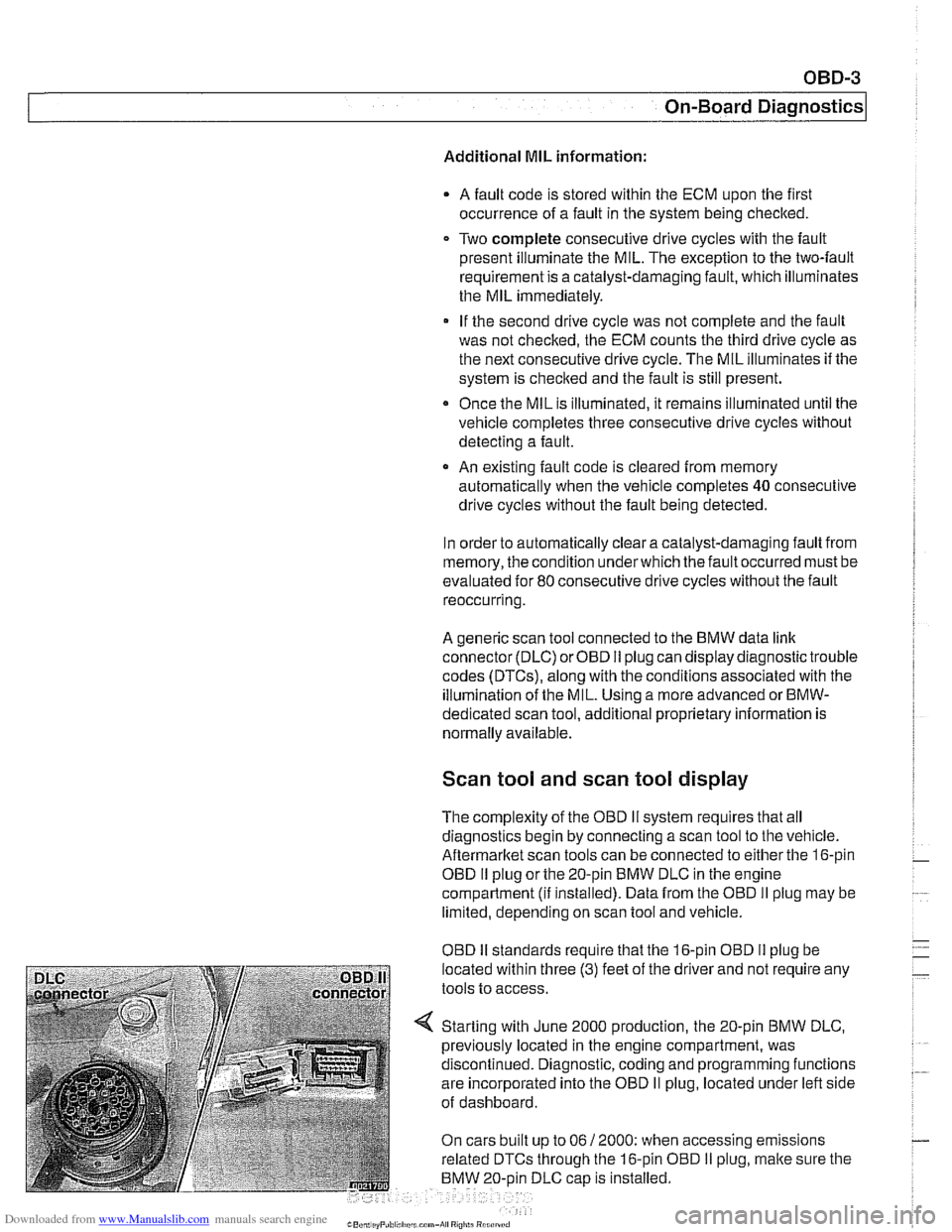
Aftermarltet scan tools can be connected to either the 16-pin
OBD
I1 plug or the 20-pin BMW DLC in the engine
compartment
(ii installed). Data from the OBD II plug may be
limited, depending on scan tool and vehicle.
OBD
I1 standards reouire that the 16-oin OBD I1 oluo be
located within three
(3) feet of the driier and not're&ire any
tools to access.
Starting with June 2000 production, the 20-pin BMW DLC,
previously located in the engine compartment, was
discontinued. Diagnostic, coding and programming functions
are incorporated into the OBD
II plug, located under left side
of dashboard.
On cars built up to 06
/ 2000: when accessing emissions
related DTCs through the 16-pin OBD
I1 plug, malte sure the
BMW 20-oin DLC
caD is installed.
Page 964 of 1002
Downloaded from www.Manualslib.com manuals search engine
- -
On-Board Diagnostics
Professional diagnostic scan tools available atthe time of this
printing include the BMW factory tools
(DISplus, GTI,
MoDiC) and a small number of aftermarket BMW-specific
tools. See
020 Maintenance.
In addition to the professional line of scan tools, inexpensive
generic OBD
II scan tool software programs and handheld
units are readily available. Though limited, they are
nonetheless powerful diagnostic tools. These tools read live
data streams and freeze frame data as well as a host of other
valuable diagnostic data.
Diagnostic monitors
Diagnostic monitors run tests and checks on specific
emission control systems, components, and functions.
A complete drive cycle is requiredforthe tests to bevalid. See
Drive cycle in this repair group. The diagnostic monitor
signals the
ECM of the loss or impairment of the signal or
component and determines if a signal or sensor is faulty
based on
3 conditions:
* Signal or component shorted to ground
Signal or component shorted to
B+
Signal or component missing (open circuit)
The OBD
II system monitors all emission control systems that
are installed. Emission control systems vary by vehicle model
and year. For example, a vehicle may not be equipped with
secondary air injection, so no secondary air readiness code
would be present.
OBD
II software monitors the following:
Oxygen sensors
Catalysts
Engine misfire
- Fuel tank evaporative control system
Secondary air injection Fuel system
Oxygen sensor monitoring. When driving conditions allow,
response rate and switching time of each oxygen sensor is
monitored. The oxygen sensor heater function is also
monitored. The OBD
II system differentiates between
precataylst and post-catalyst oxygen sensors and reads each
one individually. In order
forthe oxygen sensor to be
effectively monitored, the system must be in closed loop
operation.
Page 965 of 1002
Downloaded from www.Manualslib.com manuals search engine
On-Board Diagnostics
Catalyst monitoring. Thisstrategy monitors the outputofthe
precatalyst and post-catalyst oxygen sensors, comparing the
oxygen content going into the catalytic converter to the
oxygen leaving the converter.
The diagnostic executive
lknows that most of the oxygen
should be used up during the oxidation phase. If it detects
higherthan programmed values, afault is set and the MIL
illuminates.
Misfire detection. This strategy monitors crankshaft speed
fluctuations and determines if an enoine misfire occurs bv
monitoring variations in speed between each crankshaft
sensortrigger point. This strategy is so finely tuned that it can
determine the severity of the misfire.
The system determines
if a misfire is occurring, as well as
other pertinent misfire
information such as:
Specific
cylinder(s)
Severity of the misfire event
Emissions relevant or catalyst damaging
Misfire detection is an on-going monitoring process that is
only disabled under certain limited conditions.
Secondary air injection monitoring. Secondary air
injection is used to reduce HC and CO emissions during
engine warm up. Immediately following a cold engine start
(-1 0" to 40°C), fresh air (and therefore oxygen) is pumped
directly into the exhaust
manifold. By injecting additional
oxygen into the exhaust manifold, catalyst warm-up time is
reduced.
Secondary air system components are:
Electric air injection pump
* Electric pump relay
* Non-return valve
Vacuum
I vent valve
- Stainless steel air injection pipes
Vacuum reservoir
The secondary air system is monitored via the use
of the pre-
catalyst oxygen sensors. Once the air pump is active and air
is injected into the system, the signal at the oxygen sensor
reflects a lean condition. If the oxygen sensor signal does not
change, a fault is set and the faulty
bank(s) identified. If after
completing the next cold startafault is again present, the MIL
illuminates.