ECO BMW 525i 1997 E39 Workshop Manual
[x] Cancel search | Manufacturer: BMW, Model Year: 1997, Model line: 525i, Model: BMW 525i 1997 E39Pages: 1002
Page 898 of 1002
Downloaded from www.Manualslib.com manuals search engine
51 5-4
I Central Locking and Anti-Theft
Driver's door lock
The
lock/unlock signals are sent as input to the door module
from two microswitches on the lockcylinder. The driver's door
module carries out the locking
/ unlocking functions of the
driver's door through its final stage control.
The signal to lock the remaining doors, trunk or tailgate and
fuel flap is sent over the P-Bus to the GM and the passenger
door module. Activation of the passengers door
loclt is carried
out by the passenger door module. The rear doors, trunlt or
tailgate and fuel flap are
locked by the f~nal stage in the GM.
When
locked from the outside, all doors are set to the double
lock position and the GM will not carry out any unlock com-
mands from the central
loclc button or remote trunk release
button.
Selective unlocking
When unlocking with the key or the remote transmitter, the
first unloclcrequestwill only unlock the driver'sdoor. A second
unlock request will unlock the remaining doors, trunk or tail-
gate and fuel flap.
Trunk locking
I
The vehicle can be locked/unlocked from the trunlc loclc cylin-
der. The GM locks the trunk or tailgate, rear doors and fuel fill-
er. The locking command is passed over the P-Bus to the
respective door modules to lock the driver's and passengers
doors.
Locking the trunk and removing the key in the
hor~zontal posi-
tion will set the valet lock and prevent opening of the trunlt
with the central locking system.
Central locking switch
-
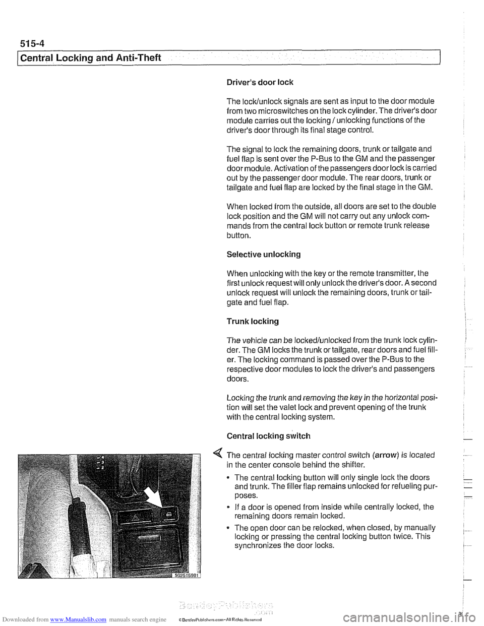
< The central locking master control switch (arrow) is located
in the center console behind the shifter.
The central locking button will only single
loclt the doors
and trunk. The filler flap remains unloclted for refueling pur-
poses.
If a door is opened from inside while centrally locked, the
remaining doors remain locked.
The open door can be relocked, when closed, by manually
locking or pressing the central locking button twice. This
synchronizes the door
locks.
Page 903 of 1002
Downloaded from www.Manualslib.com manuals search engine
515-9
Central Locking and ~nti-~heftl
FZV keys
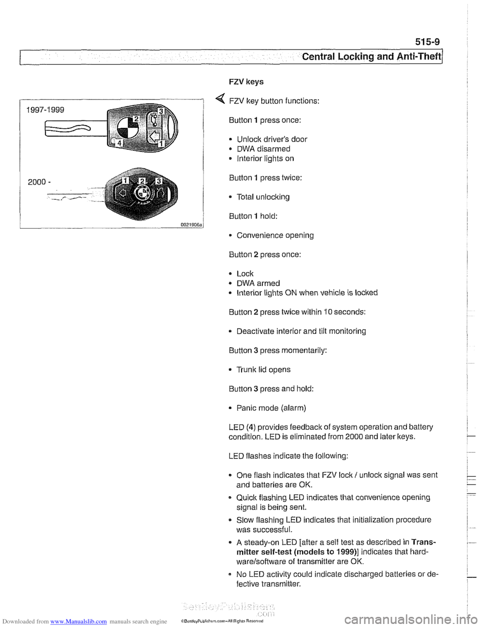
4 FZV key button functions:
Bunon 1 press once:
Unlock driver's door
DWA disarmed
/ lnterior lights on
... - 0021~0~~j
Convenience opening
2000
-
'.-,- /- ..,.
Button 2 press
once:
Button
1 press twice:
a Total
unlocking
Button
1 hold:
* Lock
- DWA armed
lnterior lights ON when vehicle is locked
Button
2 press twice within 10 seconds:
Deactivate interior and tilt monitoring
Button 3 press momentarily:
Trunk lid opens
Button
3 press and hold:
Panic mode (alarm)
LED
(4) provides feedback of system operation and battery
condition. LED is eliminated from 2000 and later
lkeys.
LED flashes indicate the following:
One flash indicates that FZV
lock I unlock signal was sent
and batteries are OK.
Quick flashing LED indicates that convenience opening
signal is being sent.
Slow flashing LED indicates that initialization procedure
was successful.
A steady-on LED [after a self test as described in Trans-
mitter self-test (models to
1999)l indicates that hard-
warelsoftware of transminer are OK.
No LED activity could indicate discharged batteries or de-
fective
transmitter.
Page 904 of 1002
Downloaded from www.Manualslib.com manuals search engine
1 Central Locking and Anti-Theft
NOJE-
A single unlock request from the driver's door with the FZV
key unlocks the driver's door only.
A second unlock request
unlocls the remaining doors and trunk. This feature can be
modified for individual users with the Key Memory capabil-
ities to activate all lock actuators simultaneously See Car
Memory
/ Key Memory later in this section.
Starting with 2000 models, the battery in the FZV ignition
Icey is recharged by the ignition switch ring antenna while
the ley is in the ignition switch.
Transmitter self-test (models to
1999)
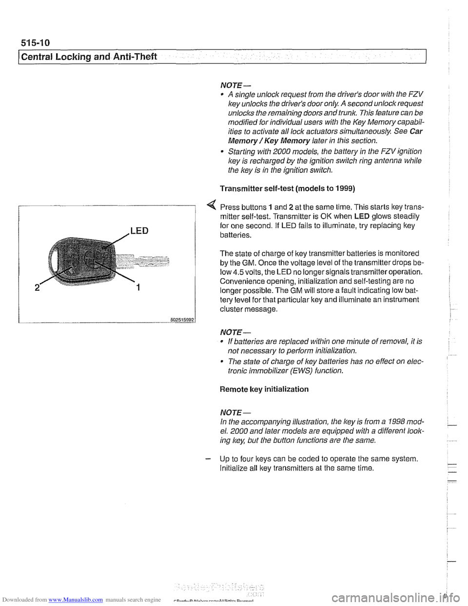
Press buttons 1 and 2 at the same time. This starts ltey trans-
/ mitter self-test. Transmitter is OK when LED glows steadily
te{le"el for that particular key and illuminate an instrument
cluster message.
-- 502515092 J
NO JE-
If batteries are replaced within one minute of removal, it is
not necessary to
periorm initialization.
Tlie state of charge of key batteries has no effect on elec-
tronic immobilizer (EWS) function.
2
Remote key initialization
for one second. If LED fails to illuminate, try replacing ltey~
batteries.
The state of charge of key transmitter batteries is monitored
by the
GM. Once the voltage level of the transmitter drops be-
low
4.5volts, the LED no longersignals transmitteroperation.
Convenience opening, initialization and self-testing are no
lonaer ~ossible. The GM will store a fault indicatina low bat-
NOJE-
In the accompanying illustration, the key is from a 1998 mod-
el. 2000 and later models are equipped with a different look-
ing
/
Initialize all key transmitters at the same time.
Page 905 of 1002
Downloaded from www.Manualslib.com manuals search engine
515-11
Central Lockinq and ~nti-l heft/
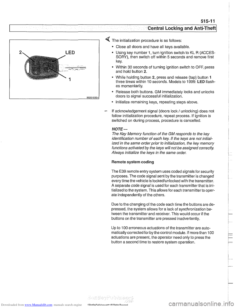
4 The initialization procedure is as follows:
Close ail doors and have all keys available
2 LED Using lkey number I, turn ignition switch to KL R (ACCES-
SORY), then switch off within 5 seconds and remove first
key.
. - -- , ..-.---- - Within 30 seconds of turning ignition switch to OFF, press
and hold button
2.
1 While holding button 2, press and release (tap) button 1
three times within 10 seconds. Models to 1999: LED flash-
- If acknowledgement signal (doors lock / unlocking) does not
follow initialization procedure, repeat process. If ignition is
switched on during process, procedure is cancelled.
50251509‘1
NOTE-
The Key Memory function of the GM responds to the ley
identification number of each key If the keys are not initial-
ized
in the same orderprior to initialization, the ley memory
functions activated by the
l(eys will not be assigned correctly.
Always initialize the keys
in the same order.
es momentarily.
Release both buttons. GM immediately locks and unlocits
doors to signal successful initialization.
Remote system coding
* Initialize remaining lteys, repeating steps above.
The E39 remote entry system uses coded signals for security
purposes. The code signal sent by the transmitter is changed
every time the vehicle is lockedlunlocked with the transmitter.
A separate code signal is used for each transmitter that is ini-
tialized to the system. This allows for each transmitterto oper-
ate independently of the others.
Due to the changing of the code each time the buttons are de-
pressed, the system allows for a
lacit of synchronization be-
tween the transmitter and receiver. This would occur
if the
buttons on the transmitter are pressed inadvertently.
Up to
100 erroneous actuations of the transmitter are auto-
matically corrected
forby the control module. If more than 100
actuations are present, the operator need only to press the
button a second time to restore system operation.
Page 906 of 1002
Downloaded from www.Manualslib.com manuals search engine
51 5-12
I Central Locking and Anti-Theft
Key battery
9
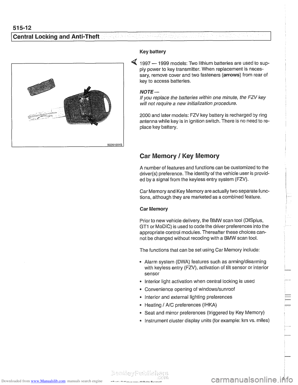
4 1997 - 1999 models: Two lithium batteries are used to sup-
ply power to key transmitter. When replacement is neces-
sary, remove cover and two fasteners (arrows) from rear of
key to access batteries
NOTE-
If you replace the batteries within one minute, the FZV ley
will not require a new initialization procedure.
2000 and later models: FZV key battery is recharged by ring
antenna while ltey is in ignition switch. There is no need to re-
place ltey battery.
Car Memory 1 Key Memory
A number of features and functions can be customized to the
driver(s) preference. The identity of the vehicle user is provid-
ed by a
s~gnal from the keyless entry system (FZV).
Car Memory and Key Memory are actually two separate func-
tions, although they are marketed as a combined feature.
Car Memory
Pr'or ro new
veh c,e de very, the BMW scan roo (DISp us,
GTI or MOD C) is ~sed lo cooc ine driver preierences nro ine
appropriate control modules. Thereafter these choices can-
not be changed without
recoding with a BMW scan tool.
The functions that can be set using Car Memory include:
Alarm system (DWA) features such as armingldisarming
with
lkeyless entry (FZV), activation of tilt sensor or interior
sensor
lnterior light activation when central
locking is used
Convenience opening of
windows/sunroof
lnterior and external lighting preferences
Heating
I A/C preferences (IHKA)
Seat and mirror preferences (triggered by Key Memory)
Instrument cluster display units (for example: km vs. miles)
Page 908 of 1002
Downloaded from www.Manualslib.com manuals search engine
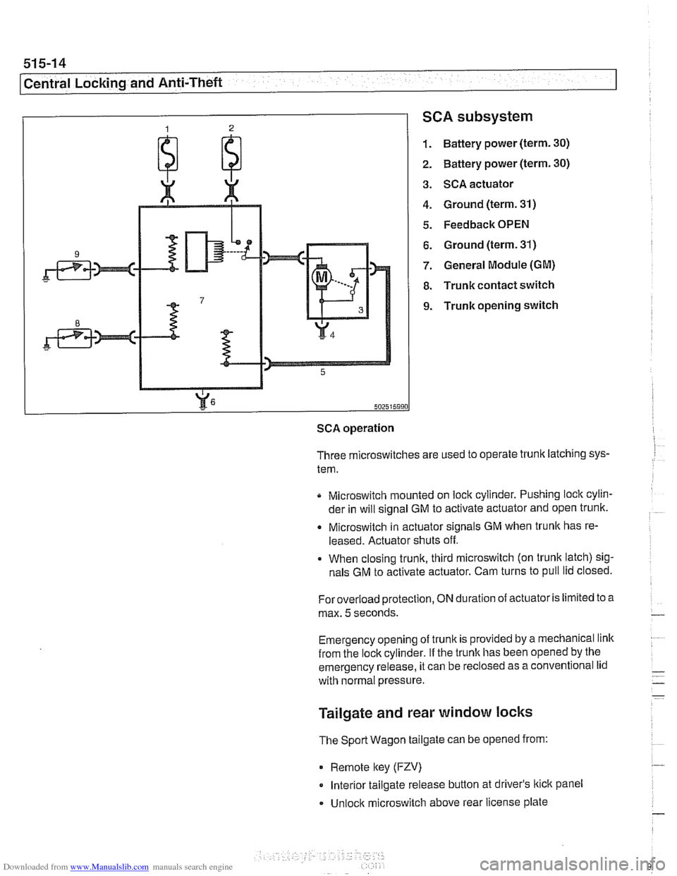
SCA subsystem
1. Battery power (term. 30)
2. Battery power (term. 30)
3. SCA actuator
4. Ground (term. 31)
5. Feedback OPEN
6. Ground (term. 31)
7. General Module (GM)
8. Trunk contact switch
9. Trunk opening switch
502515990
SCA operation
Three microswitches are used to operate trunk latching sys-
tem.
Microswitch mounted on lock cylinder. Pushing lock cylin-
der in will signal GM to activate actuator and open trunk.
Q Microswitch in actuator signals GM when trunlc has re-
leased. Actuator shuts off.
When closing trunk, third microswitch (on trunk latch) sig-
nals GM to activate actuator. Cam turns to pull lid closed.
Foroverload protection,
ON duration of actuator is limited to a
max.
5 seconds.
Emergency opening of trunk is provided by a mechanical link
from the lockcylinder.
If the trunlc has been opened by the
emergency release, it can be
reclosed as a conventional lid
with normal pressure.
Tailgate and rear window locks
The Sport Wagon tailgate can be opened from:
0 Remote lkey (FZV)
Interior tailgate release button at driver's lkick panel
Unlock microswitch above rear license plate
Page 918 of 1002
Downloaded from www.Manualslib.com manuals search engine
51 5-24
l~entral Locking and Anti-Theft
ANTI-THEFT SYSTEM (DWA)
When the anti-then system (DWA) is armed, the doors, hood,
windows, trunk lid or tailgate are monitored against forcible
entry by switches and sensors. The vehicle is protected
against being jacked up or towed away by a tilt sensor.
The control electronics for DWA are integrated in the General
Module (GM). In addition to the control electronics, the sys-
tem includes the following components.
* DWA horn
DWA LED indicator
- Tilt sensor
- Monitoring switches and sensors
The system can be armed or disarmed from the driver's door
lock,
trunklid lock, tailgate lockorthe remote transmitter (FZV
Itey). When armed, the alarm horn
soundsfor30seconds and
the low beam headlights and turn signals flash for
5 minutes.
The electronic immobilizer (EWS) is also activated when
DWA is activated.
The alarm is switched off immediately if key is inserted in door
loclt or FZV key button is used.
DWA LED Status
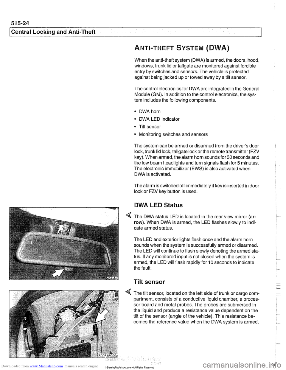
The DWA status LED is located in the rear view mirror (ar-
row). When DWA is armed, the LED flashes slowly to indi-
cate armed status.
The LED and exterior lights flash once and the alarm horn
sounds when the system is successfully armed ordisarmed.
The LED will continue to flash slowly denoting the armed sta-
tus. If any monitored input is not closed when the system is
armed, the LED will flash rapidly for
10 seconds to indicate
the fault.
Tilt sensor
-
4 The tilt sensor, located on the left side of trunlt or cargo com- -
partment, consists of a conductive liquid chamber, a proces-
sor board and metal probes. The probes are submersed in
the liquid and produce a resistance value dependent on the
tilt of the sensor (angle of the vehicle). This resistance be-
comes the reference value when the DWA system is armed.
.-
Page 919 of 1002
Downloaded from www.Manualslib.com manuals search engine
51 5-25
Central Lockina and ~nti-~heftl
1
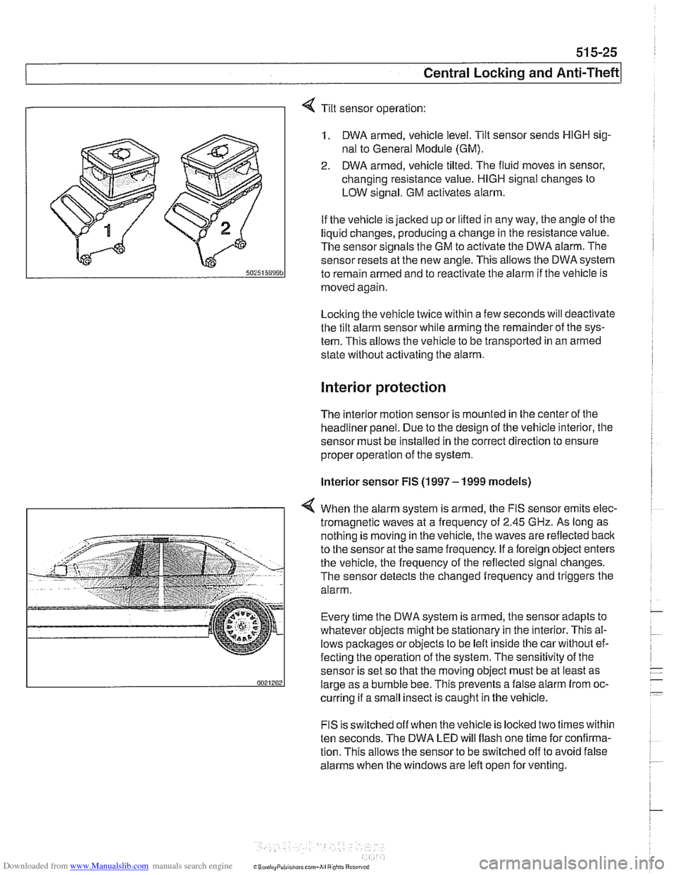
Tilt sensor operation:
1. DWA armed, vehicle level. Tilt sensor sends HlGH sig-
nal to General Module (GM).
2. DWA armed, vehicle tilted. The fluid moves in sensor,
changing resistance value.
HlGH signal changes to
LOW signal. GM activates alarm.
If the vehicle is jacked up or lifted in any way, the angle of the
liquid changes, producing a change in the resistance value.
The sensor signals the GM to activate the DWA alarm. The
sensor resets at the new angle.
This allows the DWA system
to remain armed and to reactivate the alarm if tlie vehicle is
moved again
Locking the vehicle twice within a few seconds will deactivate
the tilt alarm sensor while arming tlie remainder of the sys-
tem. This allows the vehicle to be transported in an armed
state without activating tlie alarm.
Interior protection
The interior motion sensor is mounted in the center of the
headliner panel. Due to the design of the vehicle interior, the
sensor must be installed in the correct direction to ensure
proper operation of the system.
lnterior sensor FIS (1997 - 1999 models)
4 When the alarm system is armed, the FIS sensor emits elec-
tromagnetic waves at
a frequency of 2.45 GHz. As long as
nothing is moving in the vehicle, the waves are reflected
baclc
to the sensor at the same frequency. If a foreign object enters
the vehicle, the frequency of the reflected signal changes.
The sensor detects the changed frequency and triggers the
alarm.
Every time the DWA system is armed, the sensor adapts to
whatever objects might be stationary in the interior. This al-
lows pacltages or objects to be left inside tlie car without ef-
fecting the operation of the system. The sensitivity of the
sensor is set so that the moving object must be at least as
large as a bumble bee. This prevents a false alarm from oc-
curring if a small insect is caught in the vehicle.
FIS is switched off when the vehicle is locked two times within
ten seconds. The DWA LED will flash one time for confirma-
tion. This allows the sensor to be switched off to avoid false
alarms when the windows are left open for venting.
Page 920 of 1002
Downloaded from www.Manualslib.com manuals search engine
51 5-26
Central Locking and Anti-Theft
Interior sensor UIS (2000 and later models)
The
UIS system uses ultrasonic sound waves instead of elec-
tromagnetic waves. Ultrasonic sound waves are less suscep-
tible to magnetic interference.
Every time the DWA system is armed, the sensor adapts to
whatever objects might be stationary in the interior. The sen-
sor emits ultrasonic waves in a programmed timed cycle. It re-
ceives echoes of the emitted waves. The
UIS amplifies the
received sound wave signals and compares them to the ech-
oes of the transmitted waves. The
UIS also checits the incom-
ing echoes for background hiss (wind noise through a
partially open window) and adapts for this.
If the echoes are consistently similar, no movement is de-
tected.
If the echoes are altered, (inconsistent), the UIS deter-
mines motion in the interior compartment.
If motion is detected, the
UIS changes to a constant cycle
and the echo is compared again.
If the inconsistency is still present the
UIS sends the acti-
vate siren signal to the GM.
Glass breakage sensors
The doorwindows are monitored by inductive sensors mount-
ed on the inside of the door behind the trim panel. A closed
window is recognized by a magnetic plate
on the glass lining
up with the sensor. If the glass is broken, the plate falls away
and the signal from the sensor changes. This causes the GM
to activate the alarm.
Emergency disarming
- An emergency procedure is provided to cancel the DWA in
the event that a fault occurs within the system. The procedure
is as follows:
Driver's door mechanically
unloclted and open within 30
seconds. This will cause triggering of alarm.
All doors closed.
Ignition switch turned to
KL R (ACCESSORY). LED indica-
tor will come on.
- After 10 minutes, alarm is disarmed
Page 922 of 1002
Downloaded from www.Manualslib.com manuals search engine
l Seats
This repair group covers removal and installation of the front
and rear seat.
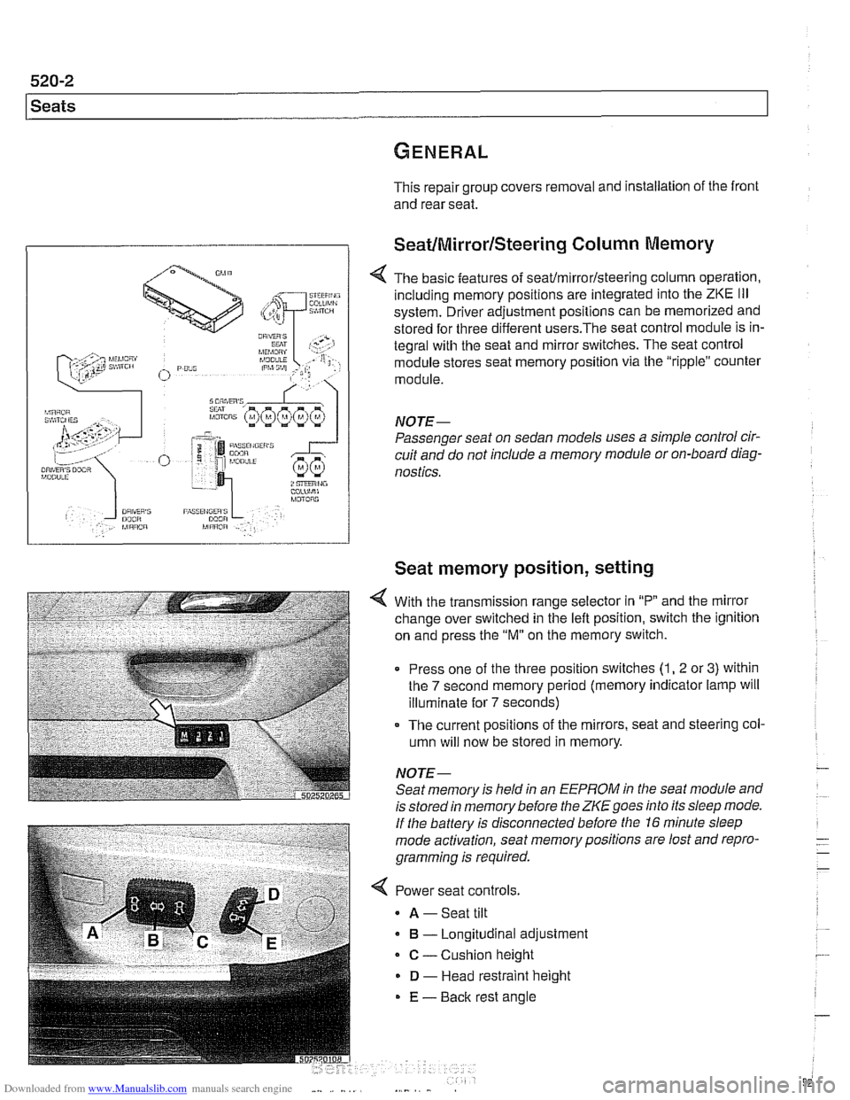
SeatIMirrorlSteering Column Memory
< The basic features of seaffmirrorlsteering column operation,
including memory positions are integrated into the
ZKE Ill
system. Driver adjustment positions can be memorized and
stored for three different
users.The seat control module is in-
tegral with the seat and mirror switches. The seat control
module stores seat memory position via the "ripple" counter
module.
NOTE-
Passenger seat on sedan models uses a simple control cir-
cuit and do not include a memory module or on-board diag-
nostics.
Seat memory position, setting
With the transmission range selector in "P and the mirror
change over switched in the left position, switch the ignition
on and press the
"M" on the memory switch.
Press one of the three position switches
(1, 2 or 3) within
the
7 second memory period (memory indicator lamp will
illuminate for
7 seconds)
- The current positions of the mirrors, seat and steering col-
umn will now be stored in memory.
NOTE- Seat memory is held in an
EEPROM in the seat module and
is stored in memory before the
ZKE goes into its sleep mode.
If the battery is disconnected before the 16 minute sleep
mode activation, seat memorypositions are lost and repro-
gramming is required.
< Power seat controls.
A -Seat tilt
B - Longitudinal adjustment
C - Cushion height
D - Head restraint height
E - Back rest angle