ECO BMW 525i 1997 E39 Workshop Manual
[x] Cancel search | Manufacturer: BMW, Model Year: 1997, Model line: 525i, Model: BMW 525i 1997 E39Pages: 1002
Page 678 of 1002
Downloaded from www.Manualslib.com manuals search engine
/steering and Wheel Alignment
Raise engine approximately 40 mm (1.6 in). See 110 Engine
Removal and installation.
Remove right and left engine mounts and remove mount
brackets from subframe.
Empty power steering fluid reservoir using a clean syringe.
Do not reuse power steering fluid.
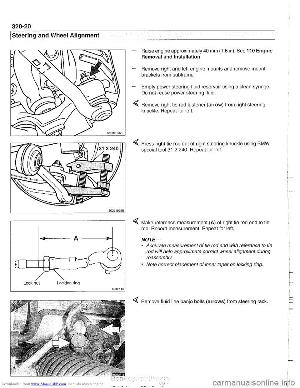
Remove right tie rod fastener (arrow) from right steering
Itnuckle. Repeat for left.
4 Press right tie rod out of right steering knucltle using BMW
special tool 31
2 240. Repeat for left.
/ ~ock nut Loclting ring
0012143
4 Malte reference measurement (A) of right tie rod end to tie
rod. Record measurement. Repeat for left.
NOJE-
0 Accurate measurement of tie rod end with reference to tie
rod will help approximate correct wheel alignment during
reassembly.
Note correct placement of inner taper on
locling ring
Remove fluid line
banjo bolts (arrows)
from steering rack.
Page 680 of 1002
Downloaded from www.Manualslib.com manuals search engine
--. --
Steering and Wheel Alignment
Steering rack boot, replacing
- Remove outer tie rod end. See Tie rod (outer), replacing
- Cut rack boot band clamps and remove boot.
- Cut rack boot band clamp and slide bellows back. Inspect
boot for any sign of damage. Replace
if necessary.
NOTE-
New rack boot lit comes with new band clamp.
- Grease tie rod taper so that small end of rack boot slides on
tie rod when tie rod is tightened, preventing raclc boot from
twisting.
- Slide new boot into position and replace band clamps
Tie rod (outer), replacing
LOCI( nut Locking ring
- Raise front of car. Remove road wheel
WARNING-
Male sure caris firmly suppoiiedon jackstands designed for
the purpose. Place jack stands beneath structural chassis
ooints. Do not olace iack stands under
susoension oaiis.
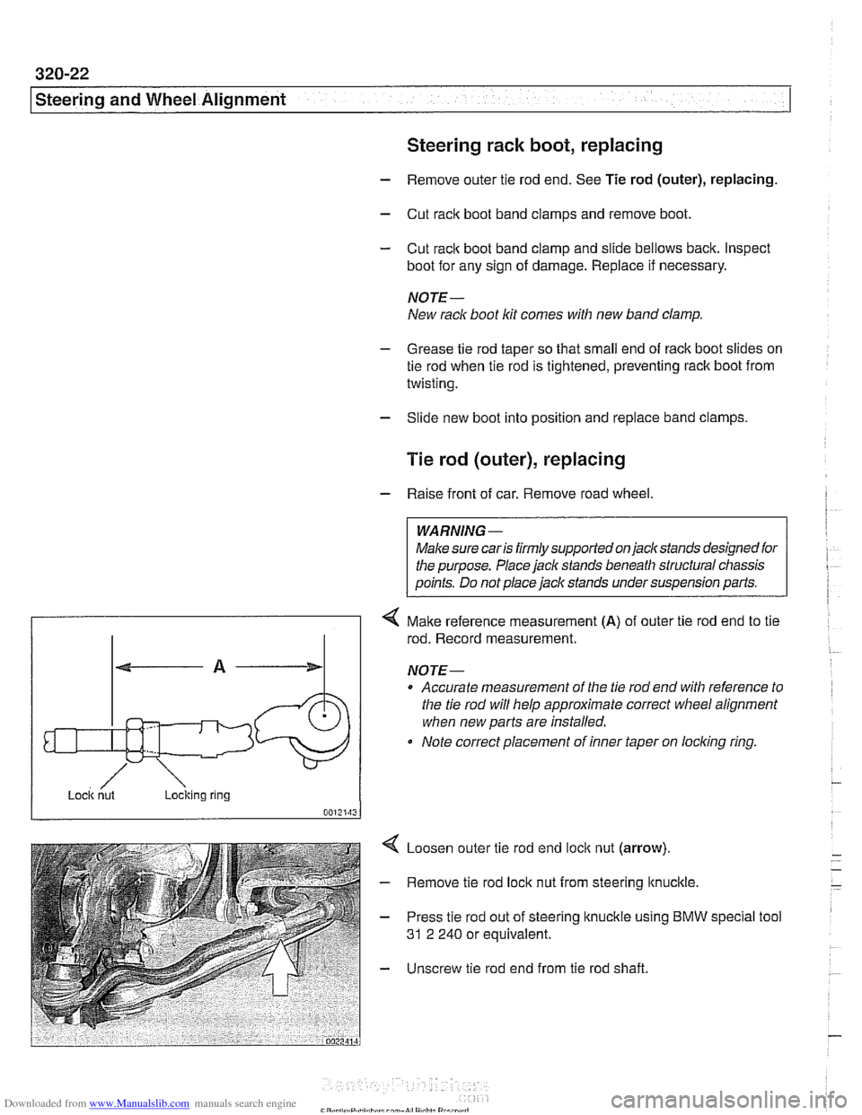
4 Make reference measurement (A) of outer tie rod end to tie
rod. Record measurement.
NOTE-
Accurate measurement of the tie rod end with reference to
the tie rod will help approximate correct
wheel alignment
when new parts are installed.
Note correct placement of inner taper on
loclcing ring.
Loosen outer tie rod end
loclc nut (arrow).
Remove tie rod lock nut from steering
ltnuclcle.
Press tie rod out of steering knuckle using BMW
31 2 240 or equivalent. special tool
Unscrew tie rod end from tie rod shaft.
Page 685 of 1002
Downloaded from www.Manualslib.com manuals search engine
L.. Steering and Wheel ~li~nrnentl ~
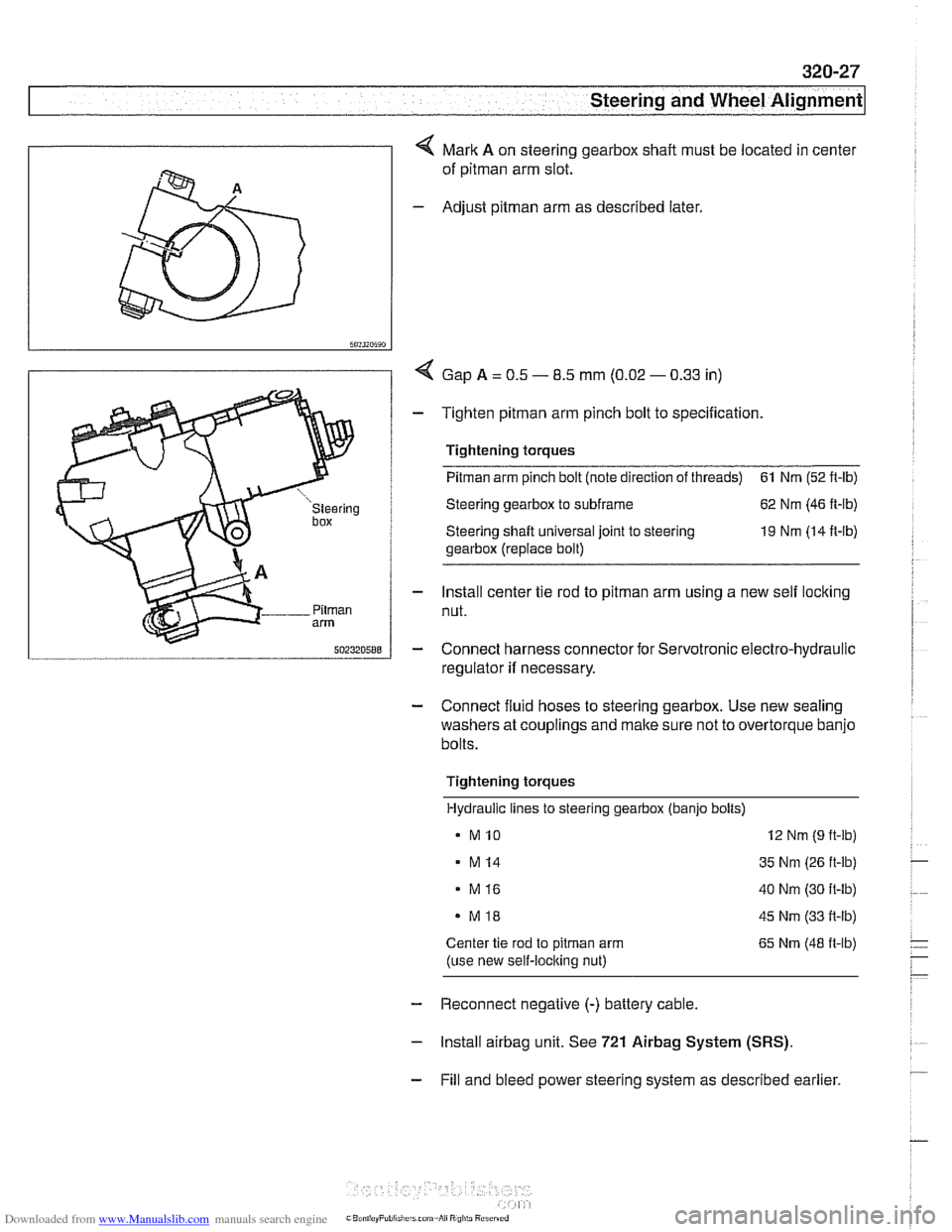
4 Mark A on steering gearbox shaft must be located in center
of
pitman arm slot.
- Adjust pitman arm as described later.
I 5"?~~5~"
I / < Gap A = 0.5 - 8.5 mm (0.02 - 0.33 in)
- Tighten pitman arm pinch bolt to specification.
' 1 Tightening torques
I u "steering Steering gearbox to subframe 62 Nm (46 ft-lb)
box Steering shaft universal joint to steering 19 Nm (14 It-lb)
gearbox (replace bolt)
- Install center tie rod to pitman arm using a new self locking
Pilrnan nut. arm
5nz3zn588 - Connect harness connector for Servotronic electro-hydraulic
regulator
if necessary.
- Connect fluid hoses to steering gearbox. Use new sealing
washers at couplings and make sure not to overtorque banjo
bolts.
Tightening torques Hydraulic lines to steering gearbox (banjo bolts)
MI0 12 Nm (9 ft-lb)
- M14 35 Nm (26 ft-lb)
. M16 40 Nm (30 ft-lb)
MI8 45 Nm (33 it-lb)
Center tie rod to pitrnan arm 65 Nm (48 it-lb)
(use new self-loclting nut)
- Reconnect negative (-) battery cable.
- lnstall airbag unit. See 721 Airbag System (SRS).
- Fill and bleed power steering system as described earlier.
Page 692 of 1002
Downloaded from www.Manualslib.com manuals search engine
320-34
I Steerins and Wheel Alignment
Front toe and toe difference angle
Toe is the difference in the distance between the front of the
front wheels and the rear of the front wheels. It is adjusted by
altering the length of the tie rods.
Toe difference angle determines the progressively different
paths taken by the front wheels as the car is turning. In
V-8
models, it is set by the pitman arm adjustment, but depends
on accurate setting of the toe.
Toe adjustments should only be made on specialized align-
ment equipment and only with the car in normal loaded posi-
tion, described below.
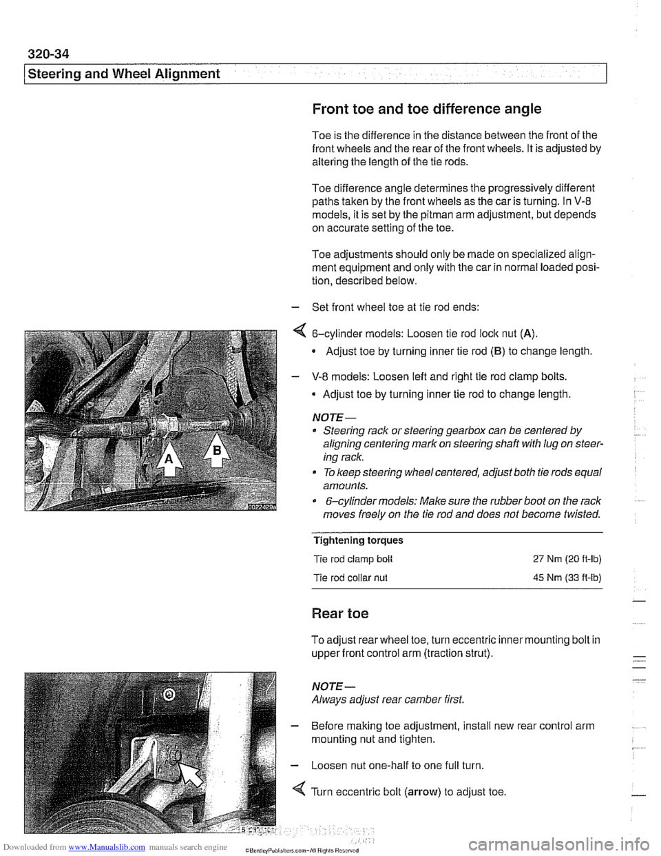
- Set front wheel toe at tie rod ends:
4 6-cylinder models: Loosen tie rod lock nut (A).
Adjust toe by turning inner tie rod (B) to change length
- V-8 models: Loosen left and right tie rod clamp bolts.
Adjust toe by turning inner tie rod to change length.
NOTE-
* Steering rack or steering gearbox can be centered by
aligning centering mark on steering shaft
with lug on steer-
ing rack.
To keep steering wheel centered, adjust both tie rods equal
amounts.
&cylinder models: Make sure the rubber boot on the rack
moves freely on the tie rod and does not become twisted.
Tightening torques
Tie rod clamp bolt
Tie rod collar
nut
27 Nm (20 ft-lb)
45 Nm (33 A-lb)
Rear toe
To adjust rear wheel toe, turn eccentric inner mounting bolt in
upper front control arm (traction strut).
NOTE-
Always adjust rear camber first.
- Before making toe adjustment, install new
mounting nut and tighten.
- Loosen nut one-half to one full turn.
4 Turn eccentric bolt (arrow) to adjust toe. rear
control arm
Page 727 of 1002
Downloaded from www.Manualslib.com manuals search engine
Rear Suspension
- Remainder of installation is reverse of removal, noting the fol-
lowing.
Tighten suspension arm and shock absorber fasteners to
final torque only afler vehicle has been lowered and sus-
pension has settled.
Tightening torques
ABS pulse sensor to wheel bearing carrier 8
Nrn (6 ft-lb)
Air line connection 2 Nrn (18 in-lb)
Brake rotor to hub 16
Nrn (12 ft-lb)
Driveshaft
CV joint to final drive flange
- MI0 (Torx bolts) 70
Nrn (51 ft-lb)
- MB (compression nut) 32 Nrn (24 ft-lb)
Rear
brake pad carrier (caliper) to wheel 65
Nrn (48 ft-lb)
bearing carrier
Road wheel to hub
120ilO Nrn
(89 i-7 ft-lb)
Rear subframe mounting bushings,
removing and installing
- Remove rear subframe mounting bolts as described earlier.
Lower
subframe approximately 40 - 45 mm (1 -2 in).
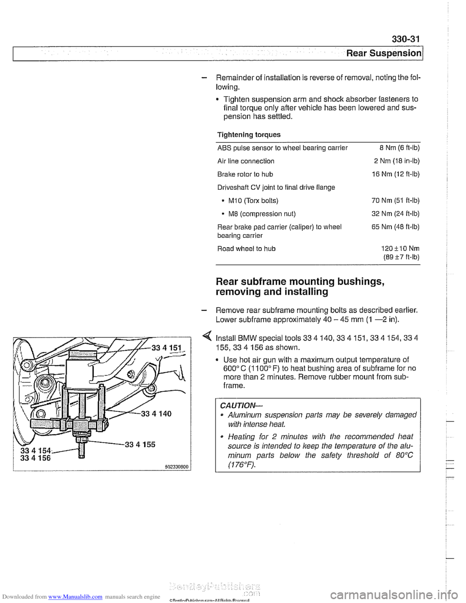
4 Install BMW special tools 33 4 140,33 4 151,33 4 154,33 4
155,33 4 156 as shown.
Use hot air gun with a maximum output temperature of
600°C (1100" F) to heat bushing area of subframe for no
more than
2 minutes. Remove rubber mount from sub-
frame.
CAUTION-
Aluminum suspension parts may be severely damaged
witli intense heat
* Heating for 2 minutes with the recommended heat
source is intended to
keep the temperature of the alu-
minum
parts below the safety threshold of 80°C
(1 76°F). .
Page 746 of 1002
Downloaded from www.Manualslib.com manuals search engine
331-2
Final Drive
This repair group covers removal and repair informat~on for
the final drive (differential), axle shafts.
CV joints, CV joint
boots, and final drive seal replacement.
Internal repairs of the differential assembly are not covered in
this manual.
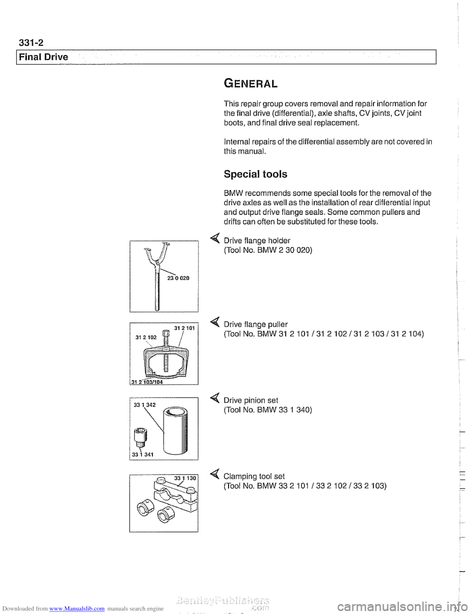
Special tools
BMW recommends some special tools for the removal of the
drive axles as well as the installation of rear differential input
and output drive flange seals. Some common pullers and
drifts can often be substituted for these tools.
4 Drive flange holder
(Tool No. BMW
2 30 020)
< Drive flange puller
(ToolNo.BMW31 2101 131 2102131 2103131 2104)
< Drive pinion set
(Tool No. BMW 33 1 340)
4 Clamp~ng tool set
(ToolNo.BMW332101 13321021332103)
Page 750 of 1002
Downloaded from www.Manualslib.com manuals search engine
Final Drive
Tightening torques
F~nal drive to rear axle carrier 105 Nm (77 it-lb)
Driveshaft CV joint to final drive flange
- MlO (Torx bolt) 70
Nm (51 ft-lb)
- M8 (compression nut) 32 Nm (24
ft-lb)
Drive axle to final drive
ilange
Torx bolts (M10) 83 Nm (61 ft-lb)
Torx bolt with
rlbbed teeth (M10) 64 Nm (47 ft-lb)
Torx bolt
wlth ribbed teeth (MI0 sliver) 80 Nm (59 ft-lb)
Torx
bolt with ribbed teeth (M10 black) 100 Nm (74 ft-lb)
* Torx bolt with ribbed teeth (M12) 135 Nm (100 ft-lb)
Differential oil level, checking
The E39 differential is filled with lifetime oil that ordinarily
does not need to be changed. BMW recommends using only
a specially formulated synthetic gear oil
(SAF-XO) that is
available through an authorized BMW dealer parts depart-
ment. For additional information on this lubricant and any oth-
er lubricants that may be compatible, contact an authorized
BMW dealer service department.
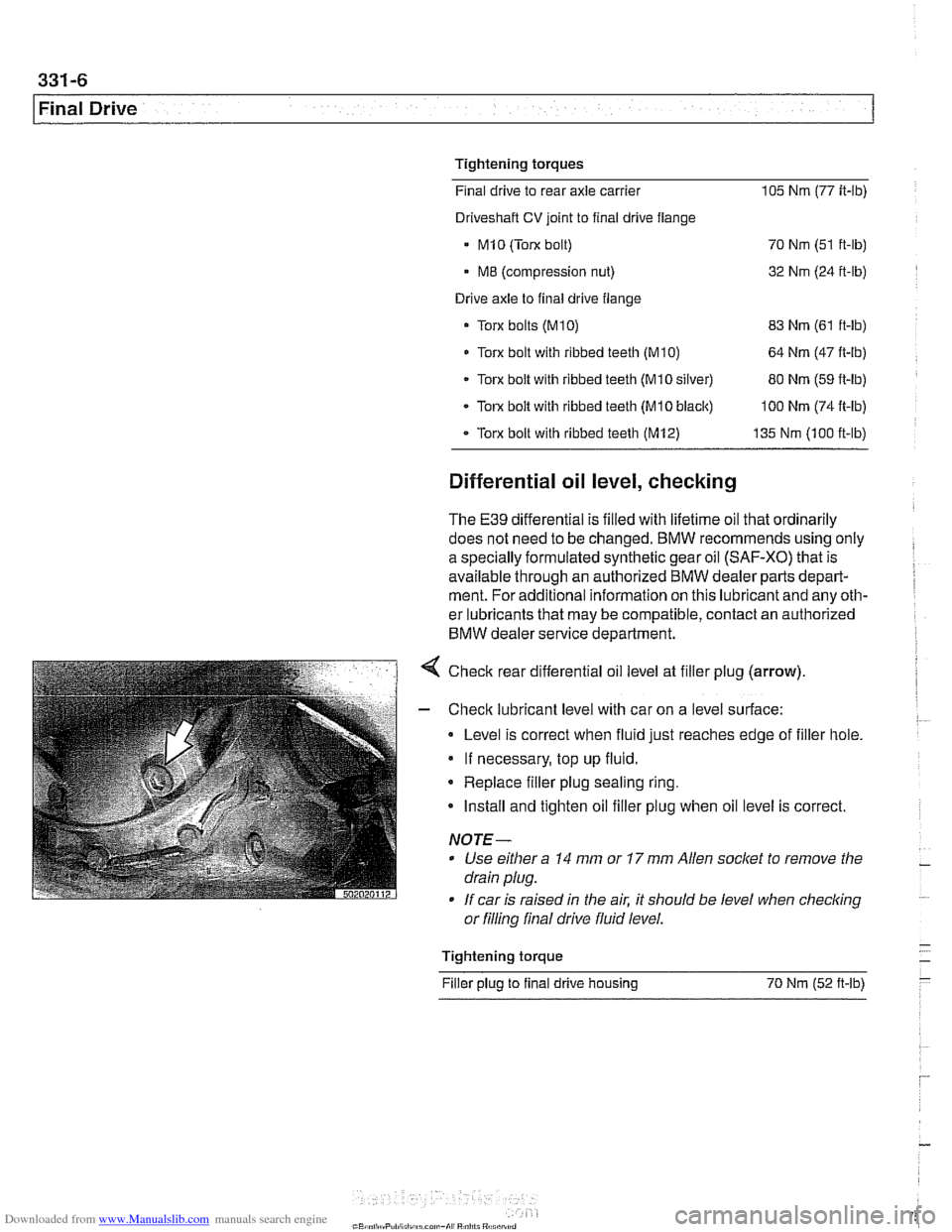
< Check rear differential oil level at filler plug (arrow).
- Check lubricant level with car on a level surface:
Level is correct when fluid just reaches edge of filler hole.
If necessary, top up fluid.
* Replace filler plug sealing ring.
Install and tighten oil filler plug when oil level is correct.
NOTE-
Use either a 14 mm or 17 mm Allen socket to remove the
drain plug.
If car is raised in the air. it should be level when
checkino " or filling final drive fluid level.
- Tightening torque -
Filler plug to final drive housing 70 Nm (52
ft-lb) -
Page 768 of 1002
Downloaded from www.Manualslib.com manuals search engine
340-6
1 Brakes
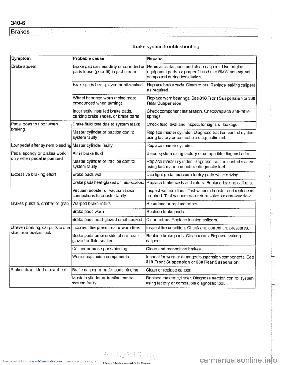
Brake system troubleshooting
/symptom I Probable cause 1 Repairs
Brake squeal
Pedal goes to floor when
bralting
Low pedal after system bleeding
Pedal spongy or brakes work
only when pedal is pumped
Excessive braking effort
Brakes pulsate, chatter or grab
Uneven
bralting, car pulls to one
side, rear braltes
loclt
Brakes drag, bind or overheat Brake
pad carriers dirty or corroded or
pads loose (poor fit) in pad carrier
Braite pads heat-glazed or oil-soaked
Wheel bearings worn (noise most
pronounced when turning)
Incorrectly Installed brake pads,
parking bralte shoes, or bralte parts
Brake fluid loss due to system leaks
Master cylinder or traction control
system faulty
Master cylinder faulty
Air in braite fluid
Master cylinder or traction control
system faulty
Brake pads wet
Brake pads
heat-glazedorfluid-soalted
Vacuum booster or vacuum hose
connections to booster faulty
--- Warped brake rotors
Brake pads worn
Brake pads heat-glazed or oil-soaked Remove
brake pads and clean calipers. Use original
equipment pads for proper fit and use BMW anti-squeal
compound during installation,
Replace brake pads. Ciean rotors. Replace leaking caliper:
as required.
Replace worn bearings. See 310 Front Suspension
or33C
Rear Suspension.
Check component installation. Checldreplace anti-rattle
springs.
Checlt fluid level and inspect for signs of leakage.
Replace master cylinder. Diagnose traction control system
using factory or compatible diagnostic tool.
Replace master cylinder.
Bleed system using factory or compatible diagnostic tool.
Replace master cylinder. Diagnose traction control system
using factory or compatible diagnostic tool.
Use light pedal pressure to dry pads while driving.
Replace
bralte pads and rotors. Replace leaking calipers.
lnspect vacuum lines. Test vacuum booster and replace as
required. Test vacuum non-return valve for one-way flow.
Resurface or replace rotors.
Replace brake pads.
Clean rotors. Replace leaiting calipers.
Incorrect tire pressures or worn tires
Brake pads on one side of car heat-
glazed or fluid-soaked
Caliper or brake pads binding
Worn suspension components
Brake caliper or brake pads binding
Master cylinder or traction control
system faulty lnspect
tire condition. Checlt and correct tire pressures.
Replace brake pads. Clean rotors. Replace leaking
calipers.
Clean and recondition brakes.
Inspect for worn or damaged suspension components. See
310 Front Suspension or 330 Rear Suspension.
Ciean or replace caliper.
Replace master cylinder. Diagnose traction control system
using faclory or compatible diagnostic tool.
Page 777 of 1002
Downloaded from www.Manualslib.com manuals search engine
340-1 5
Brakes
- Remainder of installation is reverse of removal.
- Clean brake caliper mounting bolts (7 mm Allen). Replace
ones which are not in perfect condition. Do not grease.
Top up brake fluid to MAX marking.
- Before driving car, pump bralte pedal several times so that
brake pads contact brake rotors.
Check that brake fluid level is correct. Top up if necessary.
Hold ignition key for at least
30 seconds in accessory po-
sition without starting engine. This clears any fault codes in
memory and turns off brake pad warning light.
Tightening torques Brake caliper to pad carrier
(7 mm Allen)
Front caliper
30 Nm (22 It-lb)
- Rear caliper 28 Nm (21 It-lb)
Road wheel to hub
120i 10 Nm (89i7 ft-lb)
Brake rotors, removing and installing
- Raise car and remove wheels
WARNING-
Male sure that the car is firmly supported on jack stands de-
signed for the purpose. Place jack stands beneath structural
chassis points. Do not place jack stands under suspension
parts.
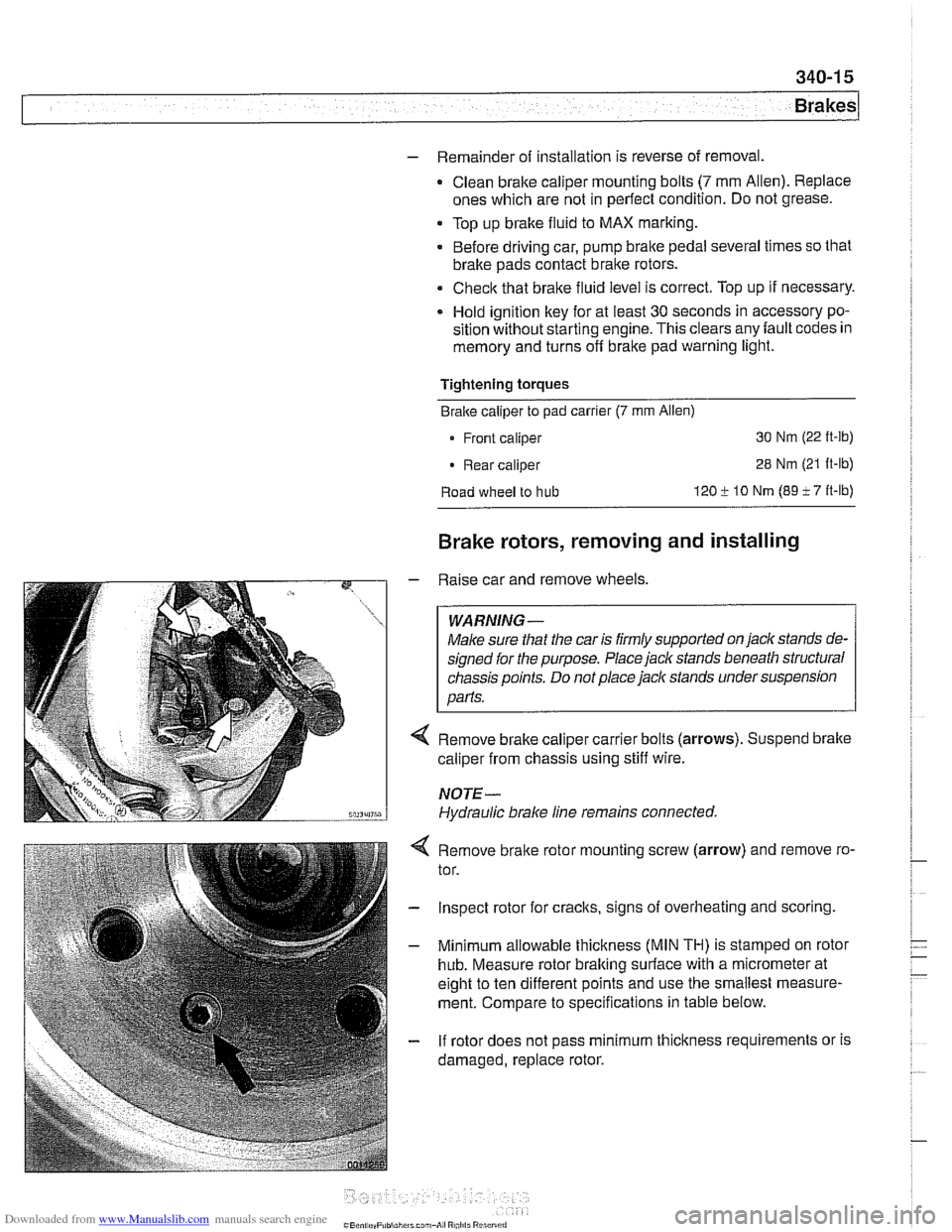
Remove brake caliper carrier bolts (arrows). Suspend brake
caliper from chassis using stiff wire.
NOTE-
Hydraulic brake line remains connected.
4 Remove bralte rotor mounting screw (arrow) and remove ro-
tor.
- Inspect rotor for cracks, signs of overheating and scoring.
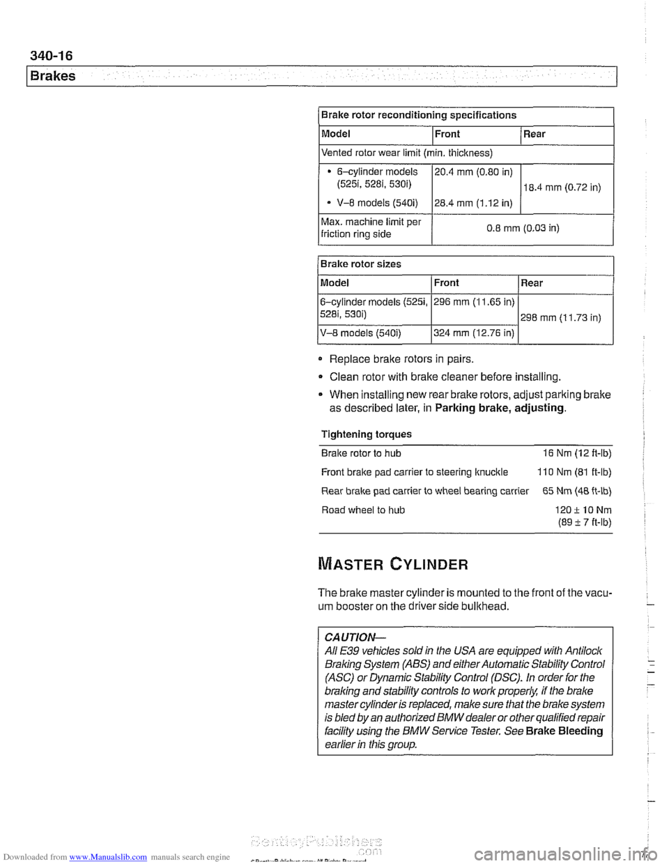
- Minimum allowable thickness (MIN TH) is stamped on rotor
hub. Measure rotor braking surface with a micrometer at
eight to ten different points and use the smallest measure-
ment. Compare to specifications in table below.
- If rotor does not pass minimum thickness requirements or is
damaged, replace rotor.
Page 778 of 1002
Downloaded from www.Manualslib.com manuals search engine
1 Brakes
Max. machine limit per
friction ring side 0.8 mm (0.03
in) I
Brake rotor reconditioning specifications
Model
Replace
braite rotors in pairs
Bralre rotor sizes
Clean rotor with brake cleaner before installing.
Front
Model
6-cylinder
models (5251,
5281, 530i)
V-8 models (540i)
* When installing new rear brake rotors, adjust pariting brake
as described later, in Parking brake, adjusting. Rear
Vented rotor wear limit (min. thickness)
Tightening torques
Braite rotor to hub 16 Nm (12 ft-lb)
6-cylinder models
(525i, 5281, 530i)
- V-8 models (540i)
Front
296 mm (1 1.65 in)
324 mm (12.76 in)
Front bralte pad
carrler to steering ltnucitle 110 Nm (81 ft-lb)
Rear
298 mm (1 1.73 in)
Rear
brake pad carrier to wheel bearing carrier 65 Nm (48 ft-lb)
20.4
mm (0.80 in)
28.4 mm (1.12 in)
Road wheel to hub
120ilONm
(89 -t 7 it-lb)
18.4 mm (0.72 in)
The brake master cylinder is mounted to the front of the vacu-
um booster on the driverside bullthead.
-
CAUTION-
All E39 vehicles soldin the USA are equipped with Antilock
Braling System (ABS) and either Automatic Stability Control
(ASC) or Dynamic Stability Control (DSC).
In order for the
braling and stability controls to work properk if the brake
master cylinder is replaced, make sure that the brake system
is bled
by an authorized BMW dealer or other qualified repair
facility
using the BMW Service Tester. See Brake Bleeding
earlier
in this group.