ECO BMW 525i 1997 E39 Workshop Manual
[x] Cancel search | Manufacturer: BMW, Model Year: 1997, Model line: 525i, Model: BMW 525i 1997 E39Pages: 1002
Page 780 of 1002
Downloaded from www.Manualslib.com manuals search engine
.- -
Brakes
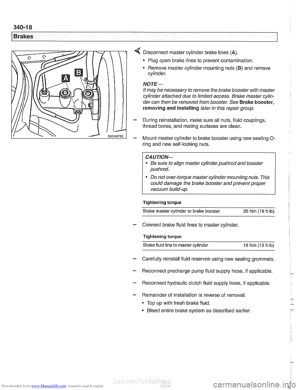
Disconnect master cylinder brake lines (A)
Plug open brake lines to prevent contamination.
Remove master cylinder mounting nuts
(6) and remove
cylinder.
NOTE-
It may be necessary to remove the brake booster with master
cylinder attached due to limited access.
Bralce master cylin-
dercan then be removed from booster. See Brake booster,
removing and installing later
in this repair group.
- During reinstallation, make sure all nuts, fluid couplings,
thread bores, and mating surfaces are clean.
- Mount master cylinder to bralte booster using new sealing O-
ring and new self-locking nuts.
CAUTIOI\C
* Be sure to align master cylinderpushrod and booster
pushrod.
* Do not over-torque master cylinder mounting nuts. This
could damage the brake booster and prevent proper
vacuum build-up.
Tightening torque Brake master cylinder to brake booster
26 Nm (19 ft-lb)
- Connect bralte fluid lines to master cylinder.
Tightening torque Brake fluid line to master cylinder
18 Nm (13 ft-lb)
- Carefully reinstall fluid reservoir using new sealing grommets.
- Reconnect precharge pump fluid supply hose, if applicable. -
- Reconnect hydraulic clutch fluid supply hose, if applicable.
- Remainder of installation is reverse of removal.
Top up with fresh brake fluid.
Bleed entire brake system as described earlier
Page 782 of 1002
Downloaded from www.Manualslib.com manuals search engine
Brakes
- Pump brake pedal a few times to reduce vacuum in brake
booster. This makes removal of
check valve easier.
- Remove or loosen hose clamp(s) at check valve.
- Disconnect hoses. Remove valve to test or replace.
NOTE-
If valve is pressed into grommet in vacuum booster, pry it out
carefully.
- Reinstall valve using new hose clamps
NOTE-
Install the valve so that the molded arrow is pointing toward
the intake manifold.
Brake booster, removing and installing
CAUTIO&
All E39 vehicles sold in the USA are equipped with Antiloclc
Braking System (ABS) and either Automatic Stability Control
(ASC) or Dynamic Stability Control (DSC). In order for the
bralchg and stability controls to work properk if brake fluid
lines are disconnected and reconnected,
male sure that the
brake system is bled by an authorized BMW dealer or other
qualified repair facility using the BMW Service Tester: See
Brake Bleeding earlier in this group.
- Disconnect negative (-) cable from battery.
I CAUTION- I
Prior to disconnecting the battery read the battery discon-
nection cautions given in
001 General Cautions and
I Warnings. I
- Remove bralte master cylinder as described earlier.
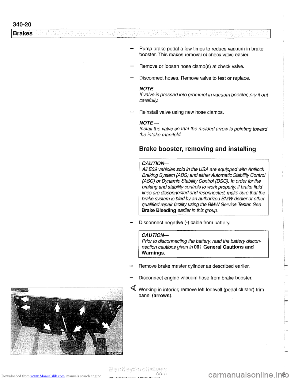
- Disconnect engine vacuum hose from bralte booster.
Page 784 of 1002
Downloaded from www.Manualslib.com manuals search engine
Brakes
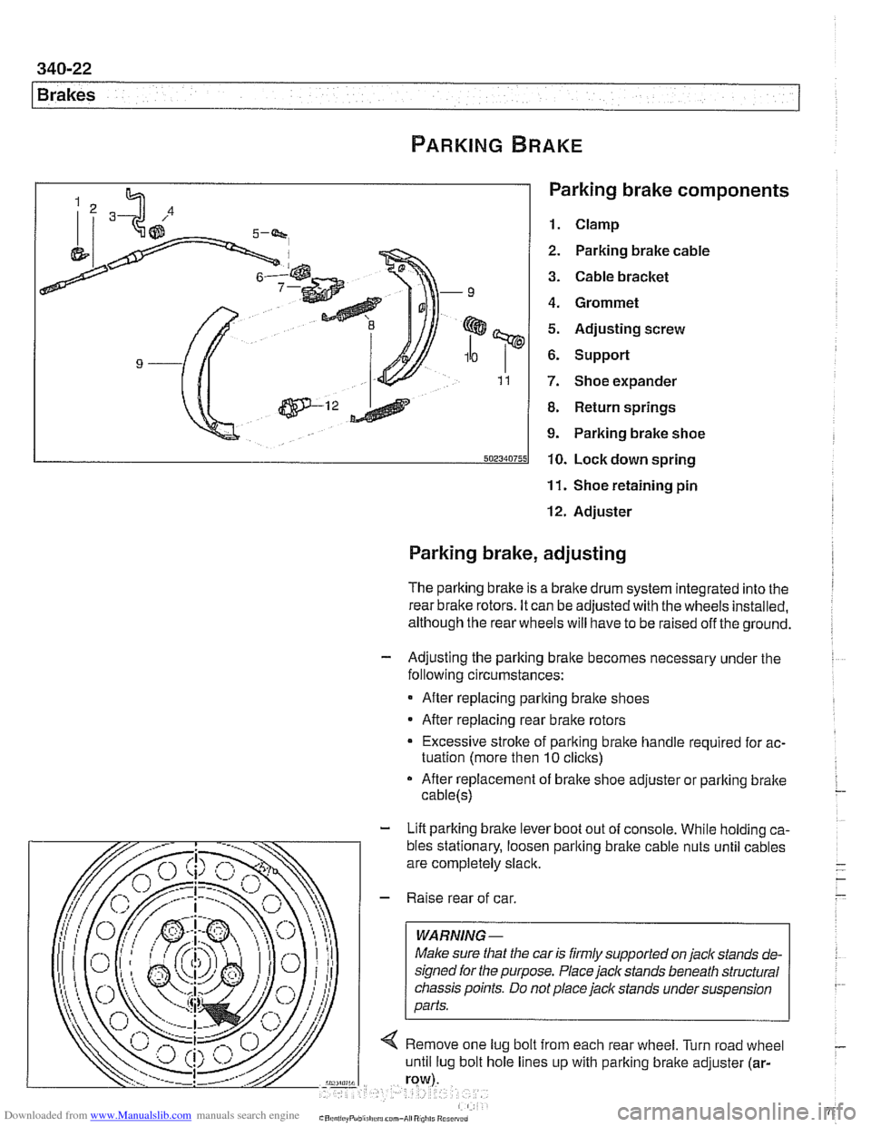
Parking brake components
1. Clamp
2. Parking brake cable
3. Cable bracket
4. Grommet
5. Adjusting screw
6. Support
7. Shoe expander
8. Return springs
9. Parking brake shoe
10. Lock down spring
11. Shoe retaining pin
12. Adjuster
Parking brake, adjusting
The parking brake is a brake drum system integrated into the I
rear brake rotors. It can be adjusted with the wheels installed,
although the rear wheels will have to be raised off the ground.
- Adjusting the parking bralte becomes necessary under the
following circumstances:
After replacing parking bralte shoes
After replacing rear brake rotors
Excessive stroke of parking brake handle required for ac-
tuation (more then
10 clicks)
After replacement of brake shoe adjuster or parking bralte
cable(s)
- Lift parking brake lever boot out of console. While holding ca-
Page 791 of 1002
Downloaded from www.Manualslib.com manuals search engine
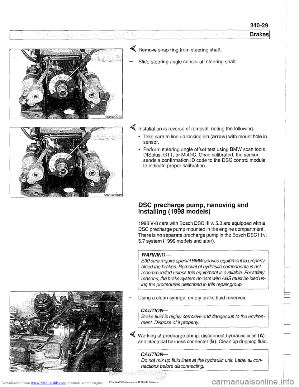
Remove snap ring from steering shaft.
- Slide steering angle sensor off steering shaft
< Installation is reverse of removal, noting the following.
Take care to line up loclting pin
(arrow) with mount hole in
sensor.
Perform steering angle offset test using BMW scan tools
DISplus, GT1, or MoDiC. Once calibrated, the sensor
sends a confirmation ID code to the DSC control module
to indicate proper calibration.
DSC precharge pump, removing and
installing
(1 998 models)
1998 V-8 cars with Bosch DSC Ill v. 5.3 are equipped with a
DSC precharge pump mounted in the engine compartment.
There is no separate precharge pump in the Bosch DSC
Ill v.
5.7 system (1999 models and later).
WARNING-
E39 cars require special BMWservice equipment to properly
bleed the brakes. Removal of hydraulic components is not
recommended unless this equipment is available. For safety
reasons, the
brake system on cars with ABS must be bled us-
ing the procedures described in this repair group.
- Using a clean syringe, empty brake fluid reservoir.
CAUTIOI\C
Brake fluid is highly corrosive and dangerous to the environ-
ment. Disoose of it
orooerlv.
Working at precharge pump, disconnect hydraulic lines (A)
and electrical harness connector (6). Clean up dripping fluid.
hydraulic unit. Label all
con-
Page 792 of 1002
Downloaded from www.Manualslib.com manuals search engine
1 Brakes
- Remove precharge pump mounting bracket fasteners and re-
move pump.
- Installation is reverse of removal, noting the following:
Be sure to replace rubber pump mounts if damaged
01
worn.
Bleed brakes as described earlier.
Tightening torque Brake line
to precharge pump 18 Nrn (13 ft-lb)
DSC pressure sensor (1 999 - 2002 models)
On 1999 and later DSC systems, the DSC pressure sensor is
screwed into the DSC hydraulic unit (right rear of engine com-
partment).
WARNING-
* €39 cars require special BMW service equipment to prop-
erly bleed the brakes. Removal of the
DSCpressure sensor
is not recommended unless this equipment is available. For
safety reasons, the brake system on cars with ABS must be
bled using the procedures described in this repair group.
Switch off ignition and remove
key to male sure brake
system cannot be activated.
- Disconnect electrical harness connector at switch.
- Use BMW special tool 34 5 160 to remove and install sensor.
Inspect threads and sealing surfaces for damage.
* Work quicltly to avoid excessive brake fluid leakage.
Tightening torque
Pressure sensor
to hydraulic 19 Nrn (14ft-lb)
unit
- Reconnect harness connector
- Bleed front brakes as described earlier.
- Press on brakes and check for leaks at sensor.
- Turn on ignition and firmly depress brake pedal. Check that
DSC warning light does not come on.
Page 793 of 1002
Downloaded from www.Manualslib.com manuals search engine
340-31
Brakes
ABS 1 traction electronic control module
(1 997 -1 998 models)
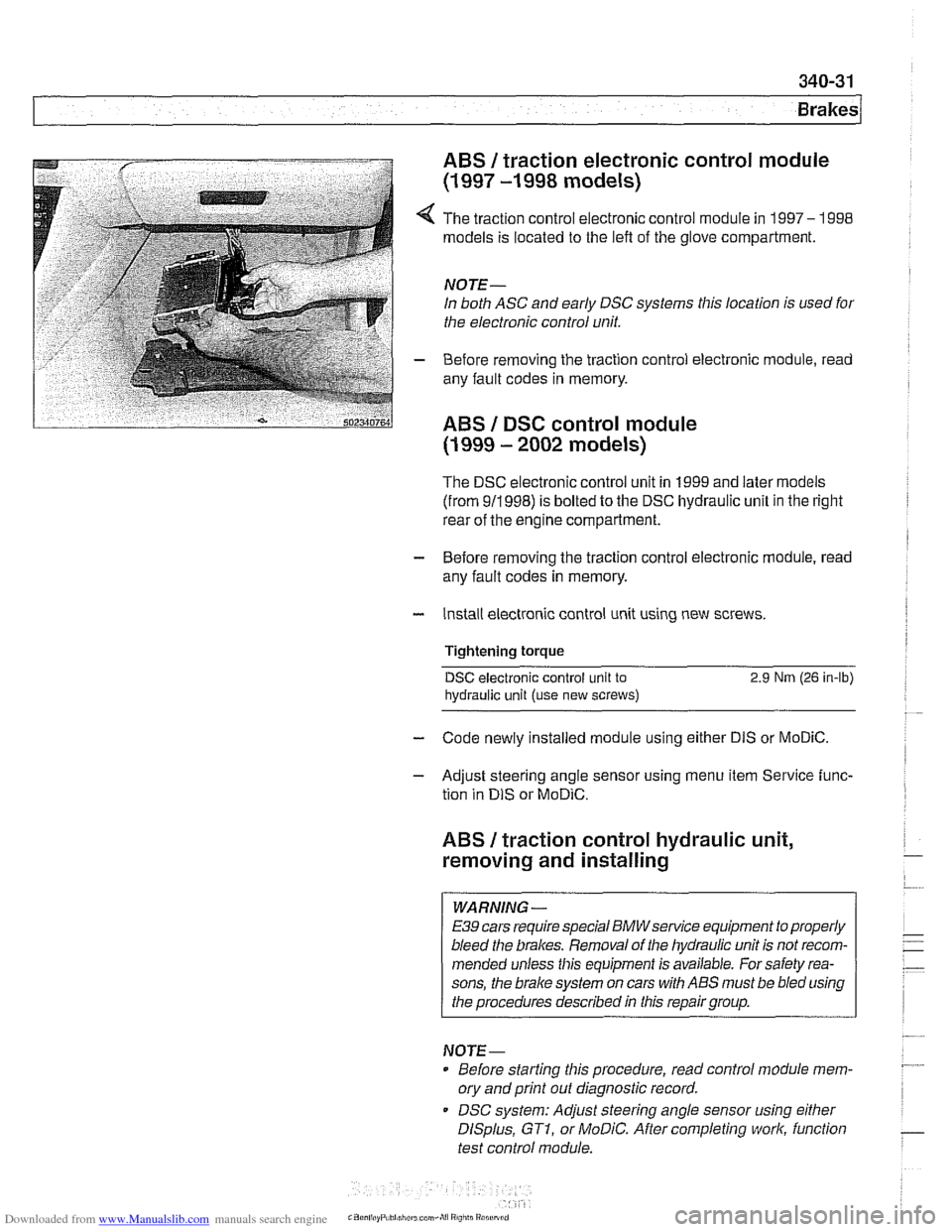
4 The traction control electronic control module in 1997- 1998
models is located to the left of the glove compartment.
NOTE-
In both ASC and early DSC systems this location is used for
the electronic control unit.
- Before removing the traction control electronic module, read
any fault codes in memory.
ABS I DSC control module
(1 999 - 2002 models)
The DSC electronic control unit in 1999 and later models
(from 911998) is bolted to the DSC hydraulic unit in the right
rear of the engine compartment.
- Before removing the traction control electronic module, read
any fault codes in memory.
- Install electronic control unit using new screws.
Tightening torque
DSC electronic control unit to 2.9 Nrn (26 in-lb)
hydraulic
unit (use new screws)
- Code newly installed module using either DIS or MoDiC.
- Adjust steering angle sensor using menu item Service func-
tion in
DIS or MoDiC.
ABS I traction control hydraulic unit,
removing and installing
WARNING -
E39 cars require special BMWsewice equipment to properly
bleed the brakes. Removal of the hydraulic unit is not recom-
mended unless this equipment is available. For safety rea-
sons, the
brake system on cars with ABS must be bled using
the procedures described in this repair group.
NOTE-
Before starting this procedure, read control module mem-
ory and print
out diagnostic record.
DSC system: Adjust steering angle sensor using
either
DISplus, GTI, or MoDiC. After completing work, function
test control module.
Page 797 of 1002
Downloaded from www.Manualslib.com manuals search engine
Body shell
Exterior and aerodynamics
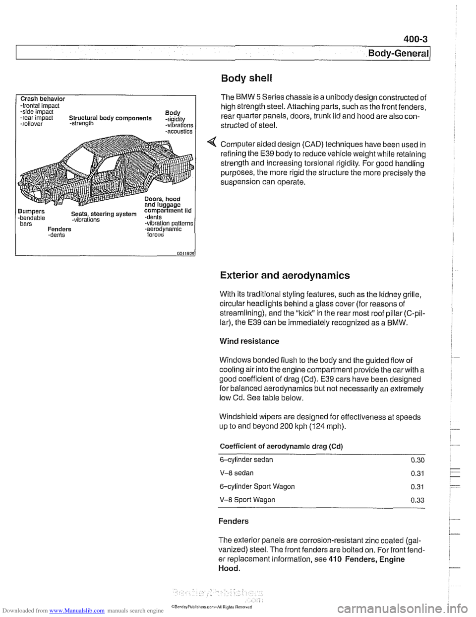
Crash behavlor -frontal impact
-side impact
Body
-rear impact Structural body components -rigidity
-rollover -strength -vibrations -acoustics
Bumpers compartment lid -bendable Seets,.steerlng system .dents -vibrations bars -vibration patterns
Fenders -aerodvnamic
With its traditional styling features, such as the ltidney grille.
circular headlights behind a glass cover (for reasons of
streamlining), and the
"kiclt" in the rear most roof pillar (C-pil-
lar), the E39 can be immediately recognized as a BMW.
The BMW 5 Series chassis is a unibody design constructed of
high strength steel. Attaching parts, such as the front fenders,
rear quarter panels, doors,
trunk lid and hood are also con-
structed of
steel.
Computer aided design (CAD) techniques have been used in
refining the
E39 body to reduce vehicle weight while retaining
strength and increasing torsional rigidity. For good handling
purposes, the more rigid the structure the more precisely the
suspension can operate.
Wind resistance
Windows bonded flush to the body and the guided flow of
cooling air into the engine compartment provide the
carwith a
good coefficient of drag (Cd).
E39 cars have been designed
for balanced aerodynamics but not necessarily an extremely
low Cd. See table below.
Windshield wipers are designed for effectiveness at speeds
up to and beyond 200
ltph (124 mph).
Coefficient of aerodynamic drag (Cd)
6-cylinder sedan 0.30
V-8 sedan 0.31
6-cylinder Sport Wagon 0.31
V-8 Sport Wagon 0.33
Fenders
The exterior panels are corrosion-resistant zinc coated (gal-
vanized) steel. The front fenders are bolted on. For front fend-
er replacement information, see
410 Fenders, Engine
Hood.
Page 840 of 1002
Downloaded from www.Manualslib.com manuals search engine
Trunk Lid, Tailgate I
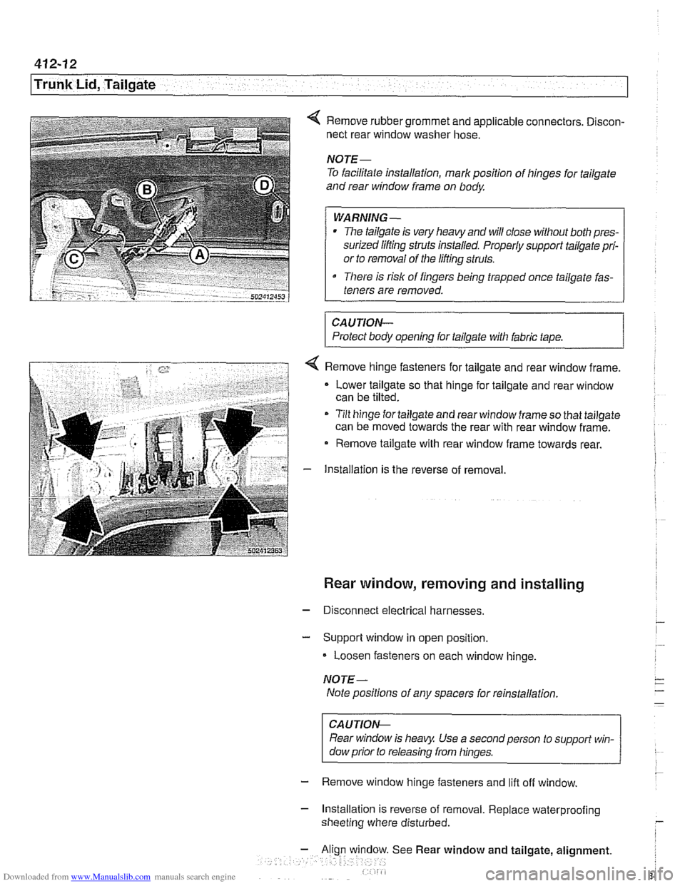
4 Remove rubber grommet and applicable connectors. Discon-
nect rear window washer hose.
NOTE-
To facilitate installation, mark position of hinges for tailgate
and rear window frame on body
WARNING-
The tailgate is very heavy and will close without both pres-
surized lifting struts installed. Properly support tailgate pri-
or to removal of the lifting struts.
There is risk of fingers being trapped once tailgate fas-
teners are removed.
CAUTION-
Protect body opening for tailgate with fabric tape.
4 Remove hinge fasteners for tailgate and rear window frame.
Lower tailgate so that hinge for tailgate and rear window
can be tilted.
- Tilt hinge for tailgate and rear window frame so that tailgate
can be moved towards the rear with rear window frame.
- Remove tailgate with rear window frame towards rear.
- Installation is the reverse of removal
Rear window, removing and installing
- Disconnect electrical harnesses.
- Support window in open position.
Loosen fasteners on each window hinge.
NOTE-
Note positions of any spacers for reinstallation
CAUTION-
Rear window is heavy Use a second person to support win-
dow prior to releasing from hinges.
- Remove window hinge fasteners and lift off window.
- Installation is reverse of removal. Replace waterprooiing
sheeting where disturbed.
See Rear window and tailgate, alignment.
Page 847 of 1002
Downloaded from www.Manualslib.com manuals search engine
Trunk Lid, Tailgate
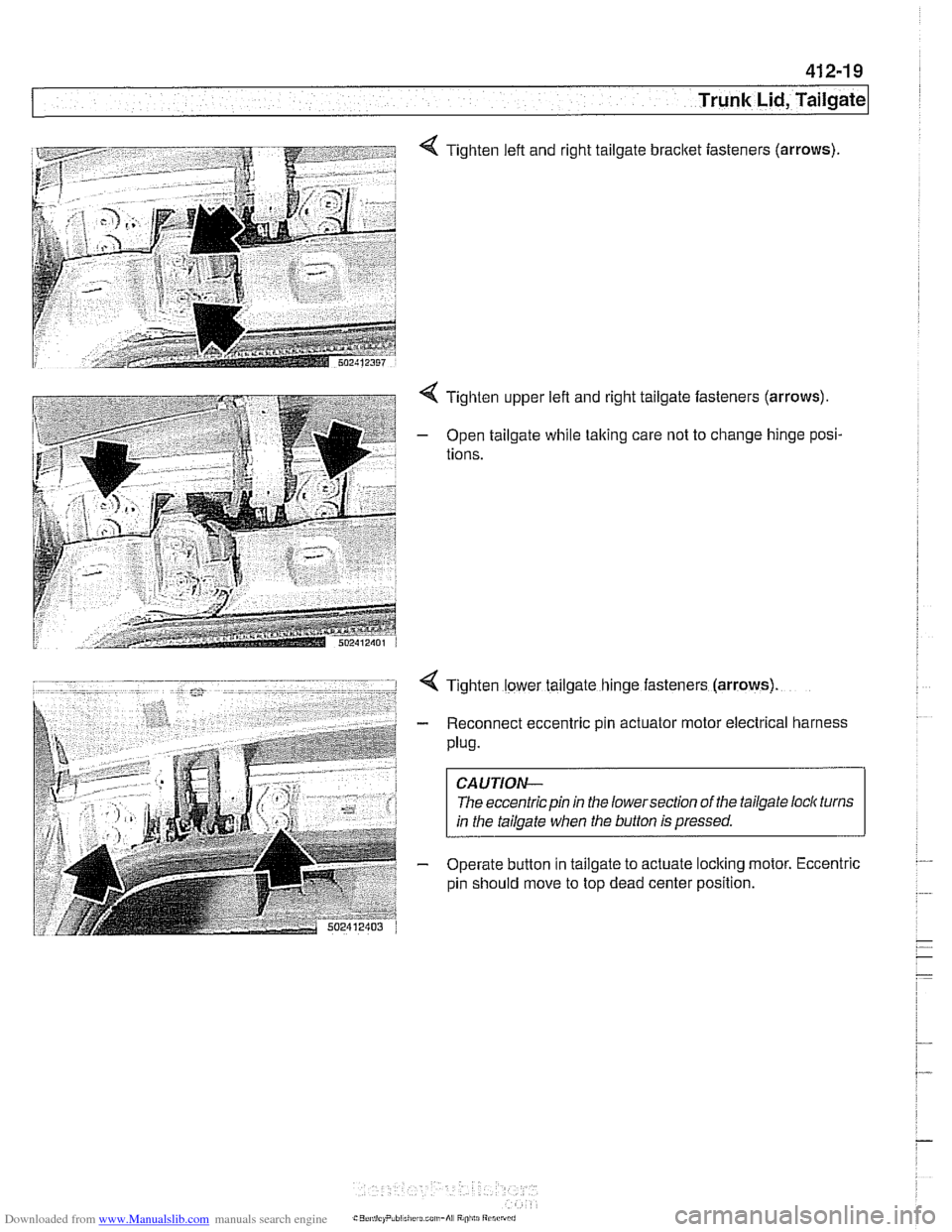
4 Tighten left and right tailgate bracket iasteners (arrows)
4 Tighten upper left and right tailgate fasteners (arrows).
- Open tailgate while taking care not to change hinge posi-
tions.
4 Tighten lower tailgate hinge fasteners (arrows)
- Reconnect eccentric pin actuator motor electrical harness
Plug.
CAUTION-
The eccentric pin in the lowersection of the tailgate loclc turns
in the tailgate when the button is pressed.
- Operate button in tailgate to actuate loclting motor. Eccentric
pin should move to top dead center position.
Page 858 of 1002
Downloaded from www.Manualslib.com manuals search engine
51 0-8
I Exterior Trim, Bumpers
- Installation is reverse of removal, noting the following:
Carefully slide bumper side panels over mounting brackets
on fenders.
Make sure gap between body and bumper is set to speci-
fications. Adjust height as necessary. See Front bumper
height, adjusting.
If equipped with headlight washers or
park distance control
reconnect hoses and harness.
Tightening torque Bumper to impact absorber
(M10) 41 Nm (30 ft-lb)
Front bumper impact absorber, replacing
To access front bumper mounting bracket and impact absorb-
er mounting hardware remove front bumper cover. See Front
bumper, removing and installing.
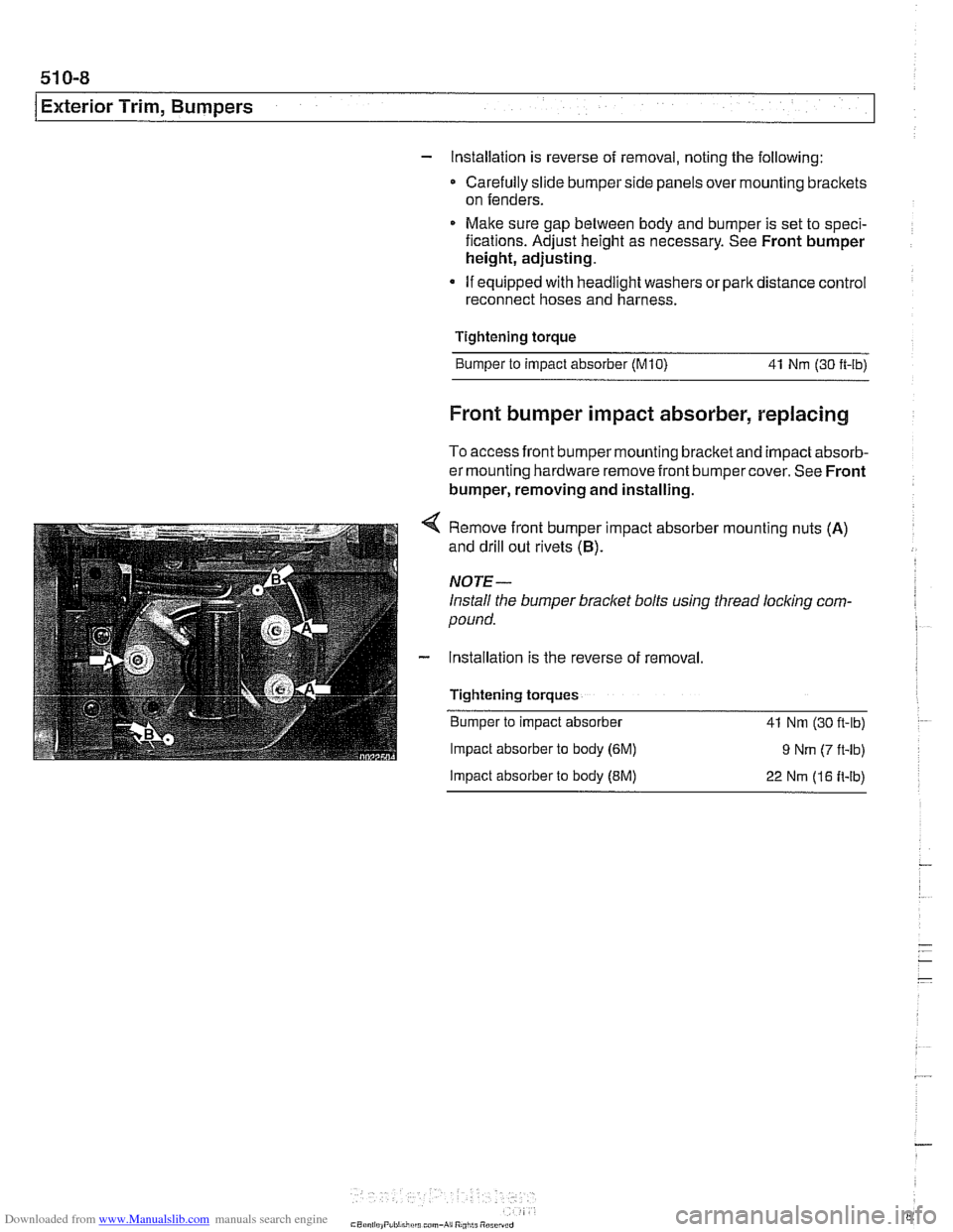
4 Remove front bumper impact absorber mounting nuts (A)
and drill out rivets (B).
NOTE-
Install the bumper bracket bolts using thread locking com-
pound.
- Installation is the reverse of removal.
Tightening torques Bumper to impact absorber
41 Nm (30 fl-lb)
Impact absorber to body (6M) 9 Nm (7 ft-lb)
Impact absorber to body (EM) 22 Nm (16 It-lb)