sensor BMW 525i 2000 E39 Workshop Manual
[x] Cancel search | Manufacturer: BMW, Model Year: 2000, Model line: 525i, Model: BMW 525i 2000 E39Pages: 1002
Page 535 of 1002
Downloaded from www.Manualslib.com manuals search engine
Exhaust systeml
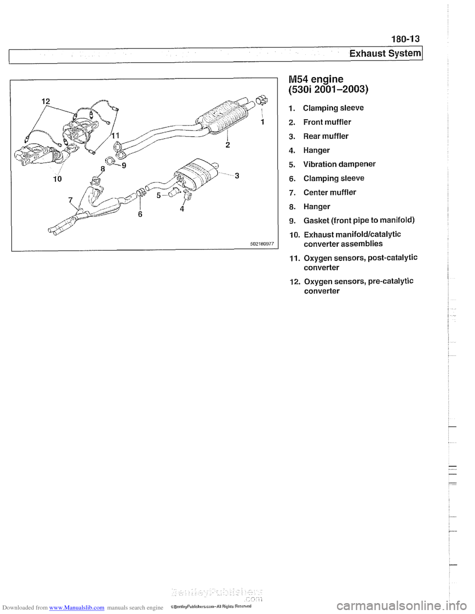
M54 engine
(5301 2001-2003)
Clamping sleeve
Front muffler Rear muffler
Hanger
Vibration dampener
Clamping sleeve
Center muffler
Hanger
Gasket (front pipe to manifold)
10. Exhaust
manifold/catalytic
converter assemblies
11. Oxygen sensors, post-catalytic converter
12. Oxygen sensors, pre-catalytic converter
Page 536 of 1002
Downloaded from www.Manualslib.com manuals search engine
I Exhaust System
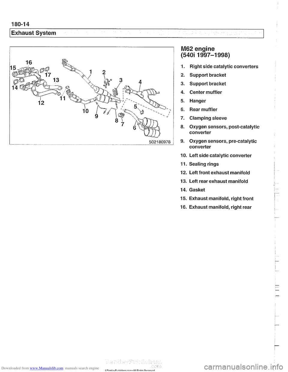
M62 engine
(540i 1997-1 998)
1. Right side catalytic converters
2. Support bracket
3. Support bracket
4. Center muffler
5. Hanger
6. Rear muffler
7. Clamping sleeve
8. Oxygen sensors, post-catalytic
converter
9. Oxygen sensors, pre-catalytic
converter
10. Left side catalytic converter
11. Sealing rings
12. Left front exhaust manifold
13. Left rear exhaust manifold
14. Gasket
15. Exhaust manifold, right front
16. Exhaust manifold, right rear
Page 537 of 1002
Downloaded from www.Manualslib.com manuals search engine
Exhaust systeml
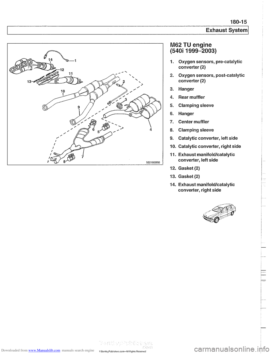
M62 TU engine
(540i 1999-2003)
1. Oxygen sensors, pre-catalytic
converter
(2)
2.
Oxygen sensors, post-catalytic
converter
(2)
3.
Hanger
4. Rear muffler
5. Clamping sleeve
6. Hanger
7. Center muffler
8. Clamping sleeve
9. Catalytic converter, left side
10. Catalytic converter, right side
11. Exhaust manifoldlcatalytic
converter,
left side
12. Gasket (2)
13.
Gasket (2)
14.
Exhaust manifoldlcatalytic
converter, right side
Page 556 of 1002
Downloaded from www.Manualslib.com manuals search engine
210-1 4
1 Clutch
Dowel sleeve I
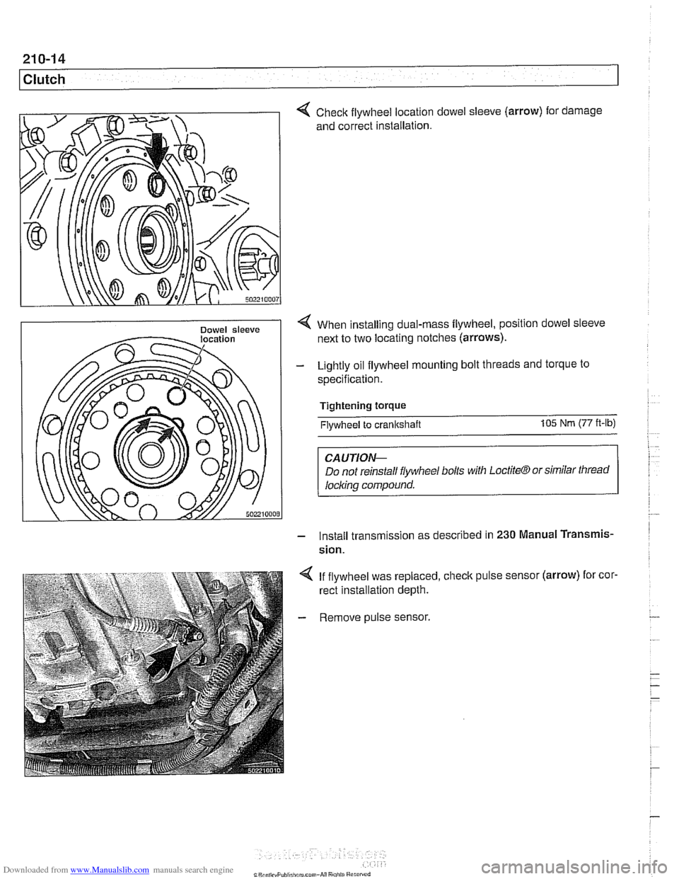
Check flywheel location
and correct installation. dowel sleeve
(arrow)
for . damage
< When installing dual-rnass flywheel, position dowel sleeve
next to two locating notches (arrows).
- Lightly oil flywheel mounting bolt threads and torque to
specification.
Tightening torque
Flywheel to crankshaft 105 Nm (77 ft-lb)
CAUTIOI\C
Do not reinstall flywheel bolls with LoctiteCTJ or similar thread
locl~ing compound.
- Install transm~ssion as descr~bed in 230 Manual Transmis-
sion.
4 If flywheel was replaced, check pulse sensor (arrow) for cor.
rect installation depth.
- Remove pulse sensor.
Page 557 of 1002
Downloaded from www.Manualslib.com manuals search engine
21 0-1 5
Clutch
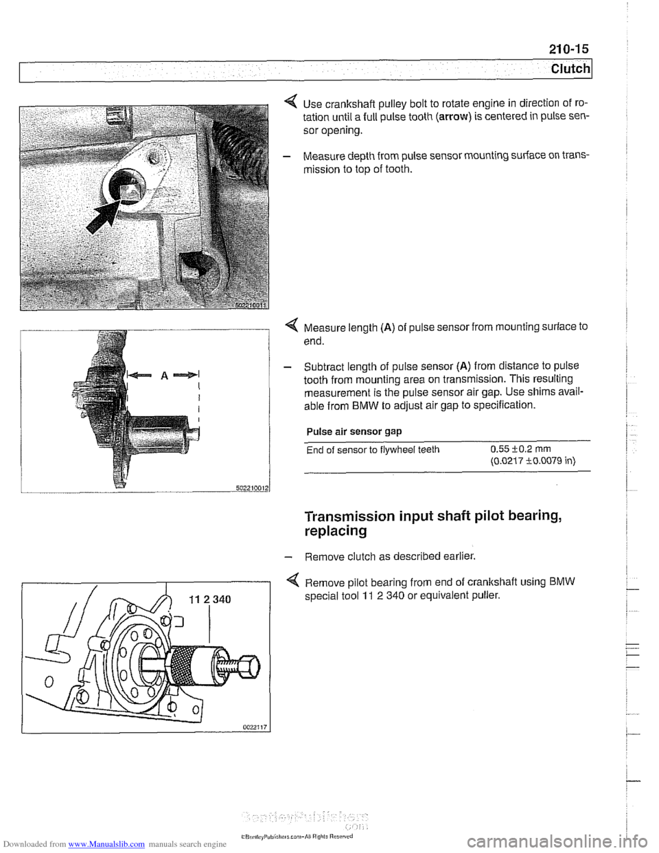
Use crankshaft pulley bolt to rotate engine in direction of ro-
tation until a full pulse tooth
(arrow) is centered in pulse sen-
sor opening.
Measure depth from pulse sensor mounting surface on trans-
mission to top of tooth.
Q Measure length (A) of pulse sensor from mounting surface to
end.
- Subtract length of pulse sensor (A) from distance to pulse
tooth from mounting area on transmission. This resulting
measurement is the pulse sensor air gap. Use shims avail-
able from
BMW to adjust air gap to specification.
Pulse air sensor gap
End of sensor to flywheel teeth 0.55 i-0.2 rnrn
(0.0217 i0.0079 in)
Transmission input shaft pilot bearing,
replacing
- Remove clutch as described earlier.
4 Remove pilot bearing from end of crankshaft using BMW
special tool 11 2 340 or equivalent puller.
Page 581 of 1002
Downloaded from www.Manualslib.com manuals search engine
--.
- - Manual Transmission
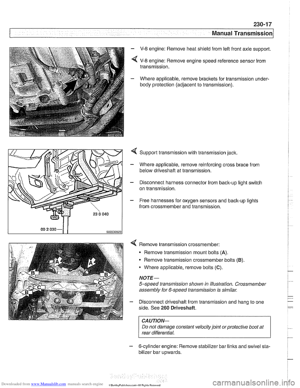
- V-8 engine: Remove heat shield from left front axle support.
< V-8 engine: Remove engine speed reference sensor from
transmission.
- Where applicable, remove brackets for transmission under-
body protection (adjacent to transmission).
4 Support transmission with transmission jack.
- Where applicable, remove reinforcing cross brace from
below driveshaft at transmission.
- Disconnect harness connector from back-up light switch
on transmission.
- Free harnesses for oxygen sensors and back-up lights
from crossmember and transmission.
Remove transmission crossmember: Remove transmission mount bolts
(A).
Remove transmission crossmember bolts (B)
Where applicable, remove bolts (C).
NOTE-
5-speed transmission shown in illustration. Crossmember
assembly for 6-speed transmission is similar.
Disconnect driveshaft from transmission and hang to one
side. See
260 Driveshaft.
I CAUTION- I
Do not damage constant velocity joint orprotective boot at
rear differential.
- 6-cylinder engine: Remove stabilizer bar links and swivel sta-
bilizer bar
u~wards.
Page 595 of 1002
Downloaded from www.Manualslib.com manuals search engine
Automatic ~ransmissionl
II I
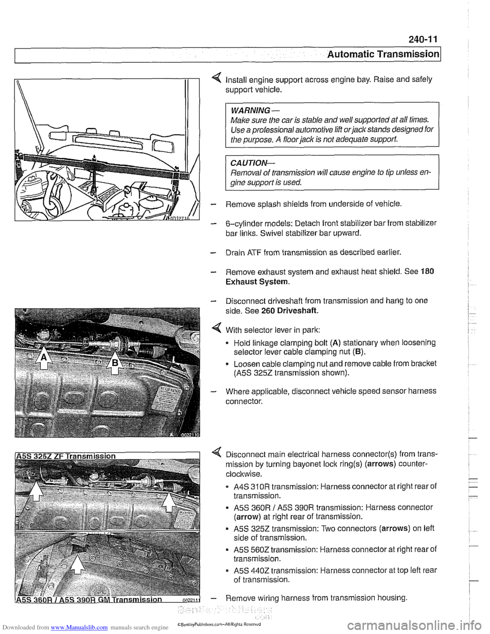
4 Install engine support across engine bay. Raise and safely
support vehicle.
Make sure the car is stable and
we1 supported at all times.
Use a professional automotive lift
orjaclc stands designed for
CAUTIOI\C
Removal of transmission will cause engine to tip unless en-
gine support is used.
- Remove splash shields from underside of vehicle.
- &cylinder models: Detach front stabilizer bar from stabilizer
bar
links. Swivel stabilizer bar upward.
- Drain ATF from transmission as described earlier.
- Remove exhaust system and exhaust heat shield. See 180
Exhaust System.
- Disconnect driveshaft from transmission and hang to one
side. See
260 Driveshaft.
4 With selector lever in park:
Hold
linkage clamping bolt (A) stationary when loosening
selector lever cable clamping nut
(6).
- Loosen cable clamping nut and remove cable from bracket
(ASS
3252 transmission shown).
- Where applicable, disconnect vehicle speed sensor harness
connector.
4 Disconnect main electrical harness connector(s) from trans-
mission by turning bayonet lock
ring(s) (arrows) counter-
clocltwise.
A4S
310R transmission: Harness connector at right rear of
transmission.
ASS
360R / ASS 390R transmission: Harness connector
(arrow) at right rear of transmission.
ASS 3252 transmission: Two connectors (arrows) on left
side of transmission.
ASS 5602 transmission: Harness connector at right rear of
transmission.
- ASS 4402 transmission: Harness connector at top left rear
of transmission.
- Remove wiring harness from transmission housing
Page 616 of 1002
Downloaded from www.Manualslib.com manuals search engine
260-1 0
/ Driveshaft
Driveshaft, installing
- Prepare CV joint for reinstallation:
Extend joint to limit.
Clean off old grease and fill with fresh grease
Install new seal.
- Bend driveshaft slightly at center universal joint to install
CAUTION-
Do not allow CVjoint seal to become displaced.
- Align matchmarlts on driveshaft to matchmarks on final drive
and transmission flanges.
- Fit constant velocity joint to final drive input flange. Alternate-
ly tighten two opposite nuts to draw constant velocity joint
evenly into the final drive input flange. Once seated, tighten
down remaining nuts.
I CAUTION-
I Do not reuse self-locking nuts. These nuts are designed to be /
I used onlv once. 1
- Insert bolts in front of driveshafl to transmission output
flange. Counterhold each bolt while tightening nut.
CAUTION-
. Do not reuse self-locking nuts. These nuts are designed to
be used only once.
Avoid stressing the flex-disc when torquing the bolts.
Do this by counterholding the bolts and turning the nuts
on the flange side.
- Position center support bearing and install mounting nuts.
Use new self-locking nuts.
- Install heat shields.
- Install rear transmission support crossmember.
- Install exhaust system. See 180 Exhaust System.
Reconnect oxygen sensor wiring harnesses and reattach
wiring harness retainers to rear transmission support
crossrnernber.
Page 630 of 1002
Downloaded from www.Manualslib.com manuals search engine
300-1 0
/Suspension, Steering and Brakes - General
The steering system features variable power assist provided
by an engine-driven hydraulic pump.
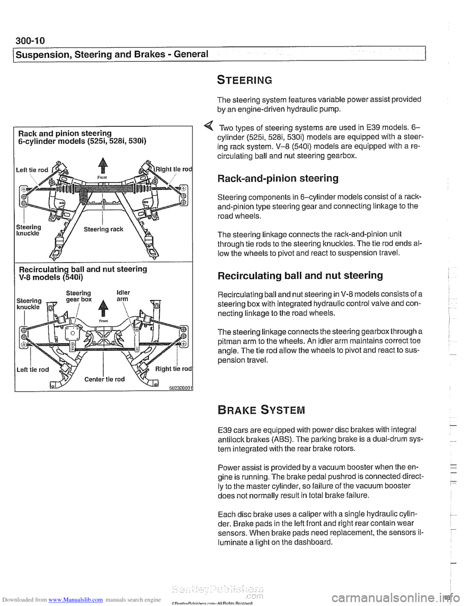
Rack and pinion steering
6-cylinder models
(525i, 5281, 5300
Two types of steering systems are used in E39 models. 6-
cylinder (525i, 5281, 530i) models are equipped with a steer-
ing rack system. V-8
(540i) models are equipped with a re-
circulating ball and nut steering gearbox.
Rack-and-pinion steering
Steering components in 6-cylinder models consist of a rack-
and-pinion type steering gear and connecting linltage to the
road wheels.
The steering linkage connects the rack-and-pinion unit
through tie rods to the steering knucltles. The tie rod ends al-
low the wheels to pivot and react to suspension travel.
Recirculating ball and nut steering
V-8 models
(540i)
I
Recirculating ball and nut steering
Recirculating ball and nut steering in V-8 models consists of a
steering box with integrated hydraulic control valve and con-
necting linkage to the road wheels.
Thesteering linkageconnects the steering gearbox through a
pitman arm to the wheels. An idler arm maintains correct toe
angle. The tie rod allow the wheels to pivot and react to sus-
pension travel.
E39 cars are equipped with power disc brakes with integral
antilock brakes (ABS). The parking bralte is a dual-drum sys-
tem integrated with the rear brake rotors.
Power assist is provided by a vacuum booster when the en-
gine is running. The brake pedal
pushrod is connected direct-
ly to the master cylinder, so failure of the vacuum booster
does not normally result in total
bralte failure.
Each disc bralte uses a caliper with a single hydraulic cylin-
der. Brake pads in the left front and right rear contain wear
sensors. When brake pads need replacement, the sensors il-
luminate a light on the dashboard.
Page 632 of 1002
Downloaded from www.Manualslib.com manuals search engine
300-1 2
I Sus~ension, Steerincl and Brakes - General
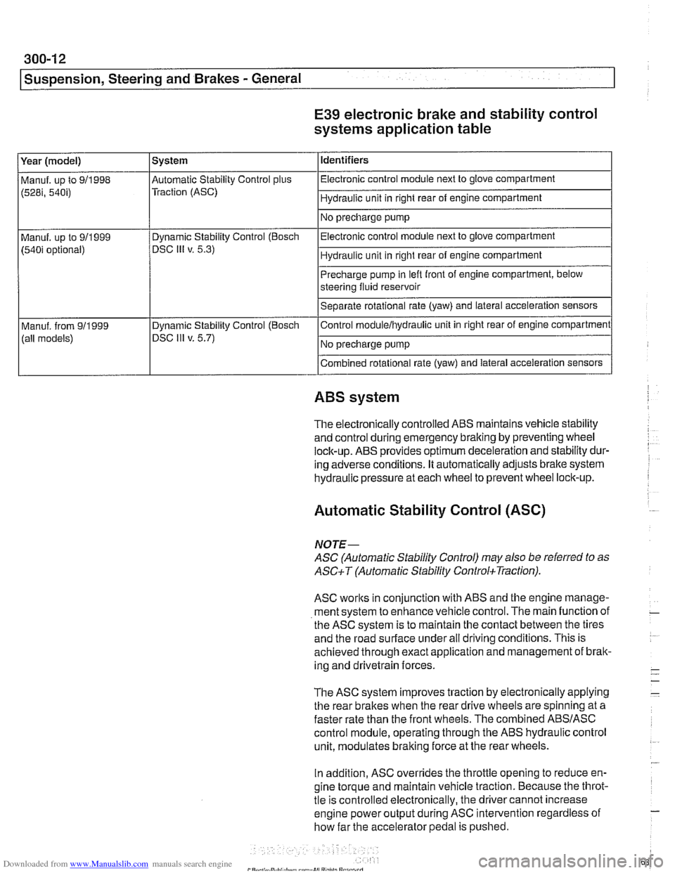
E39 electronic brake and stability control
systems application table
(528i, 54bi) Traction (ASC) I Hydraulic unit in right rear of engine compartment 1
Identifiers
Year (model)
I No precharge pump 1
Manuf. up to 911998 l~utomatic Stability Control plus I Electronic control module next to glove compartment
System
Precharge pump in
lefl front of engine compartment, below
steering fluid reservoir
Separate rotational rate (yaw) and lateral acceleration sensors
I I
Combined rotational rate (yaw) and lateral acceleration sensors
Electronic control
module next to glove compartment
Hydraulic unit in right rear of engine compartment
Manuf. up to 911999
(540i optional)
I I
ABS system
Dynamic Stability Control (Bosch
DSC
Ill v. 5.3)
The electronically controlled
ABS maintains vehicle stability
and control during emergency braking by preventing wheel
lock-up.
ABS provides optimum deceleration and stability dur-
ing adverse conditions. It automatically adjusts brake system
hydraulic pressure at each wheel to prevent wheel lock-up.
Control
moduleihydraulic unit
in right rear of engine compartment
No precharge pump
Manuf. from
911999
(all models)
Automatic Stability Control (ASC)
Dynamic Stability Control (Boscli
DSC Ill v. 5.7)
NOJE-
ASC (Automatic Stability Control) may also be referred to as
ASCiT (Automatic Stability ControkTraction).
ASC works in conjunction with ABS and the engine manage-
ment system to enhance vehicle control. The main function of
the
ASC system is to maintain the contact between the tires
and the road surface under all driving conditions. This is
achieved through exact application and management of brak-
ing and drivetrain forces.
The
ASC system improves traction by electronically applying
the rear brakes when the rear drive wheels are spinning at a
faster rate than the front wheels. The combined
ABSIASC
control module, operating through the ABS hydraulic control
unit, modulates braking force at the rear wheels.
In addition,
ASC overrides the throttle opening to reduce en-
gine torque and maintain vehicle traction. Because the throt-
tle is controlled electronically, the driver cannot increase
engine power output during
ASC intervention regardless of
how far the accelerator pedal is pushed.